
Abstract
Lunar rover development involves a large amount of validation works in realistic operational conditions, including its mechanical subsystem and on-board software. Real tests require equipped rover platform and a realistic terrain. It is very time consuming and high cost. To improve the development efficiency, a rover simulation environment called RSVE that affords real time capabilities with high fidelity has been developed. It uses fractional Brown motion (fBm) technique and statistical properties to generate lunar surface. Thus, various terrain models for simulation can be generated through changing several parameters. To simulate lunar rover evolving on natural and unstructured surface with high realism, the whole dynamics of the multi-body systems and complex interactions with soft ground is integrated in this environment. An example for path planning algorithm and controlling algorithm testing in this environment is tested. This simulation environment runs on PC or Silicon Graphics.
Introduction
Lunar rovers play an important role in the lunar surface exploration missions. These missions will require rovers to travel over challenging terrain to achieve ambitious scientific objectives. Future rovers are expected to traverse much longer distance over more challenging terrain with little ground intervention, achieve more complex tasks and have much longer mission life. Corresponding to the growing attention, there are an increasing number of researchers dealing with technological issues on exploration rovers. As a complicated system, development and validation of rover's mechanical subsystem and on-board software must be extensively tested. Take motion planning problem of robots for example. Over the years, numerous planning methods have been proposed, but many traditional motion planning methods can't be successfully applied in rough terrain environments, since they often assume perfect knowledge of the environment, ignore vehicle and terrain mechanics, and represent obstacle and free space in a binary format (Latombe 1991). Recently, researchers have begun addressing the rough terrain planning problem. Proposed search techniques include the A* and D* algorithms, genetic algorithms, and rapidly-exploring random trees (RRTs). These methods recognize the importance of model-based analysis to ensure path traversability. However, they generally utilize simplified terrain models and do not consider the uncertainty in the terrain data or robot path-following accuracy (K. Iagnemma 2004). So there is a strong need to develop a high fidelity environment for rover simulation, not only to support the testing of motion planning methods but also to support the early development, testing and maturation of other rover technologies for eventual mission use. Additionally, real tests require equipped rover platform and a realistic terrain. It is very time consuming and high cost.
A good simulation environment for rover need a good 3D terrain model, a whole rover dynamic model and an accurate contact dynamics model between them. As to 3D terrain model, it can be generally categorized as empirical and synthetic. Empirical terrain data is collected from manual measurement and optical surveying to high-precision radar and laser scanning techniques. Synthetic terrain is generated by some algorithms. They allow the user to specify general characteristics such as the range of rock sizes and distribution densities, along with other features such as craters. We use fractal technique and the statistical properties of the lunar surface to simulate the 3D terrain. Fbm is widely used in 3D terrain modeling (Mandelbrot 1977; Miller 1986; Musgrave 1989). But it is seldom used for lunar rover simulation.
As to modeling of mobile robots, many researchers have studied it. Kinematic and dynamic analysis of robots on flat terrain is a well-understood issue (Muir 1987; Sarkar 1994; Laumond 1998; Mutambara 2000). Kinematic analysis of six-wheeled robots with rocker-bogie suspensions have been presented in (Chottiner 1992; Linderman 1992; Hacot 1998; Tarokh 1999). Force analysis of mobile robots has also been performed. The mobile robot force analysis problem is similar to the force distribution problem in closed kinematic chains and walking machines, which has been studied in (Kumar and Gardner 1990; Kumar and Waldron 1990). Active coordination of forces in wheeled systems was proposed in (Kumar and Waldron 1989), and was later addressed in (Sreenivasan 1994; Sreenivasan and Nanua 1996). In general, there is a significant literature related to kinematic and dynamic modeling of mobile robots in both flat and uneven terrain. An important and often neglected aspect of robot system modeling is wheel-terrain interaction phenomena. Wheel-terrain interaction plays a critical role in rough terrain mobility, since traction characteristics are governed by terrain physical properties (Bekker 1956, 1969; Wong 1976). For example, a robot traveling through loose sand has very different mobility characteristics than one moving across firm clay. The classic approach to expressing the equations of motion was based on a Lagrangian formulation (J. J. Uicker 1967; M. E. Kahn 1971) of the problem. Algorithms developed using Lagrangian dynamics were O(n3), and had to be adapted for real-time control. The earliest known O(n) algorithm for forward dynamics was developed by Vereshchagin (1974). Later, Featherstone (1983) developed the ABA. The first version of this algorithm was applicable to manipulators with single degree-of-freedom joints, but the second included a general joint model and was faster (Featherstone 1987). Further gains have been made in efficiency over the years, with McMillan and Orin (1995) being representative of those that have reduced the computation (another 15% reduction).
As to rover simulator, Grand et al. (2002) developed a simulator tool which uses a semi-empirical model to introduce reaction forces between the multi-body dynamics simulator and the soil. In their research, various locomotion modes were simulated including peristaltic locomotion where leg-like degrees-of-freedom (DOF) enabled the suspension to be reconfigured to climb steep slopes. Yen et al. (1999) and Jain et al. (2003) describe the development of a virtual rover simulator called ROAMS which can be used for stand-alone simulations, closed-loop simulations with on-board software, or operator-in-the-loop simulations. Although ROAMS employs the Coulomb law for the contact dynamics, current work is focused on replacing this model with more accurate wheel-soil models.
From above analysis, VR techniques are seldom used in rover simulating, and terrain modeling are usually not considered. In this paper, VR techniques are used to construct a high fidelity physics based environment. We propose a simulation model of uneven lunar terrains based on fractional Brownian motions (fBm) and the real statistical properties. Using fBm model, various terrain models can be generated by changing only several parameters. The motion dynamics of a rover is discussed with the model that rovers' suspension mechanism is treated as an articulated multi-body system connected by free joint and differential joint, or a spring-damper mechanism. The motion of the rover is simulated using the driving force of the wheels as input. Wheel-terrain interaction mechanism is investigated and integrated to the dynamic model.
The rest of the paper is organized as follows. In section 2, overall architecture of the developed system is described. The method of generating the digital lunar surface is proposed in section 3. Multi-body simulating of lunar rover is discussed in section 4. Wheel-terrain interaction mechanism is introduced in section 5. A case study is included in section 6 to verify usefulness of the developed environment. Section 7 concludes, then discusses the future work.
System architecture
A key requirement on RSVE is that it provides a high-fidelity virtual environment for lunar rover simulation to support closed-loop testing beyond what is possible with just hardware rover test-beds. High-fidelity needs require RSVE to implement detailed physics based models of the rover including its kinematics and dynamics. As a surface vehicle, the lunar rover interacts with the environment primarily through the lunar surface. So, accurately modeling of lunar surface and the contact forces between it and the rover are the primary focus of environmental modeling in RSVE.
Figure 1 describes the system architecture of RSVE. The kinematics and dynamics module includes a multi-body kinematics and dynamics model of the lunar rover. The contact model uses DEM data as an input to compute the multi-body state of the rover. The result is transferred to the Virtual Environment to update the position and orientation of rover's visual model. DEM data is also an input to Path planning module for generating a navigation path. Motion control module get the path information then give steering/wheel motor torques command to Kinematics and Dynamics module. The following sections describe several key modules in additional detail.
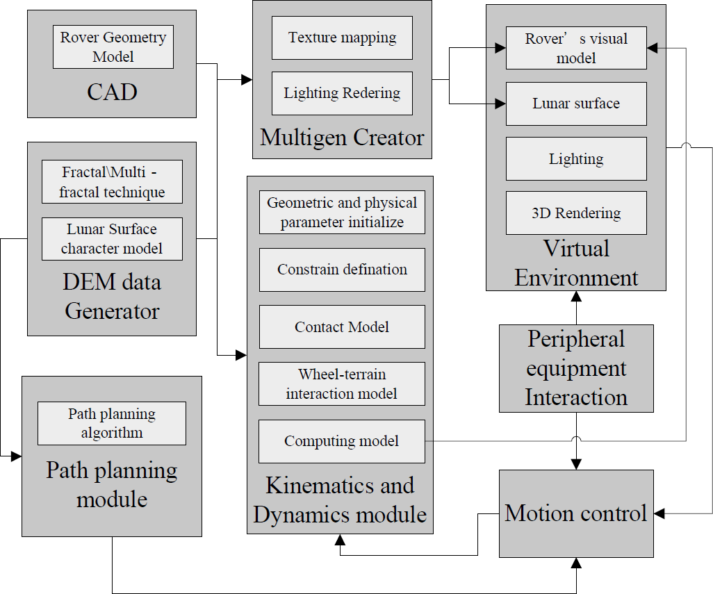
The RSVE system architecture
The terrain is represented by a digital elevation map (DEM). This terrain model is used to drive the wheel/soil interaction models, the path planning module (navigation and hazard avoidance models) as well as the 3D visualization engine. Since the roughness of terrains may vary from place to place even on the same planet, traversability should be checked on variety of terrains. Fractal theory shows that fractional Brownian motion (fBm) can mathematically represent complex shapes in nature, such as terrain, coastlines, clouds and mountains. In this paper, a realistic lunar surface simulation method is provided. It uses the fractal technology to form the base of lunar terrain and stones, adds lunar craters and stones to the base terrain according to the real statistical properties, then joint hill model around it, forming a realistic parameterized virtual lunar surface.
Kinematics and Dynamics module
Rover arm needs to position scientific instruments near objects of interest. Typical instrument arms have four or five degrees of freedom (DOF). RSVE includes an inverse kinematics engine for use with arms with different degrees of freedom. The Newton-Raphson solver is used to solve for the inverse kinematics. The x, y, z end position of the arm and an orientation constraint are the input.
The rover vehicle modeled in RSVE is the rocker-bogie of 6-wheeled rovers used for planetary surface exploration. Only front and rear wheels are steerable. Rover is treated as an articulated multi-body system connected by free joint, differential joint and spring-damper mechanism. In every simulation step, collision detection is called to get the result including geometry information and contact force as an input. An integrator is used to find the solution values at time t+h, given a time t, adjusting the state of all the rigid bodies for the new time value.
2.3 Path planning module
The Path planning module is responsible for accepting goal commands and generating a sequence of path information, which guides the rover to the goal while avoiding hazardous areas, according to the specific path-planning algorithm.
2.4 Motion control
The motion control module takes path information generated by the path planning algorithm and in turn generates steering and wheel motor commands needed to drive the rover following the planned path. Based on the knowledge that a rover can travel stably when the slip ratio is around 0, but it will be stuck when the slip ratio around 1 and the tangential force exerting to the soil exceeds the maximum share force, a traction control method to target the slip ratio at a small value and to limit the driving torque not to exceed the maximum share is also proposed.
3D Visualization
The 3D graphics visualization component of RSVE is built on OpenGL Performer. OpenGL Performer provides a programming interface (with ANSI C and C++ bindings) for creating real-time graphics applications and offers high-performance, multi-processed rendering in an easy-to-use 3D graphics toolkit. OpenGL Performer interfaces with the OpenGL graphics library; this library combined with the IRIX, Linux, or Micro-Soft Windows (Windows 2000, Windows NT, or Windows XP) operating system forms the foundation of a powerful suite of tools and features for creating real-time 3D graphics applications. RSVE uses OpenGL Performer to support rendering, such as viewpoint management, lighting and shading, camera control and scene-graph traversal and to manage peripheral equipment interaction.
Modeling of Lunar Surface
Virtual reality and computer graphics techniques for producing images are well developed. Constructing realistic virtual lunar surface is the base of our simulation environment. A realistic lunar surface simulation method is provided. It uses the fractal technology to form the lunar base terrain and stone upon the lunar surface, then adds lunar craters and stones to the terrain according to the real statistical data, then joint hill model around it, forming a realistic parameterized virtual lunar surface for lunar rover simulation.
One might argue that why we do not use the real terrain data. It's because that it is impossible to obtain whole terrain data in advance. Checking only on the partial terrain data might not be enough to ensure the robust traversability. On the other hand, the fBm model can generate a variety of terrains by introducing random numbers. To make the rover robust, we might also want to check the traversability on a terrain that is rougher than the real one. It is easy to make such a terrain model by changing the parameters.
Fractional Brownian motion (fBm)
Mandelbrot's fractional Brownian motion (fBm) is an effective mathematical method for modeling shapes found in nature. The one-dimensional fractional Brownian function, V
H
(t), which is a single valued function of one variable, t. ΔV
H
(Δt) = V
H
(t2) − V
H
(t1) follows a Gaussian distribution with variance
Simple crater models
Craters are caused by the high velocity impact of meteorites. There are mainly two basic types of crater that appear on the lunar surface: Simple Craters which are up to 10–20 km diameter which have a bowl shaped appearance and Complex Craters which are above 10–20 km diameter which have steep walls and relatively flat floors. According to the simulation needs that the area of the virtual lunar surface is not so wide, we only model the simple craters. Figure 2 shows a typical section plane of a simple crater.

The section plane of a simple crater
The depth of the crater, H, is given by

And the height of the crater rim above the surrounding terrain by

where D is the rim peak-to-peak crater diameter (Pike 1974).
In order to make meteorite impact craters appear realistic on a surface, the crater size density distribution must be correct as well as the individual crater models i.e. there must be many more small craters than there are large ones. The crater size density distribution varies across the lunar surface and has been measured in many areas (Melosh 1989). The general form of the crater size density distribution is given by

where N is the cumulative numbers distribution per unit area, D is the crater diameter, and b and c are constants. When b = 2, the constant c becomes dimensionless. Measurement of crater size density on the moon has provided a typical value for b of 1.8. Every time when we add a new simple crater to the base terrain, the relationship between the new crater and the existed craters should be judged and processed.
The stones generated in RSVE are also based on fBm. Different shape of stones can be generated by changing the Hausdorff parameter and the iterative primitives. Figure 3 shows typical stones generated in RSVE.

Typical stones generated in RSVE
All the stones are added to the based terrain according the following statistical information. Within 100 m2 of the lunar surface, the number of stones with height from 6cm to 25cm is about 100, with height from 25cm to 50cm is about 3 or 4, and stones with height more than 50cm is about 0.6. The ratio of the minimum size and maximum size of every stone is from 1:5 to 1:1.
Lunar rover is considered as articulated mechanisms with wheels in contact with the ground. Forward dynamics is a classical problem in robotics. Featherstone (1983; 1987) have presented the equations and algorithms for robot dynamics analysis. The most common approaches are known as Newton-Euler and Lagrange formulations. For our lunar rover model, 19 parameters are difined as following:
Position and orientation of rover body:

Angle of differential mechanism: α, and β1(i=1, 2),

Steering angle of rear and front wheels: Λ
i
(i = 1 ··· 4),

Rotational angle of the wheels : φ
i
(i = 1 ··· 6), set

All the external forces on the rover are expressed as following:
Wheel forces: f
wi
(i = 1 ··· 6), set

Force and moments on the base body: F 0 and N 0 ;
Torque on the steering joints : n
ri
(i = 1 ··· 4), set

Driving torque of the wheels : n
wi
(i = 1 ··· 6), set

Torque on the suspension joints: n
si
(i = 1 ··· 3), set

Thus, we can get the system's kinetic energy T. Steering motors control the steering angle, and the driving motor control the angular velocity. Hence we get 10 contraint equations, including 4 ideal contraint equations and 6 non-ideal contraint equations.


Thus, 4 generalized coordinates
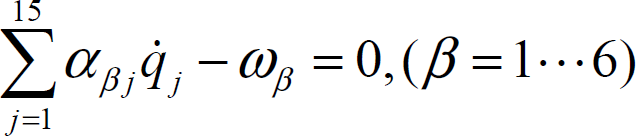
where q
j
represents some of the generalized coordinates, αβj are constants. According to the Routh Equations, we get:
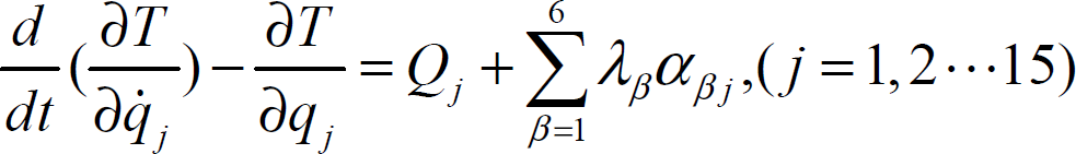
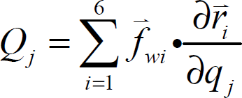
Where Λβ are Lagrange Multipliers, Q
j
are the generalized force, defined as following:
So we get the dynamical equations:
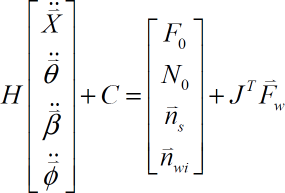
Where H is the matrix form given by the 1st terms in Routh equations, and C represents the effects for these terms of non-ideal constraints,
Wheel-terrain interaction plays a critical role in rough terrain mobility (Bekker 1969; Wong 1976). Numerous researchers have developed models of wheel-terrain interaction that rely on physical terrain parameters. According to the stiffness of both lunar rover wheels and the terrain, we assume that wheel is rigid and the terrain is soft. A free-body diagram of driven rigid wheel of radius r and width b traveling through deformable terrain is shown in figure 4. A vertical load W and horizontal drawbar pull force DP are applied to the wheel center has linear velocity V. The angle from vertical at which the wheel first makes contact with the terrain is denoted θ1. The angle from the vertical at which the wheel loses contact with the terrain is denoted θ2.
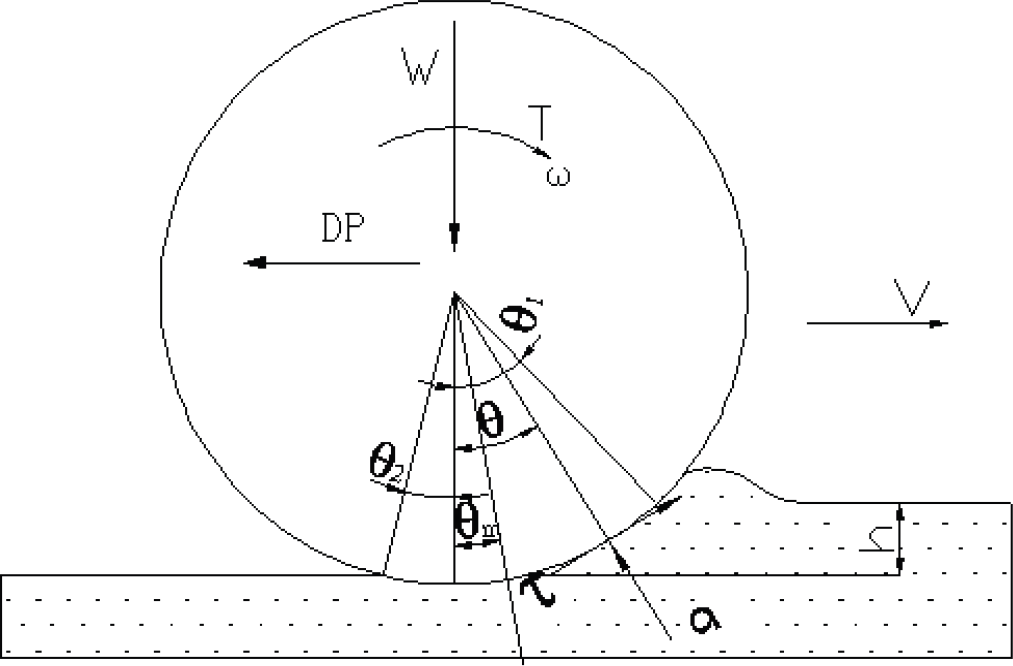
A rigid wheel on deformable terrain
For such a model, a formula is known to describe the relationship between the share stress τ(θ) and the normal stress σ(θ) of loose soil beneath the wheel (Wong 1976):

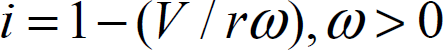
Where k is the shear deformation modulus, r is the wheel radius, and i is the wheel slip, defined as:
Also, another formula for the normal stress to relate the wheel's vertical sinkage h has been proposed (Bekker 1969):

where the geometrical relationship for h is:

In the above equations, c is cohesion stress of the soil, ϕ is internal friction angle of the soil, b is wheel width, n, k, k1 and k2 are constants
By integrating σ and τ over the entire contact area, from θ2 to θ1, we obtain the normal and tangential forces exerting on the wheel:

for the normal force that is balanced to the load W, and

for the tangential force that is called drawbar pull.
Our VR hardware environment is a PowerWall system including a SGI ONYX 3200 workstation, three BARCO projectors as well as some other peripheral equipment such as FOB, digital glove, stereo glass.
A kind of prototype of lunar rover designed by Shanghai Aerospace System Engineering is simulated in RSVE.
Lunar surface simulation
According to the method proposed in section 3, a terrain is generated as shown in figure 5. Figure 5-A is the grid model of the central part of the virtual lunar surface, with Hausdorff parameter H = 0.5 Fig 5-B shows the result after texture mapping. Figure 5-C shows a typical simple crater. Figure 5-D shows a complete model with deferent size and shape of stones distributed upon it and a hill model around it.

Virtual lunar surface
Figure 6 shows a simulation process of lunar rover autonomously traveling. Mouse clicking gives the target position and a flag will be placed on the clicked position as a marker. A path-planning algorithm will be called. Then a path will be generated according to the terrain information as well as the start position and the target position. The control module will control the rover to follow the path generated by the path- planning algorithm. Thus, different algorithms can be tested and evaluated in this immersive environment, though the path planning algorithm in RSVE now is simply advoiding the predefined big obstacles.
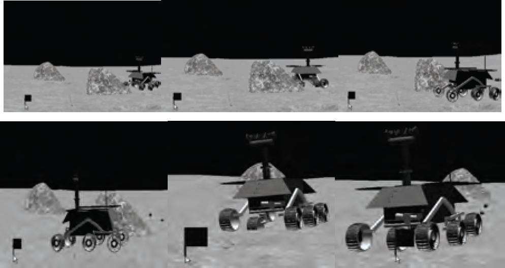
A simulation example of lunar rover
In this paper, virtual reality technique is used to generate a realistic virtual environment for lunar rover simulation called RSVE. Fractional Brown motion technique and the real statistical information are used to simulate the lunar surface. It has many advantages over alternative methods of simulating the unknown uneven terrain for lunar rover simulation. Kinetic and dynamic model of lunar rover and wheel-terrain interaction mechanics is investigated. A dynamics simulation model is developed considering the mechanics of wheel-terrain interaction, and the articulated body dynamics of lunar rover's suspension mechanism. A lunar rover prototype has been tested in this environment including its mechanical subsystem, motion control algorithm and a simple path planning algrithm, other path planning algorithm can be extended in this system easily. According the testing result, RSVE is an effective tool for lunar rover designing.
As future works, other components such as vision-based guidance algorithm, power subsystem model and simulation result post-processing module will be added to the system. The relative experiments will also be carried to validate the model proposed in this paper.
Footnotes
8.
The research work was performed at the VR Lab of Shanghai Jiao Tong Univ. CIM institute, under contract with the Aerospace System Engineering, Shanghai.