
Abstract
This paper provides algorithms to estimate absolute navigation information, e.g., absolute attitude and position, by using low power, weight and volume Microelectromechanical Systems-type (MEMS) sensors that are suitable for micro planetary rovers. Planetary rovers appear to be easily navigable robots due to their extreme slow speed and rotation but, unfortunately, the sensor suites available for terrestrial robots are not always available for planetary rover navigation. This makes them difficult to navigate in a completely unexplored, harsh and complex environment. Whereas the relative attitude and position can be tracked in a similar way as for ground robots, absolute navigation information, unlike in terrestrial applications, is difficult to obtain for a remote celestial body, such as Mars or the Moon. In this paper, an algorithm called the EASI algorithm (Estimation of Attitude using Sun sensor and Inclinometer) is presented to estimate the absolute attitude using a MEMS-type sun sensor and inclinometer, only. Moreover, the output of the EASI algorithm is fused with MEMS gyros to produce more accurate and reliable attitude estimates. An absolute position estimation algorithm has also been presented based on these on-board sensors. Experimental results demonstrate the viability of the proposed algorithms and the sensor suite for low-cost and low-weight micro planetary rovers.
1. Introduction
Planetary rovers are a special type of unmanned ground vehicles, characterized by their extremely slow speed and rotation. These rovers move in a stop-and-go fashion, so that they can scan their surroundings to find drivable paths and scientific targets in the targeted exploration area. For example, NASA's Mars rovers have an average speed of 1 cm/s when they move on hard and plane surfaces and even less quickly in normal motion. The rover is programmed to drive for approximately 10 seconds, then to stop, observe and understand the surrounding terrain for 20 seconds, then to move safely onward for another 10 seconds, and so on [1]. A typical motion scenario of a planetary rover includes stop-and-go, straight drives, arc turns and turn-in-place manoeuvres[2], as depicted in Figure 1.

Typical motion scenario of a planetary rover: stop-and-go, turn-in-place (TiP), straight and curved paths
Autonomous navigation or localization is a stringent requirement for operating any kind of manned/ unmanned vehicle in a target environment. A very simple method to achieve this is the process of dead reckoning. This method involves determining a platform's pose without using any external information except for what the platform senses using on-board sensors only. A simple example of dead reckoning navigation is using wheel encoders to sense the rotation and steering of the wheels of the vehicle and, hence, estimate the translational and rotational motion changes occurring in a given period. The other, more common, method is using an inertial measurement unit (IMU) to keep track of the pose of any vehicle in three-dimensional space. However, the dead reckoning process of navigation is prone to divergence over time, due to the inherent growth in errors produced by mathematical integration processes used to extract the useful navigation information, e.g., position, velocity, attitude etc., from wheel rotation or inertial sensors, only.
For terrestrial applications, there are many kinds of different and complementary navigation sensors available to guide a vehicle on the ground, in the air or underwater. However, planetary rovers do not use plenty of navigation sensors/systems on remote planets. For example, the global positioning system (GPS), a commonly available navigation system for many types of ground, air and sea-surface vehicles, is not applicable on the Moon or on Mars. A magnetic compass, commonly employed for producing heading estimations on Earth, cannot be used reliably on other planets. For example, the magnetic field on the lunar surface is too weak and irregular to be useful as a navigational aid. Similarly, gyro-compassing, which is a method of north-seeking by high-grade IMUs using the Earth's rotation, is not suitable on the Moon's surface due to the extremely slow rotation of the Moon around its own axis, as compared to the Earth's rotation. Digital maps are either not available at all or have too low resolution to provide accurate navigation information for the planetary rovers. Moreover, heading estimation is not possible using maps. All of this makes planetary rovers difficult to navigate in a completely unknown and complex environment. There is an urgent need to estimate accurate absolute attitudes and positions of the rover on remote planets.
Although relative navigation information (which is achieved through mathematical integration of the information provided by on-board sensors, e.g., dead reckoning) can be obtained in a similar way as for ground vehicles, the absolute (global) navigation information, e.g., absolute roll, pitch and, especially, heading is difficult to obtain on other planets' surfaces [3]. The reason for this has been described above. Other reasons to incorporate absolute-navigational information in the navigation framework of a rover is to bound the unbounded error growth of a dead-reckoning navigation system (especially the absolute heading), which is essential to reduce cross-track errors in positioning.
Planetary rover navigation had been an intensively researched area among the research community, well before the launch of the Mars Pathfinder mission by NASA in 1997. A Sun sensor was developed for planetary rovers' heading estimations in [4], but the algorithm was computationally too expensive to be used on real rovers. Further improvements to the design and usage are provided by [5]. A Charge-Coupled Device (CCD) camera-type Sun sensor, having a wide FOV modelled as a fish-eye lens that involves a complex calibration procedure with 21 parameters is used in [6]. In a CCD-type sensor, finding the Sun's centroid with image processing techniques induces errors at low elevations of the Sun and at local noon. The authors report that the maximum error due to low elevation and radial distortion is about 1° in a heading estimation. During a turn-in-place motion, they observed a maximum 3° error in heading. Although much error analysis has been provided, they have yet to mature their algorithm. An absolute heading estimation and relative position estimation algorithm is provided by [7]. Their work uses a Sun sensor, an Earth sensor and an inclinometer. It describes nicely the attitude estimation algorithm from multiple vector observations using the q-method, which is a nonlinear minimization problem. It also proposes the position propagation using wheel odometry and, in the same fashion, the propagation of the absolute position (longitude, latitude) as the rover moves over the lunar surface. They validate their propositions only through simulation results. A Position-Sensitive Device-type (PSD) Sun sensor, similar to the one used in this work, is used in [8,9]. The PSD-type Sun sensor uses less power and a simple algorithm with fewer atmospheric effects and good robustness in order to detect the Sun's position in a sensor frame. They provide an algorithm for absolute heading and absolute position estimation using the Sun sensor and an inclinometer, but the results are not good enough due to errors in the inclinometer. They also provide a heading verification method using GPS observation in outdoor field experimentation, where the magnetic compass is not good enough to use. They achieve absolute heading to within a few degrees and use a nonlinear minimization approach which requires much more time than ours, which is a one-shot heading estimation process and can be applied in real time with a 10Hz update rate. Until now, only high-grade IMUs have been used for space applications, but with the dawn of the MEMS technology, an effort is being made to develop very small IMUs with low cost, weight and power consumption requirements. For example, the European Space Agency (ESA) and the European Space Research and Technology Center (ESTECH) have developed and tested a MEMS IMU for space applications [10,11].
The solution to the above navigational problems on planetary surfaces is to fuse the low-cost and low-weight relative and global sensors available in a planetary environment to achieve the desired accuracy level, i.e., a 10% error in position per 100m and less than 2° in attitude [12], taking into account all possible motion scenarios, e.g., a long time spent stationary, moving on an arbitrary path and elevation and making a turn-in-place motion, as shown in Figure 1.
This paper focuses on the estimation of absolute navigation information, and further fuses information from gyros and absolute attitudes to improve the accuracy and robustness in the framework of an Extended Kalman Filter (EKF). The Sun sensor is used in combination with an inclinometer for absolute rover-heading estimations, and the inclinometer is used for absolute tilt (roll and pitch) angle estimations in all motion scenarios, i.e., when the rover stops for a long time, makes a turn-in-place motion or is moving continuously in the stop-and-go mode. An absolute position-estimation algorithm is also presented based on this work, but the results are quite coarse, using on-board MEMS-type sensors, in the range of kilometres [8].
Further organization of this paper is as follows. In Section 2, a description is given of the reference frames used in this work. Section 3 presents the attitude initialization and propagation procedures, and Section 4 describes the method of absolute attitude estimation and sensor fusion. Section 5 concerns the estimation of a global position algorithm using on-board sensors only, and an analysis is presented to show the effects of global position errors and tilt angle errors on the accuracy deterioration of the absolute heading angle. Finally, in Section 6, rigorous experimental results and a discussion of the proposed algorithm are presented. Section 7 concludes this paper with some comments on future research directions.
2. Reference Coordinate Frames
In order to acquire and manipulate vector observations that are provided by actual sensors and mathematical models of those sensors, the definition of coordinate frames to be used in the application is very important. Without proper frame definitions, navigational data cannot be used to produce meaningful results; nor is sensor fusion possible in different frames. The definition of reference frame used in this work in the context of planetary rover navigation is shown in Table 1.
Reference frame's definition

The rotation between the Earth Centred Inertial (ECI) frame (or, equivalently, the Mars/Moon Centred Inertial frame) and the Planet Centred Fixed (ECEF) frame is a function of Greenwich Apparent Sidereal Time (GAST), and the latter is obtained by right-hand rotation of the former about the z-axis by GAST

where

The resulting rotation matrix is denoted by

Finally the rotation matrix between the n-frame and the b-frame is a function of vehicle attitude, i.e., roll and pitch, heading at a specific time during the operation.

The transformation between the b-frame and the G (or S) frame is obtained from the actual installation of the sensors, as shown in Figure 2.

Depiction of reference frames used in this work
3. Attitude Estimation on Planetary Rovers
Keeping track of attitudes is important for localization accuracy; heading accuracy, especially, effectively reduces cross-track errors and, hence, enhances the accuracy of localization. Although gyros can be used for this purpose, attitude propagation using only gyros involves the mathematical integration of angular rates (outputs of the sensor). This causes the noise of the gyro to integrate too with the signal. As a consequence, the overall attitude estimation based on only gyros diverges over time. This is the inherent limitation of attitude estimations using only gyros, no matter how accurate and expensive the gyros used are.
3.1. Attitude initialization
In the case of a planetary rover, the tilt angles (i.e., roll and pitch) may be initialized with an inclinometer-based angle estimation in static or quasi-static conditions. As magnetic field (or irregular) or gyro-compassing is not possible on other planets, obtaining heading estimations is more demanding in planetary environments. An algorithm using a Sun sensor and inclinometer is presented for absolute heading estimation, which initializes the navigation algorithm in this work.
3.1.1. Initialization of roll and pitch using an inclinometer
An inclinometer senses only the gravitational acceleration in static conditions, and hence can be used to calculate tilt angles. As gravity in the local tangent n-frame can be transformed to a b-frame by compensating with roll and pitch angles, equation (5) gives the gravity vector for a b-frame. As the same quantity is measured by an inclinometer in a b-frame, then roll and pitch angles [13] between these two frames can be calculated by equating the left and right sides of equation (5).


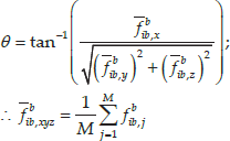
where ϕ is the roll angle, θ corresponds to the pitch angle,
3.1.2. Initialization of the heading angle using a Sun sensor and an inclinometer
As mentioned previously, obtaining absolute heading knowledge with respect to true north on Mars' or the Moon's surface is a difficult problem, due to the lack of conventional heading sensors used on Earth. Solar observation has long been used for navigation purposes as it is a very reliable navigational aid, especially in a planetary environment where there is no atmosphere to hinder observation of the Sun. The heading angle is initialized using a Sun sensor and an inclinometer. Details of the heading estimation algorithm using solar observation are described in Section 4.
3.1.3. Turn-on bias estimation
The IMU signals have some deterministic bias, which must be removed from the IMU's output before using it for navigation. This bias remains constant and is deterministic, but may vary when the IMU is turned on for a new operation. This bias term is easy to calculate if the complete attitude matrix

where

Hence, the turn-on bias of the accelerometer signal can be calculated by equation (8). The turn-on bias on gyro signals is obtained by simply averaging the gyro signals over a static period, as the MEMS gyro does not sense any rotation while stationary, hence:

3.2. Propagation of attitude using gyros
There are three commonly used methods for expressing the orientation of one coordinate frame with respect to the other frame. These three methods are: Euler angles, Direction Cosines and Quaternion-based attitude representation. Among them, the Euler angle method is used most frequently. The common designations of the Euler angles are roll (ϕ), pitch (θ) and yaw (ψ). Its strength lies in a relatively simple mechanization and an easily interpretable physical significance. Its negative attribute is the mathematical singularity that exists when the pitch angle θ approaches 90°. However, for most of the practical platforms in use, especially for planetary rovers, as in this case, the basic assumption is that the pitch angle never approaches this limit. The Euler angle method is explained here in detail. The Euler angles can represent the attitude of a platform from three successive rotations of the navigation frame to the body frame. However, the sequence of rotations is unique to achieve the given final attitude, so the order of rotation must be defined first. In this work, the navigation frame is rotated and fitted into the body frame in the sequence of yaw, pitch and roll. The transformation of the gyro-sensed angular velocity to the Euler angular velocity can be achieved by using the following well-known relation [15],
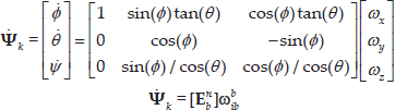
where


where
4. Absolute Attitude Estimation Algorithm Using a Sun Sensor and an Inclinometer
The gyro-based propagation of attitude angles suffers from divergence over time due to the presence of noise in the IMU signal. Therefore, this method cannot be used for attitude estimation in long-term operations. This drift in attitude must be bounded by using some kind of absolute sensor. Absolute sensors, though noisier, have the advantage of long-term navigation stability. Although many kinds of absolute navigation sensors are available in terrestrial applications, there are very few such sensors for planetary rover application. A very reliable and readily available source of navigation information in space is the Sun's radiation, which can be sensed by any light-sensing device and, hence, can be utilized to extract navigation information. In this section the details of the EASI algorithm, which incorporates information from a Sun sensor and an inclinometer, and that produces a sensor's absolute heading angle with respect to true north at a particular time and location, are presented.
4.1. The Sun sensor as a heading estimation sensor
The Sun sensor may be either a CCD- or a PSD-type; the latter has the ability to directly measure the Sun's direction using sunlight intensity. The CCD-type sensors use neutral-density filters directly attached to a wide-angle lens. The camera captures images of the Sun by using an on-board frame grabber and, by applying image-processing techniques, determines the centroid of the processed Sun image. The computer uses this centroid to calculate a 3D ray vector in the sensor's reference frame from the Sun sensor to the Sun, using a mathematical model of the camera [6]. The PSD-type Sun sensors, as used in this work and as is shown in Figure 3, measures the incidence angles of a sunray, called ‘Angle x’ and ‘Angle y’. Angle x is the angle between the z-axis and the projection of a sunray on the x-z plane. Similarly, Angle y is the angle between the z-axis and the projection of a sunray on the y-z plane. The sunlight is guided to the detector through a window above the sensor. Depending on the angle of incidence, the sunlight induces photocurrents in the four quadrants of the detector [16].

PSD-type Sun sensor's (ISS-D60) reference frame and output angles [16]
4.2. Estimation of the absolute angle
To find the rover's heading based on the Sun sensor's output, first of all, the 3D ray vector pointing at the Sun in the Sun sensor frame is determined. It then transforms this ray vector to a gravity-down rover-referenced frame using roll and pitch angles provided by the on-board inertial navigation sensor. In turn, this locally flat frame is used to determine the Sun's elevation and azimuth angles. This forms the set of measurement vectors in a locally flat frame. By use of solar ephemeris data and the equation of time from the Astronomical Almanac [17], the azimuth and elevation of the Sun can also be determined for the given position and time, i.e., longitude, latitude, and universal time (UT). The position and UT are obtained from a GPS receiver on the Earth-based test rover. In actual applications, the global position of the rover is obtained using different means, and the time is the on-board system time. Finally, the heading with respect to true north is computed by use of the known relationship between: (i) the azimuth and elevation of the Sun as computed from the Sun ephemeris data and (ii) the azimuth and elevation of the Sun as determined from the Sun sensor measurements. The whole process of the EASI algorithm is summarized in Figure 4.

Absolute heading and tilt-angle estimation algorithm (EASI) flowchart:
To start with, the first task is to translate the Sun sensor output angles, ‘Angle x’ and ‘Angle y’, to the 3D sunray vector using simple trigonometry. For this, let us assume that the 3D ray vector pointing at the Sun is a unit vector with three orthogonal components (

input the condition of the 3D unit vector,

Then, from Equation (14), × and y components of this vector are found. The 3D sunray vector thus obtained is:

Next, this 3D unit vector is transformed from the sensor frame to the rover frame by using the transformation matrix

One more transformation is required from the rover frame to the flat frame (


Finally, rover heading is obtained in equation (21) using the relation between the Sun's position (azimuth angle) provided by the Sun sensor and the azimuth angle (

Depiction of the relation between rover heading and the Sun's position from ephemeris data and the Sun sensor

4.3. Designing an Attitude EKF for sensor fusion
The attitude of the rover is propagated as given in equation (11) and equation (12) in Section 3.2. In this section, an Attitude EKF is designed by fusing gyro data, accelerometer data and the output of the EASI algorithm. In designing the EKF, the accelerometer data are directly utilized in measurement equations, based on the fact that planetary rovers have very low dynamic acceleration. Hence, both the process model and the measurement model are nonlinear, involving sinusoidal terms. The state vector comprises attitude components (roll, pitch and yaw) and gyro bias terms, i.e.,

The measurement model relates the state vector to inclinometer/accelerometer measurements, as in equation (23).

where,

The whole estimation process of Attitude EKF is presented in the flowchart in Figure 6.

Process flow of Attitude EKF for fusing data from gyros and the EASI algorithm, along with corresponding equations
5. Global Position Estimation Techniques on the Planetary Surface
In this approach, the prediction vectors, namely the Sun's position and the gravity vector, are obtained in the ECEF frame from the Sun's ephemeris data and the gravity model, respectively, as in equation (24).

where
To start with, first the predicted and observed vectors are concatenated and Davenport's q-method [19] is applied. This method is explained with mathematical details in [8,9]. The output of this rotation estimation algorithm is a matrix,
5.1. Global position estimation from the rotation matrix
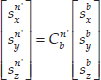
The rotation matrix

Here,

After multiplying equation (26) by

The left-hand side of equation (27) is already known from attitude angles of the vehicle and the estimated rotation matrix
Note that the global position estimated using these methods has an error of hundreds of metres or more, so it is not well suited for incorporation into the navigation system during short operations in order to update the localization of the rover. However, in long-term operations, e.g., over tens of kms, and in the absence of any other accurate global position sensor/system in the planetary environment, this estimated global position is fairly useful for the proposed attitude estimation algorithm (EASI). The overall schematic for fusing relative and absolute sensors is shown in Figure 7.

Sensor-fusion block diagram for the planetary rover's absolute navigation
Note that due to the stop-and-go nature of the planetary rover's motion, this algorithm exploits this situation in updating the relative attitude and relative position using the Sun sensor and inclinometer readings, during both the stop and moving conditions of the rover. This algorithm uses the minimum number of on-board MEMS sensors, which is very important for micro rovers intended to have low weight/volume, consuming less power and, hence, overall reduced mission costs.
5.2. Effect of the global position error on absolute heading angle accuracy
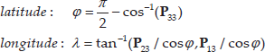
The above method of global position estimation, using only on-board sensors, has errors in terms of kilometres. However, this method can be used for initializing some high-accuracy global position algorithms, e.g., map-matching using DEM and on-board images, etc. Additionally, this global position can be used in heading-angle estimation algorithms. The effect of errors in global position on the accuracy deterioration of heading angle estimation is analysed here. Errors in longitude and/or latitude are introduced, and the corresponding changes in the heading angle are calculated.
Note that a one arc minute (1/60th of a degree) change in latitude corresponds to approximately 1.852km, and a one degree change corresponds to approximately 111.12km on the Earth's surface. The metric change in position is the same as for a latitude change on the Earth's surface. However, in the case of a longitude change, the corresponding change in metric distance depends on the latitude value, as well [20], as shown in Figure 8.

Change in latitude and longitude on the planet's surface. The West-East lines show changes in longitude and the North-South ones indicate changes in latitude.
In Figure 9, the effect of the absolute position error on the heading angle accuracy is shown. The longitude/latitude increased/decreased in increments of a one arc-minute, and the corresponding heading-angle change is computed by the proposed algorithm. The results are shown in Figure 9–10 and in Table 2.

If the longitude/latitude increased or decreased, then the heading angle changes in a linear fashion. The maximum change in the heading angle is less than 3.5° for an error in an absolute position over 200Km.
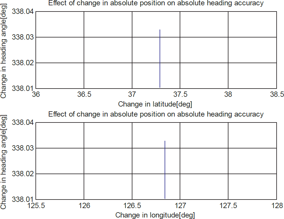
If neither longitude nor latitude are changed, then the change in the heading angle is less than 0.02° (which is very small)
Changes in the heading angle in response to errors in the global position

This analysis shows that errors in the heading bear a linear relationship with errors in the absolute position, and that the maximum error in the absolute heading-angle estimation is about 3.2° for an error in the absolute position of about 220Km (the equivalent of 2° in latitude/longitude). This analysis shows that an absolute position system of moderate accuracy, as described in Section 5.1, can give satisfactory results for absolute heading-angle estimation by the proposed algorithm (EASI) using a Sun sensor and an inclinometer.
5.3. Effect of tilt-angle errors on absolute heading-angles' accuracy
An absolute heading-angle estimation algorithm needs knowledge of tilt angles (roll and pitch) in order to transfer the Sun's position vector to the local flat frame (n'). If there are errors in roll and/or pitch angle, the heading angle accuracy will be affected. Tilt-angle errors may arise from IMU errors themselves and/or gravity model inaccuracies. The gravity model depends on latitude and height accuracies and, as observed in the previous section, accurate knowledge of the latitude may not be expected in planetary environment. Hence, errors in tilt angles are always inevitable.
In this section, the effects of errors in the roll/pitch angle on changes to the heading angle are analysed. The procedure is that the roll and pitch angles are incremented/decremented by 0.5°, and the corresponding change in the heading angle in the EASI algorithm is recorded.
It is observed from Figure 11 that the maximum heading error that occurs is less than 1°, with tilt errors as high as 2°. Hence, it is concluded that the designed heading estimation algorithm (i.e., EASI) is robust against tilt angle errors.
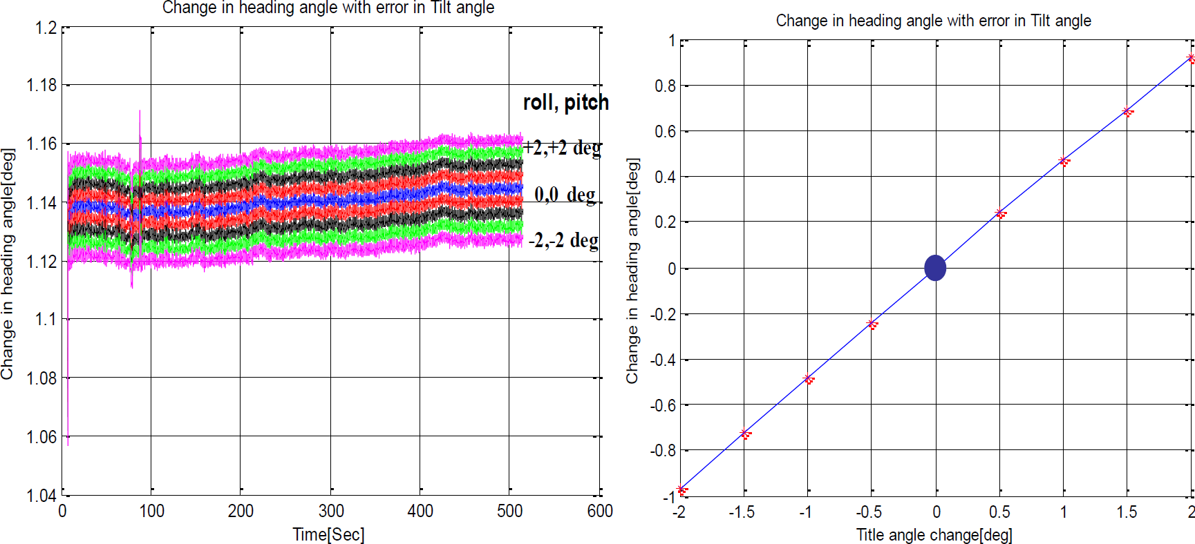
Effect of a tilt angle (roll and pitch) error on the heading angle's accuracy. It is observed that heading angle changes are very small, even if the tilt angle error is 2°.
6. Experimental Methodology and Results' Discussion
6.1. Hardware description of the navigation sensor suite for a micro planetary rover
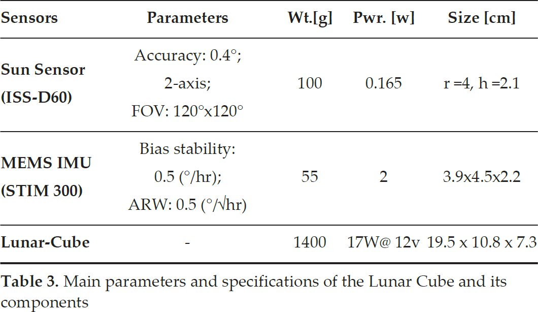
A prototype navigation unit, dubbed ‘Lunar Cube’, has been developed in KITECH, as shown in Figure 12. It uses low-cost, low-weight/volume MEMS-type sensors with low power considerations, which are necessary parameters for a micro planetary rover that would be deployed in future missions. The sensors used in this navigation unit include: ISS-D60 (Sun sensor) and STIM300 (IMU), based on MEMS technology and a NovAtel GPS unit for location and timing information for Earth-based testing. The Sun sensor is a PSD-type sensor with two orthogonal axes and a wide field of view. The IMU consists of a 3-axis accelerometer, 3-axis gyros and a 3-axis inclinometer, with on-board calibration and temperature-compensation routines. The data from the Sun sensor are logged at 10Hz, and those from IMU at 125Hz. The main parameters of these sensors are given in Table 3. The Lunar Cube consists of an Intel NUC D5250WYB as a sensor-system processor. This system is equipped with an i5-4250U CPU, an 8GB SO-DIMM memory and a 128GB m-Sata SSD. The operating system is Ubuntu 12.04, and our data-acquisition program runs on this system. The power consumption is 12W when the system is in an idle state, and 17W at full load. This system can run using an external or an internal battery pack.

Lunar Cube: A prototype lunar rover-navigation unit designed in KITECH using MEMS sensors
Main parameters and specifications of the Lunar Cube and its components
6.2. Experimental set-up and results' discussion
For evaluation of our proposed algorithm (EASI) for estimation of absolute navigation information for a planetary micro rover, almost all possible motion scenarios commonly encountered by planetary rovers as shown in Figure 1 are considered. These include:
The long time (e.g., hours) spent in a stationary state: planetary rovers remain stationary most of the time unless they are commanded to perform some task or move forward.
Turn-in-place (TiP) motion: this is a very common motion type on a planet with many obstacles that have not been seen before. The rover has to avoid them by performing a turn-in-place motion to reach the goal while using the minimum amount of energy and time.
Linear and curved path motion: planetary rovers are commanded to move forwards by a few centimetres, to look around and then to take a curved path around any encountered obstacle or target rock in order to take the appropriate action.
For (a), the rover was stationed at a fixed position (longitude: 126.841833° and latitude: 37.293353°) and in a particular direction on 27th October 2014 for about 2.5 hours, and data from the STIM300 IMU, the Sun sensor and the GPS were captured. The roll and pitch angles were 4.5° and 6°, respectively, during this test. The main purpose of this test is to check the long-term stability of the heading estimation algorithm using the Sun sensor and an inclinometer using the EASI algorithm, with position and time stamps taken from the GPS. In the actual planetary rover, time stamps may come from an on-board clock and the position is the last best estimation of the global position. Results are displayed in Figures 13–17. Angles x,y are the Sun sensor's raw output, which is then translated into a sunray unit vector pointing to the Sun. This sunray vector is then transformed to the local flat frame with the knowledge of roll and pitch angles derived from the inclinometer, or can be taken from the Attitude EKF's output. The heading-angle estimate remains constant around the reference angle of 63° with a standard deviation of 0.61°, which shows the long-term stability of this algorithm. Figure 16 and Figure 17 show the comparison of the Sun's elevation and azimuth angles as predicted from the Sun's ephemerides and those calculated using the EASI algorithm.

Output (Angle x) of the Sun sensor during the 2.5 hour static test

Output (Angle y) of the Sun sensor during the 2.5-hour static test

The rover's heading angle from the EASI algorithm during the 2.5 hour static test. The heading angle remains constant with a standard deviation of 0.61°.
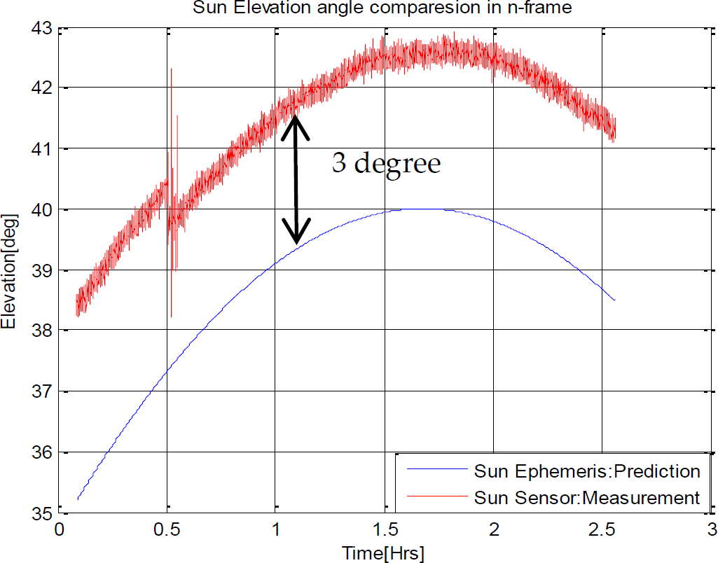
A Sun elevation angle comparison between the Sun's ephemeris data and the Sun sensor's actual measurements in the n-frame. There is an offset of 3° in elevation due to the atmospheric effects, called the Albedo Effect, which is encountered only on the Earth.

A Sun azimuth angle comparison between the Sun's ephemeris data and the actual Sun sensor's measurements in the n-frame
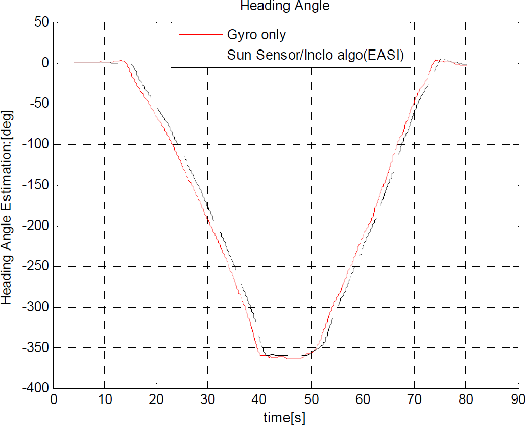
To test the TiP motion scenario (b), the sensor module is continuously rotated through 0~360°: once counterclockwise (CCW) and then clockwise (CW), as shown in Figure 18. In test#1, the sensor plate is kept levelled to mimic the TiP motion on a smooth surface. However, to simulate the TiP motion on rough terrain beneath the rover, the sensor plate is deliberately tilted in the roll and pitch angles while rotating it though 0~360° and back: again, first CW and then CCW in test#2. In test#3, the sensor plate is rotated in steps of 30°, both CW and CCW, and the estimation of the EASI algorithm is compared with the reference angle. The reference angles are obtained from a Goniometer, as set-up in Figure 21. Note that the gyro-only heading diverges by about 3° as expected, but also that the EASI algorithm gives very consistent absolute heading angles with an error of 0.1° in this test. The heading estimation results in three TiP tests are displayed in Figures 19, 20 and 22.

The turn-in-place (TiP) motion, both CW and CCW, through 0~360 °
Continuous TiP test#1: CCW and CW through 0~360° with a mild tilt (±5°) during rotation

Continuous TiP test#2: CCW and CW through 0~360° with a high tilt (±30°) during rotation

Goniometer with a Lunar Cube on top; a set-up for the step-wise TiP test

Step-wise TiP test#3: CW and CCW through 0~360° and back in steps of 30°

Zoomed view of the end-point attitude in TiP test#3. The divergence in the gyro-only solution is clearly shown, whereas the EASI algorithm produces a non-diverging, yet noisy, heading angle. The attitude of the EKF gives a stable attitude at a high update rate.
Scenarios (a) and (b) include a static type of motion but scenario (c) is a dynamic test of the rover. In this test, we moved the sensor module slowly (e.g., 2cm/sec) for about half an hour in both straight and curved paths, with arbitrary roll, pitch and heading angles and frequent stop and go conditions. The sensor module was fitted on the top of a hand-driven cart with small metallic wheels, which caused much vibration during the dynamic test. The Sun radiation obstruction scenario is also considered and it is shown that the Attitude EKF, which fuses data from the gyro and the EASI algorithm, continues to estimate the heading angle even if the Sun's radiation is below the threshold of the Sun sensor (300W/m^2). We compared the accuracy of our attitude estimator with that of an off-the-shelf AHRS from Microstrain Inc., which has an accuracy of 0.5° in static and 2° in dynamic conditions. The divergence in a gyro-only solution is evident in Figures 24–26. The Attitude EKF continues to estimate the correct heading even in the absence of the Sun's radiation. The Sun's radiation obstruction is seen in Figure 27. The numerical results for the attitude angle's divergence at the end of the dynamic test are given in Table 4. One particular feature of the Attitude EKF is that it continues to estimate the rover's attitude even if the Sun's radiation falls below the sensor's threshold. The EASI algorithm stops in this case, but the Attitude EKF continues to estimate the accurate attitude, both in static and dynamic conditions of the rover. The EASI algorithm is a one-shot algorithm, which can work at 10Hz (the Sun sensor's output data rate).

Roll angle estimated by the Attitude EKF
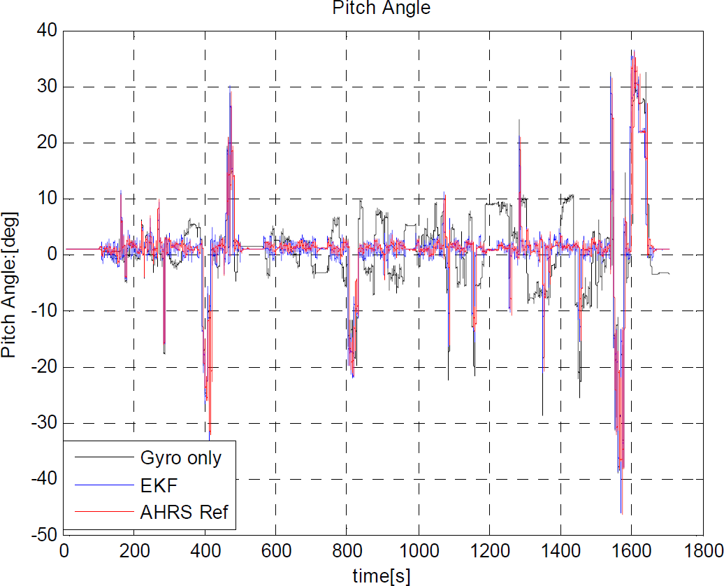
Pitch angle estimated by the Attitude EKF

Rover-heading angle estimated by the Attitude EKF and the EASI algorithm

Sun radiation values during a dynamic test lasting half an hour. The Sun's obstruction causes the radiation to fall below the sensor's threshold (300W/m^2).
Comparison of attitude estimation during a half-hour dynamic test

7. Conclusion
In this paper, we presented an algorithm for gaining absolute navigation information, especially roll, pitch and heading estimations, using MEMS sensors in planetary environments. First, the raw data from an inclinometer and the Sun sensor are used in the EASI algorithm to produce the absolute heading, roll and pitch angles. Next, the output of this algorithm is fused with the IMU in the framework of the EKF to output more accurate and stable attitude estimates with a high data rate. A sensitivity analysis of the designed algorithm is performed in order to check the maximum error in response to errors in the absolute position and the tilt angle. Finally, the algorithm is tested under different motion scenario, e.g., a long-time static condition, a turn-in-place motion and motion in straight and arbitrarily curved paths, simulating planetary rover motion scenarios. The results of the different tests demonstrate that the designed algorithm is robust to errors in both longitude/latitude and roll/pitch angles, and also works well in all rover motion scenarios commonly encountered in planetary environments. As a future research direction, this attitude estimation algorithm can be combined with wheel encoders to produce position tracks, and can be tested under various environmental conditions for planetary rovers' full navigation. A visual odometry (VO) module may be incorporated as an alternate attitude and position estimator in future works.