
Abstract
With high speed and accuracy the parallel manipulators have wide application in the industry, but there still exist many difficulties in the actual control process because of the time-varying and coupling. Unfortunately, the present-day commercial controlles cannot provide satisfying performance for its single axis linear control only. Therefore, aimed at a novel 2-DOF (Degree of Freedom) parallel manipulator called Diamond 600, a motor-mechanism coupling dynamic model based control scheme employing the computed torque control algorithm are presented in this paper. First, the integrated dynamic coupling model is deduced, according to equivalent torques between the mechanical structure and the PM (Permanent Magnetism) servomotor. Second, computed torque controller is described in detail for the above proposed model. At last, a series of numerical simulations and experiments are carried out to test the effectiveness of the system, and the results verify the favourable tracking ability and robustness.
1. Introduction
The parallel manipulators have potential advantages in terms of stiffness, accuracy, high speed, and payload over their serial counterparts. The parallel manipulators have wide applications, such as Pick and Place operation and so on. The way to fulfill the advantages on excellent high-speed and high-precision control performance of the parallel manipulators has become one of the key research points of the scholars and engineers.
The dynamic model of the parallel manipulators is a kind of non-linearity with characteristics of time-varying and coupling [3]. And most nonlinear mechanical systems comprise driven motors, coupling gears and the nonlinear mechanism [2]. Note that the complex motor-mechanism coupling modeling will cost a lot of time, in addition, control methods also influenced the control performance dramatically, so how to design the model based controller is very important to fulfill the performance of mechanisms. In the history of the control method development, it can be divided into classical control algorithm, modern control algorithm and intelligent control algorithm. The classical control, such as simple PD and PID linear control, is simple but not good performance for nonlinear system. The modern control like motion control is used more and more because it is simple in the structure and better performance in control. The intelligent control can prove the best control performance but it needs a lot of experience and is always hard to design. In the nowdays, many modern and intelligent control techniques have been developed for the nonlinear mechanical system [9], such as adaptive control, fuzzy control, sliding mode control, computed torque control and neural network control. Fuzzy control is a valid method but difficult to design and analyze suitable fuzzy rules. The artificial neural networks control is such a method that has the capability of learning from processes. And it does not need the control model, but is difficult to design the number of middle layer of network. Sliding mode control is a new method but some bounds on system uncertainties must be preestimated. Among these algorithms, the motion control, like computed torque control, is a high-performance rotational or translational control of torque and speed [5]. The computed torque control is utilized to linearize the nonlinear dynamic of manipulator [4]. It can provide excellent tracking performance by considering nonlinear compensations with the precise dynamic model [1]. Consider the sensitivity to the parameters and disturbance, several computed torque controllers have also tried to circumvent the problems of uncertainties using some adaptive techniques [6].
Usually, the non-linear motor-mechanism coupling dynamics of manipulator is not under fully consideration in most dynamic modeling. For example, in the design of a hybrid controller with neural network [8], part of the motor dynamics is proposed for the hybrid controller. In addition, the other way is that the model was often equivalent by scholars to the robot model in [7]. In one word, the above models were about the simple mechanisms only, and among these models, the mechatronic dynamic modeling of parallel system has been discussed but was very scarce.
The structures of paper are organized as following: In part 2, the 2-DOF parallel manipulator called Diamond 600 is introduced in brief. In part 3, the mechanism and motor dynamic models are deduced. With the equivalent torque, the motor-mechanism coupling dynamic model is fomulated. The controller employing computed torque algorithm is also described in detail for coupling model in this part. The simulations and experiments are provided in part 4 and 5 respectively. The last part is the conclusions.
2. System Description
Fig.1 depicts 3D solid modeling of a high speed parallel manipulator known as the diamond 600 for Pick and Place operation. The manipulator consists of a static platform, a moving platform and two kinematic chains. The two parallelogram strut structures consist of the framework, input link, passive input link, bracket, and bracket, inner distal link, moving platform, outer distal link. All the components are connected through the revolute joints.

Solid model of the parallel manipulator
3. Motor-Mechanism Dynamic Model and Control
The control block diagram is shown as Fig. 2. The whole system can be divided into two parts. One is the motor-mechanism coupling model and the other is computed torque controller. From the desired values in the workspace and the inverse kinematic model, the ideal angular displacement, velocity and acceleration can be got as a reference values. The errors between the actual condition and the ideal condition can be regarded as the input of the controller. The ideal voltages and currents can be achieved using the state equations in the ideal condition at the same time. The compensations can be implemented in the inner loop, and the accurate outputs can be calculated by the precise coupling model.

Control block diagram of the system
A. Mathematical Model of Diamond Manipulator
Because of the identical and parallelogram strut structure of the actuated input links and distal links, the original model can be simplified into a 2-DOF with 5 bar manipulator system shown in Fig. 3 during kinematics analysis.
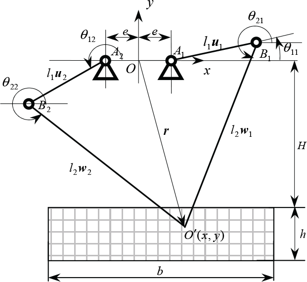
Sketch of the locomotion
The inverse kinematics is to determine the rotation angular angle θ1i (i = 1,2) with the position vector r = (x y)T of the moving platform reference point O′.

where l1, l2,
The

Take time derivation on each side of (1), leads to

where
Take dot product of

where
Differentiating (2) with respect to time yields the acceleration
The inverse dynamic modeling which is the foundation of controller design, is to determine the applied force or power of the servomotor with the inertia and moving parameters of the parallel manipulator.
The following assumptions are made to simplify the model. The movement pairs are ideal ones that there is no energy dissipation caused by the friction; The moments of the inertia of the distal and passive input links are negligible because they are made by slender bars; Their masses are divided evenly and concentrated at two endpoints B i and O′; As the bracket and the moving platform undergo pure translation, the motions of any points on these components can therefore be represented by those of B i and O′ respectively.
Thus, considering the joint force, gravity and inertia force gives the following equation using the Virtual Work Principle while I
A
is the equivalent rotary inertia of mechanism.
Substituting
Substituting (3) and (4) in to (6) yields the relationship of the torque and the angular displacement as following:

B. Field-Oriented Control PM Synchronous Motor Modeling
The 3-phase alternating current servomotor is widely used in the industry, but the parameters of the servomotors, such as voltage, current and so on, are time-varying in real work situation. They are hard to describe in the coordinate system. Fortunately, the Park Transform can be employed to transform the 3-phase parameters into the equivalent parameters in the arbitrary coordinate system. The coordinate system is established on the rotor as shown in Fig. 4.

Coordinate system o – dq of servomotor
Field-orientated control is a technique that provides a decoupling method. It can change the currents into two components of stator current: one producing the air gap flux and the other producing the torque. Therefore, it provides independent control of torque and flux, which is similar to a separately excited DC motor. Therefore, with the implementation of the Field-orientated control method, the PM synchronous motor drive system can be simplified as a DC motor, as is shown in Fig. 4.
According to the equivalent relationship of Park Transform, we can obtain

where

Because the resistances

where L l is the leakage inductance and L m is the magnetizing inductance of each phase. M = −1/2L m and L = L l + L m .
Applying the KCL (Kirchhoff Current Law) and ignoring the influence of the d axis on q axis, we can achieve the voltage U
q
in the q axis.

where

And the output torque of the motor, which is determined by the control current, can be expressed as

where K m is coefficient of the relationship between the torque and the current, J m is the rotary inertia of the rotor.
Considering the torque of the bearing τ
B
= Bω
m
which B is the damping coefficient, the torque of the reducer τ
R
which n is the reduction ratio and the torque of the friction τ
L
, ω is the angular velocity of mechanism, the total output torque is

C. Motor-Mechanism Coupling Model
From equations (12) and (7) leads to

Combined with the voltage equation (10), suppose x1, x2, x3 are the angular displacement, velocity and current respectively. V is the corresponding control voltage. We can deduce the state equations as following


where
D. Design of Computed Torque Controller
The manipulator's dynamics can be expressed as

Writing in the standard form
where

Suppose the desired trajectory

Consider the control law corresponding to a computed torque scheme with nonlinear gain matrices as

where
4. Simulation
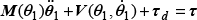
By use of Runge-Kutta fourth order numerical integration method, state equations are solved for the motor-mechanism coupling system. For numerical simulations, Table 1 shows the geometry and inertia parameters of the parallel manipulator. Table 2 shows the parameters of Fuji AC servomotor of GYG152CC2-T2E and its driving system. There are two reducers between the motors and the mechanism.
Geometry and inertia parameters of the mechanism
Parameters of the GYG152CC-T2E servomotor

A series of simulations are conducted to demonstrate the performance of computed torque control algorithms. In order to enable the end-effector to pick an object from one place to another, the desired trajectory is preset as three straight lines which are vertical to each other in Fig.5. The acceleration mode is in cycloid pattern. Under the control of the computed torque algorithm, the performances of manipulate are shown in the Fig. 6–10..

Trajectory of end effector in the workspace

Errors of angular displacement
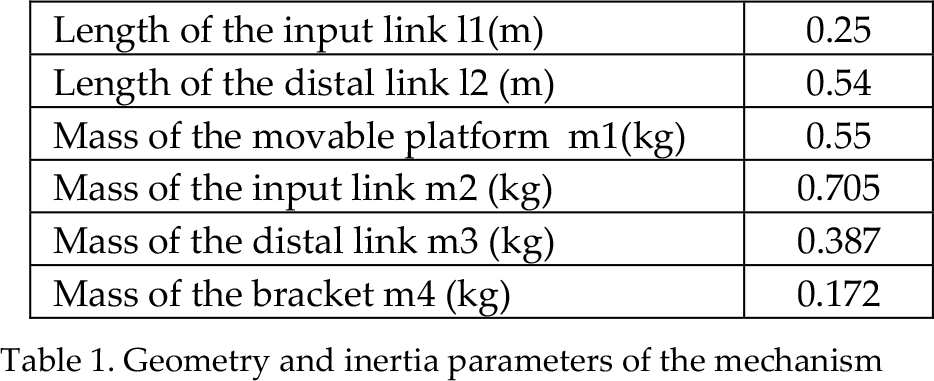
Errors of angular velocity

Errors of the trajectory in workspace

Errors of driving torque

Currents of the 3-phase of the servomotor
Fig.6 shows the manipulator's errors of trajectory in the operation space. There are initial errors, and the errors reduce to very small values in a short time. In the middle of the trajectory, the errors are a little larger because of the highest speed. But the last point in trajectory can be accurately tracked because the errors of angular displacement converge to small value. It is very important to the Pick and Place operation. In the Fig. 7, the initial errors can be cancelled out quickly. With the accurate tracking of the angular displacement, the angular velocity can be tracked in small errors too. At the end of the processes, the errors are almost zero. In Fig. 8, it depicts the errors of the manipulator in the workspace. Based on the errors of the angular displacement and the angular velocity, the larger errors appear in the middle segment of the whole trajectory and the minor errors at the end of the movement. Fig. 9 describes the torque errors. The actual torque follows the desired torque when it is in the low speed, and the errors become large with the increasement of speed. And under the control effect, the errors can be compensated and the end torque can be considered as the ideal one. All of the results can provide reliable tracking performance of the designed control algorithm. The small end errors are suitable to the operation such as Pick and Place which requires high end precision. Fig. 10 depicts the 3-phase currents of the servomotor as the effect of control. There is 120 degree discrepancy in the 3-phase currents. In the middle of three segments, the currents are big because of the high speed and control torque. The highest speed in the segment 2 is higher than the other two, so the currents are larger than the ones of the other two segments. In addition, they are not equal to each other because they have to transform into the current in q-axis.
5. Implement
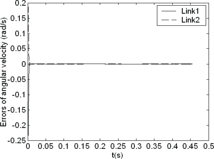
The proposed controller has been applied to the Diamond 600. The experimental equipments and schematic diagram of the system are shown in Fig. 11. The structures of PC+PCI7344+Servomotor GYG152CC2-T2E are chosen as the control hardware. The UMI (Universal Motion Interface), software of NI Measurement & Automation Explore and LabVIEW are also chosen to build up the control system. The servomotors are set in the torque mode. PC computes sends control signals to the servo drivers through the PCI7344 and UMI. The feedback signals such as angular displacement and velocity are acquired from the encoders through analog to digital conversion. The angular displacement and velocity are shown in the Fig. 12 and 13 respectively.
Photograph of experimental equipments

Displacement of the servomotors

Angular velocity of the servomotors
Fig.12 and 13 show the real angular displacement and velocity generated by the servomotors. We can see that there are no movements at the beginning but there are disturbances as the initial errors from 0.11s, and it will take some time to decrease the disturbance and overcome inertia from the 0.11s to 0.15s. The errors of the angular displacement and velocity are a little big at this phase. We also find that there are still big errors around 0.25s and 0.61s because the directions change at these moments. The errors in the middle are bigger because of the higher angular velocity, but end errors of the angular displacement and velocity convert to zero. The precise end tracking ability is suitable for the Pick and Place operation.
6. Conclusion
The investigation proposes a model based controller for a high speed parallel manipulator. Combined mechanism dynamics with the motor dynamics, the precise and feasible motor-mechanism coupling model can be obtained. Model-based computed torque controller is also proposed for the high performance. It can get rid of the initial disturbance and provide the small steady end errors for the operation. The simulation and experiment also verify the validity of the controller, along with the favourable tracking ability and robustness.
Footnotes
7. Acknowledgements
The research is supported by the NFSC, grant No. 50375106, the State Scholarship Fund, Grant No. 2004812032.