
Abstract
The thermal expansion phenomenon of bearings happening on a motorized spindle has a great effect on its dynamical properties. Hence, there is a vital need to analyze the relationship between its cooling condition and dynamical behaviors for the system. A thermal–mechanical coupling model of a motorized spindle system is presented in this article, which consists of three coupling sub-models: bearing, thermal and spindle dynamical model. The bearings, taking the thermal expansion into count, provide the shaft with support stiffness which influences the spindle dynamical properties. And their power loss is one of the main heat sources of the system while the other one is from the motor. In the thermal model, the cooling condition and heat generation jointly determine the temperature rise and thermal expansion. Thus, all of the sub-models interact and the system becomes an integrated thermal–mechanical coupling model. The proposed model is investigated by a solution procedure and validated experimentally. And the effects of the rotational speed, cooling water flow rate and oil-air pressure on the spindle dynamical properties are provided by this mathematical model as well as the experiments. The good agreement of results from them indicates that this model is capable of predicting the dynamical properties of the motorized spindle system. Then some feasible methods to improve the dynamical behaviors of the system are obtained.
Introduction
With the rapid development of high-speed machining, which can dramatically increase productivity and reduce production costs, the motorized spindles have become the core components of computer numerical control (CNC) machines 1 and their failures caused by dynamical factors are very common. 2 In the research of the motorized spindle, the thermal effect, especially on the dynamical properties of a system, is always the emphasis and difficulty. Therefore, there is a necessity of comprehensive and in-depth study on the dynamical properties analysis of motorized spindle under the thermal effect.
In the early analysis of thermal model for a motorized spindle system, the effect of it usually did not focus on the dynamical properties of the system.3–6 Pahk et al. 3 found that the thermal behaviors of motorized spindles play an important role in successful operation as they affect the machine tool accuracy. Bossmanns and Jay4,5 established a power flow model, which considered the power loss of motor, bearing and air friction at high-speed-operation conditions, to analyze the temperature rise characteristics of motorized spindles. Recently, some advanced theories have been used for the thermal model; for example, Xu et al. 6 developed the thermal model of a spindle system considering the thermal contact resistance at the solid joints based on the fractal theory and analyzed the temperature rise and thermal expansion of the system.
The dynamical properties analysis for the motorized spindle system, not considering the thermal effect, has been researched in some papers.7,8 The dynamical model of motorized spindle has been changed from the simple spring–rotor system with constant spring stiffness and ideal shaft shapes 7 to the advanced dynamical model 8 considering the centrifugal force and gyroscopic moment effects in the bearing model 9 and the shear and gyroscopic effects in the shaft model. 10 Recently, based on the methods mentioned above and considering the thermal effect, Li and Shin11,12 established an integrated dynamical thermo-mechanical model of high-speed motorized spindles to analyze the effect of the axial thermal expansion of the shaft on the bearing preload change and spindle dynamical properties.
Some researches mentioned above predicted the thermal and dynamical properties for a spindle system, but did not consider the coupling relationship between them. And the researches considering the coupling relationship had neglected the effect of thermal expansion on the geometrical parameters of bearings. Therefore, this article presents a thermal–mechanical coupling model for dynamical properties analysis of a motorized spindle system. Applying this model, the temperature rise at the outer rings of front and rear bearings, thermal expansion amounts of bearing geometrical parameters, bearing stiffness, spindle stiffness and natural characteristics of a system have been obtained under different operating conditions. Then some experiment setups are designed to validate the results of this theoretical model. The good agreement between the calculated results and test data indicates that the model is capable of accurately predicting the dynamical properties of the motorized spindle system.
Thermal–mechanical coupling model
The schematic of the motorized spindle system is shown in Figure 1. The shaft is supported by two pairs of angular contact ball bearings with double back-to-back arrangement. The front bearings and rear bearings are simultaneously preloaded by a series of compressive springs, which are set at the end face of the axial movable rear bearing pedestal, to reduce the effects caused by thermally induced preload. The bearings are individually cooled by oil-air lubrication. An asynchronous induction motor, adopting U/f control method, rated at 6 kW maximum power and up to 60,000 r/min, is located between the front and rear bearings. And the curves of power, rotational speed and torque of this motor are shown in Figure 2. The motor stator and front bearings are cooled by water. A test bar, with the same size as that of a grinding wheel, is designed and mounted on the shaft. The outside surface of housing, with smooth cylindrical shape, is easily fixed on the workbench.
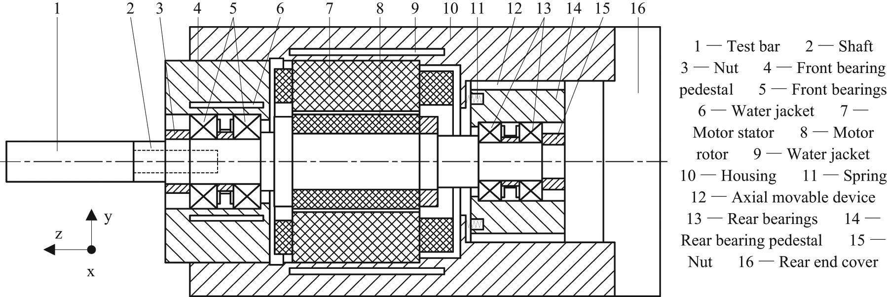
Schematic of the motorized spindle system.
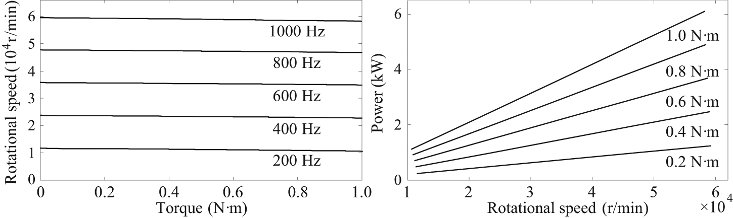
Curves of power, rotational speed and torque of motor.
The thermal–mechanical coupling model of this motorized spindle system is shown in Figure 3 to describe the coupling relationship. The bearings provide the shaft with support stiffness in five degrees of freedom without the degree of freedom of around z-axis. Hence, the variation of bearing stiffness has a great effect on the dynamical properties of shaft. Meanwhile, the power loss of the bearings is one of the main heat sources of the system while the other one is from the motor. The temperature rise and thermal expansion caused by the power loss influence the geometrical parameters of bearings which determine their support stiffness for the shaft. Therefore, all of the sub-models interact and the system becomes a comprehensive thermal–mechanical coupling model.
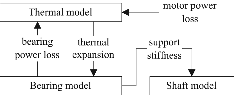
Thermal–mechanical coupling model of the motorized spindle system.
Bearing stiffness
The basic bearing model used in this article is adopted from Li et al. 9 and the modified model takes the effect of thermal expansion of bearing rings and balls into account. The thermal expansion of inner ring, outer ring and ball changes the geometrical relationship of bearing, which determines the parameters of balance equations of the bearing balls and inner ring. 9 Based on the bearing raceway control theory and Hertz contact theory, the running state of bearing can be obtained by solving the balance equations mentioned above. From the results of those equations, the relationship between the load and the displacement of the bearing inner ring can be expressed as
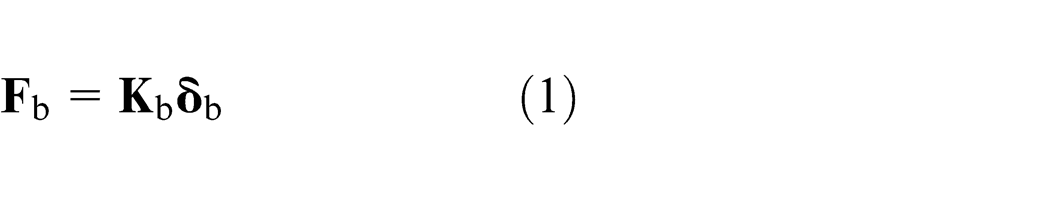
where
Thermal model
Heat source
A motorized spindle, running at high speed, will produce a large amount of power loss inevitably. From the results of bearing equations, the bearing power loss can be obtained from equation 51 of Li and Shin. 11 Besides, the other power loss from the motor can be obtained by using the method in Chen et al. 14
Thermal boundary condition
The thermal boundary condition of the motorized spindle system mainly includes the convection heat transfer between the motor stator and cooling water, front bearing pedestal and cooling water, air gap heat exchange between the motor stator and rotor, heat dissipation at the motor rotor, shaft end and shaft moving outer surface, and convection heat transfer inside the bearings based on oil-air lubrication.11,12 Since the option for high-speed bearing is only the oil-air lubrication and the main factor influencing the convection heat transfer inside bearings is the oil-air pressure, in this article, only the oil-air pressure and coolant flow will be experimentally studied.
Thermal expansion
In the little range of thermal expansion, the thermal expansion amount is approximately proportional to temperature rise and the relationship can be expressed as 13
where
Spindle dynamical model
The test bar and shaft are consolidated together by the threaded connection, and it can be assumed that they have the same degrees of freedom at those nodes, which is called the rigid connection. The machine parts mounted on the shaft, including bearing inner rings, motor rotor and nuts, are assumed to have the same degrees of freedom with the shaft's nodes, and modeled as rigid disks with gyroscopic moment considered, applying the principle that keeping the constant inertia. And it is called the node with a disk. The shaft and pedestals are connected by bearings, which are simplified as nonlinear springs to support the shaft in the axial direction (z-axis), radial direction (x-axis and y-axis) and angular direction (around x-axis and y-axis). The rear bearing pedestal is fixed in the radial direction and angular direction but not the axial direction because of the axial movable device and it is connected with the fixed housing by springs. Therefore, the shaft is modeled as a finite element dynamical model, which is shown in Figure 4. Then, assembling the equations of shaft, bearings and bearing pedestals, 10 considering the effect of system damping, the equilibrium equation for the motorized spindle system is obtained
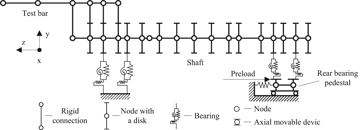
Dynamical model of the motorized spindle system.
where
which is used for the analysis of spindle stiffness.
Experimental setup
In order to analyze the dynamical properties of the system based on the thermal–mechanical coupling model, some corresponding experimental studies, under different operating conditions, on a 120MD60Y6-type motorized spindle, have been carried out. The experimental setup for the excitation test is shown in Figure 5 and the signals of excitation force and vibration acceleration at the tip of the test bar, with rotational speed being 0, can be measured synchronously for the frequency response function (FRF) analysis. The experimental setup for the vibration displacement and temperature rise test, shown in Figure 6, consists of the electrical parameters control and test system, temperature rise test system and vibration displacement test system. The supply voltage, current and excitation frequency of the motor, temperature rise at the outer ring of front bearing and rear bearing, vibration displacement at the tip of test bar in the radial and axial direction, with different rotational speed, can be directly measured by the sensors installed on the spindle. And all the data from those tests can be sent to the computer and processed by corresponding software.
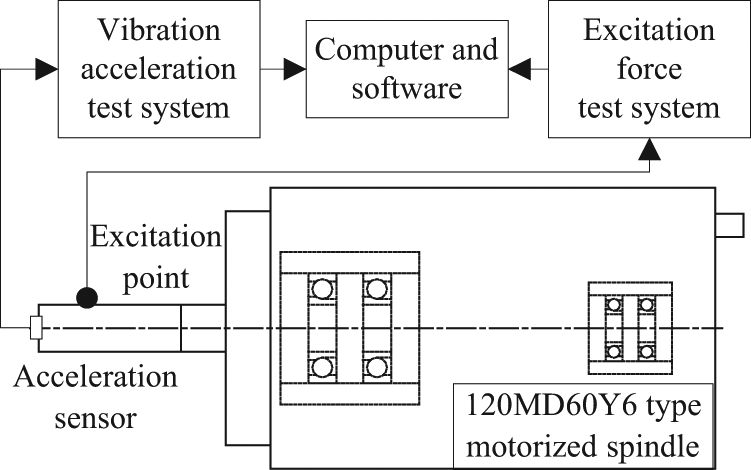
Experimental setup for the excitation test.
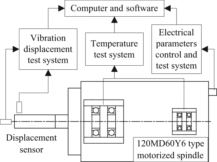
Experimental setup for the vibration displacement and temperature rise test.
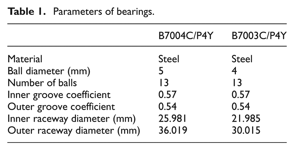
The types of the front and rear bearings are B7004C/P4Y and B7003C/P4Y, respectively, and the parameters of them are shown in Table 1. The springs can provide the bearings with constant preload of 80 N. The cooling water flow rate is 1.0–3.0 L/min. The supply oil-air pressure is 0.2–0.4 MPa. The environment temperature is 22.1 °C.
Parameters of bearings.
Analysis and validations
Figure 7 shows the calculation flow chart of the thermal–mechanical coupling model. To begin with, by solving the bearing model, using the Newton–Raphson iteration method, the bearing power loss and bearing stiffness can be obtained. Then, based on the spindle dynamical model, the natural characteristics of the system, using subspace iteration method, will be analyzed. Meanwhile, the temperature distribution and thermal expansion of the system can be obtained from the solution of thermal model. Then the updated bearing geometrical parameters based on the thermal expansion can be determined to resolve the bearing model. Repeat these steps until the solution of thermal expansion meets the convergence precision.
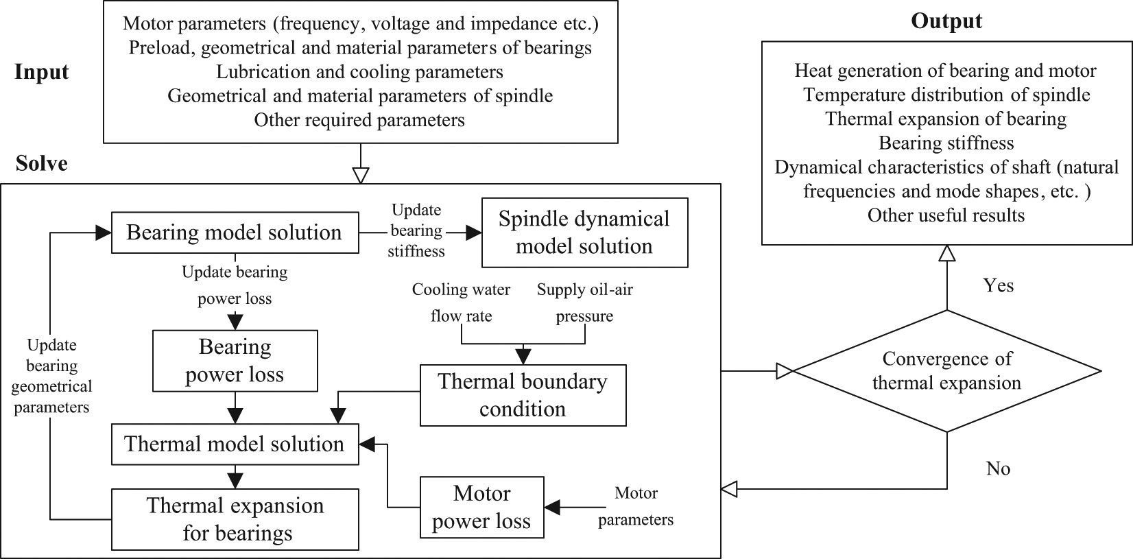
Calculation flow chart of the thermal–mechanical coupling model.
Analysis of natural modal shapes
Since the natural modal shapes of the system with different temperature distribution, thermal expansion or rotational speed are almost no change, there is an analysis of natural modal shape only when cooling water flow rate is 2.0 L/min, oil-air pressure is 0.3 MPa and rotational speed is 36,000 r/min. Figure 8 shows the first and second order natural modal shapes of radial vibration. The first is the swing vibration of the test bar with little relative vibration amplitude at the shaft. And the second is the vibration of the test bar and the shaft with one vibration wave at the shaft. Figure 9 shows the first and second order natural modal shapes of axial vibration. And both of them are rigid-body vibrations happened at the test bar, shaft and rear bearing pedestal. The first is the axial vibration happened at the test bar and shaft, while the relative vibration amplitude of the rear bearing pedestal is nearly zero. Compared with the first natural modal shape of axial vibration, the second is just opposite.
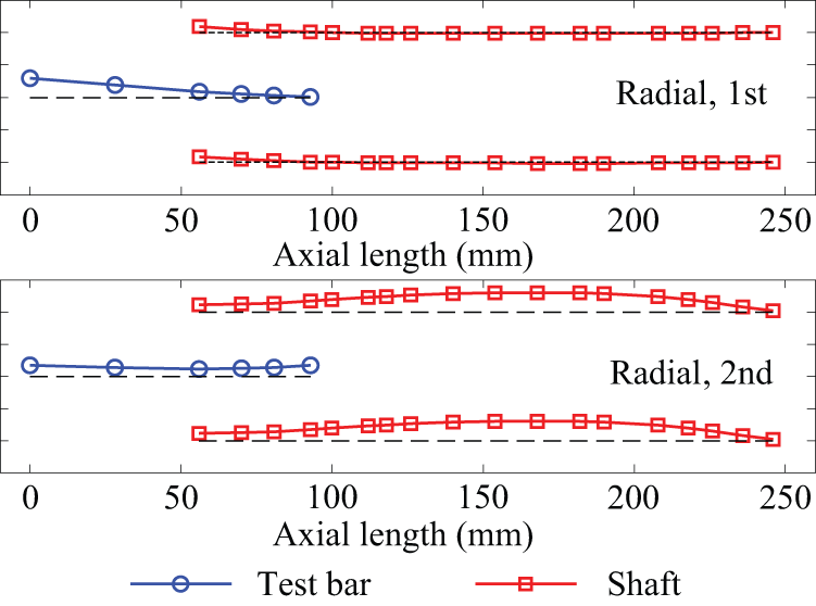
Natural modal shapes of radial vibration at 2.0 L/min, 0.3 MPa and 36,000 r/min.
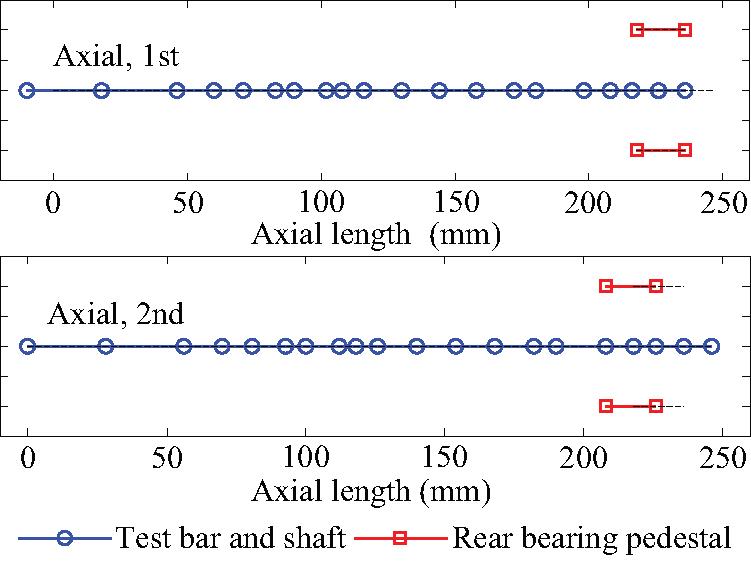
Natural modal shapes of axial vibration at 2.0 L/min, 0.3 MPa and 36,000 r/min.
Analysis and validations for the excitation test
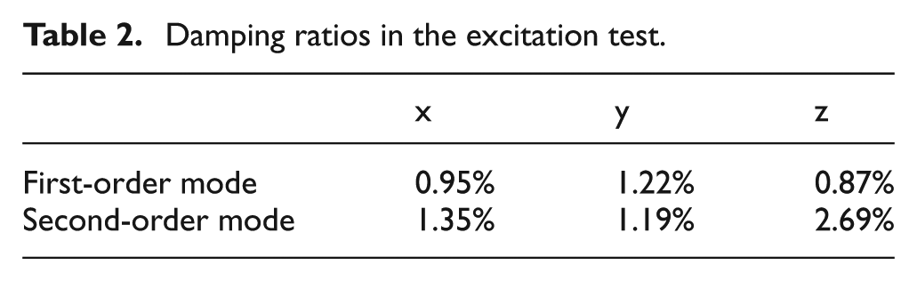
In the excitation test, the rotational speed is 0 and there is no temperature rise and thermal expansion. Figure 10 shows the tested and calculated FRFs of the radial (x and y direction) and axial (z direction) vibration at the tip of the test bar. Within 0–3000 Hz frequency range, there are two amplitude peaks at the natural frequencies in the radial direction, which correspond to the two natural modes of radial vibration. Theoretically, the radial FRFs in the x direction and y direction should be absolutely identical. However, the tested data have some differences between them because of the unsymmetrical structure of the experimental setup. Likewise, there are two amplitude peaks at the natural frequencies in the axial direction which correspond to the two natural modes of axial vibration. Besides, there is an amplitude peak at about 2000 Hz, and it is probably caused by the effect of second-order radial natural mode. The modal damping ratios obtained from these tests are listed in Table 2 and used for the calculations in subsequent studies.
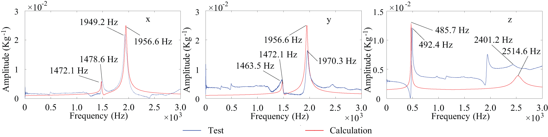
Tested and calculated FRFs of radial and axial vibration at the tip of the test bar.
Damping ratios in the excitation test.
Analysis and validations for temperature rise and thermal expansion
As shown in Figure 11, when the cooling water flow rate is 2.0 L/min, oil-air pressure is 0.3 MPa and rotational speed is 36,000 r/min, the highest temperature happens at the motor stator and the temperature rise is more severe near the heat source parts like the motor and bearings. It is obvious that there is uneven temperature distribution at the inner rings, outer rings and balls of bearings, and their thermal expansion will cause the variation of bearing geometric parameters in the radial direction. However, the thermal expansion will not influence the preload force of bearings because of the axial movable rear bearing pedestal. The temperature rise at the outer rings of front and rear bearings (T1 and T2) increases quickly during the first 200 s, then goes slightly higher after these 600 s and finally reaches balance at about 1200 s. Compared with rear bearing, the temperature rise at the outer ring of front bearing is higher because of the more power loss here.
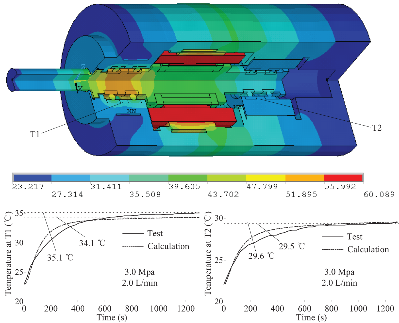
Temperature rise at the outer rings of front and rear bearings at 2.0 L/min, 0.3 MPa and 36,000 r/min.
Figures 12 and 13 show the temperature rise, with different rotational speed, at the outer rings of front and rear bearings at 2.0 L/min and 0.3 MPa, respectively. It is obvious that, with the rising rotational speed, the temperatures increase quickly because of the increasing power loss from bearings and motor. Compared with rear bearing, the temperature at the outer ring of front bearing is higher. When the cooling water flow rate is 2.0 L/min, with increasing oil-air pressure, the lubrication and cooling condition of bearings is better, so the temperature rise decreases. When the oil-air pressure is 0.3 MPa, with increasing cooling water flow rate, the cooling condition of front bearings is better and the temperature rise at their outer rings decreases. However, the cooling condition of rear bearings in that situation has no variation and the temperature rise here has little change.
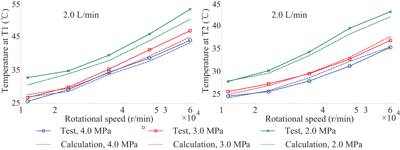
Temperature rise at the outer rings of bearings at 2.0 L/min.
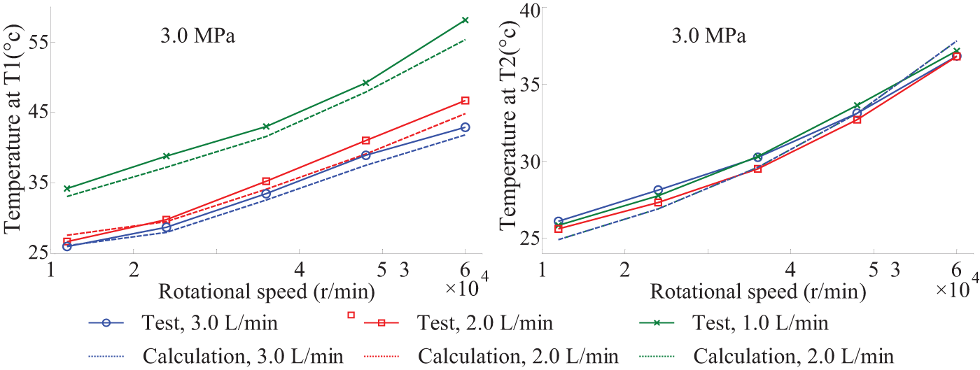
Temperature rise at the outer rings of bearings at 0.3 MPa.
Because of the effect of thermal expansion, the geometrical parameters of bearings are no longer constant and their thermal expansion amounts at 2.0 L/min and 0.3 MPa are shown in Figures 14 and 15, respectively. Due to the change of rotational speed, cooling water flow rate and oil-air pressure, the thermal expansion amounts of bearings’ inner ring, outer ring and ball show the same trend with their temperature rise because of the approximate linear relation of thermal expansion phenomenon as shown in equation (2). The cooling condition at inner rings is worse than that at outer rings, especially at front bearings, so the thermal expansion amounts of inner rings are much larger. The balls have the smallest thermal expansion amounts because of their small basic size.
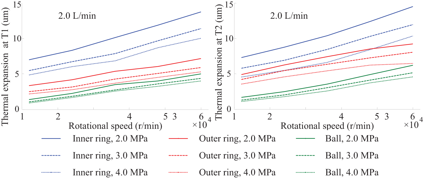
Thermal expansion amounts of bearings at 2.0 L/min.
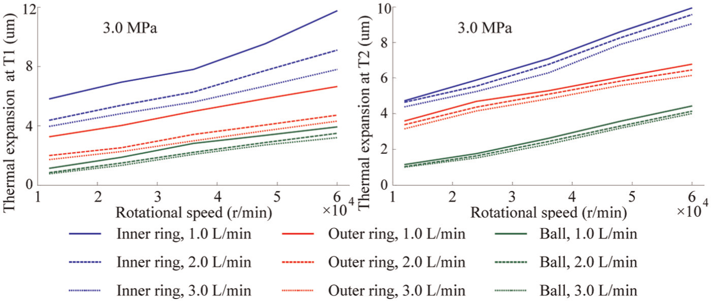
Thermal expansion amounts of bearings at 0.3 MPa.
Analysis for bearing stiffness
Both of the front bearing and rear bearing are analyzed in this article and the bearing stiffness at 2.0 L/min and 0.3 MPa is shown in Figures 16 and 17, respectively. It is obvious that the radial stiffness, axial stiffness and angular stiffness decrease with the rising rotational speed because of the effects of centrifugal force and gyroscopic moment, and this phenomenon was called softening of bearing. 9 At a lower rotational speed, the centrifugal force and gyroscopic moment are very small; hence, the bearing stiffness keeps almost constant. However, when the rotational speed exceeds about 24,000 r/min, the bearing stiffness is gradually softened since the value of centrifugal force and gyroscopic moment increases rapidly. With the decreasing of the cooling water flow rate and oil-air pressure, the contact condition between balls and rings of bearing is closer, which can be obtained from the results of thermal expansion, so the bearing stiffness rises. And the variation domains of rear bearing stiffness, due to the change of the cooling water flow rate, are very small because of their little thermal expansion amount. Compared with the front bearing, the downward trend of rear bearing stiffness is slower.
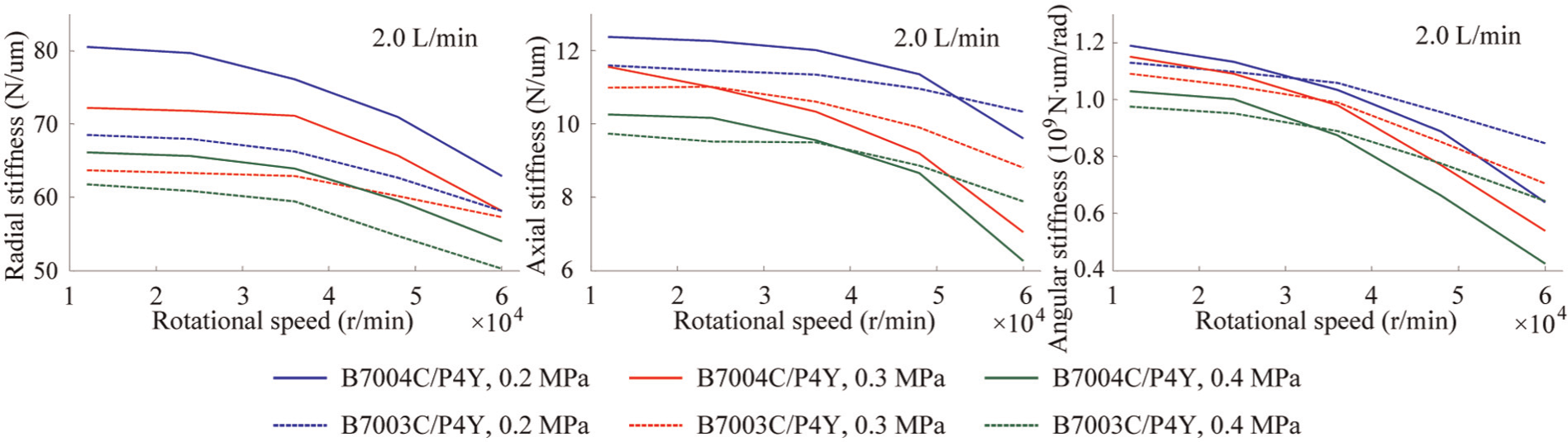
Stiffness of the bearings at 2.0 L/min.
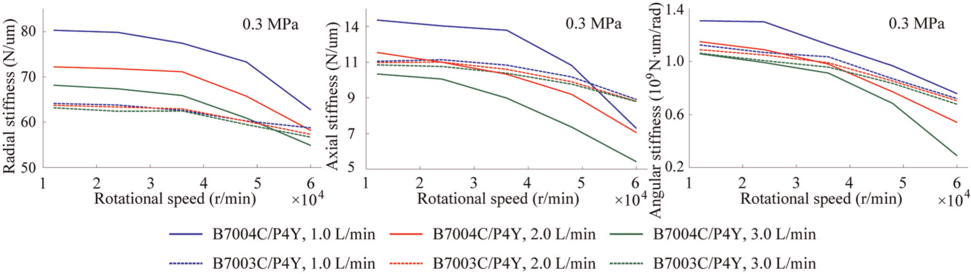
Stiffness of the bearings at 0.3 MPa.
Analysis for spindle stiffness
The spindle stiffness at the test bar tip can be obtained by equation (4), which is shown in Figures 18 and 19, respectively, at 2.0 L/min and 0.3 MPa. With increasing rotational speed, the radial and axial spindle stiffness decrease. And the same downward trend happens when the cooling water flow rate and the oil-air pressure increase. It can be found that the variation trend of spindle stiffness is consistent with the front bearing and its downward trend is more serious. The radial spindle stiffness at the test bar tip is about 50%−60% of the radial stiffness of the front bearing and the axial spindle stiffness totally depends on the front bearing. Figure 20 shows the variation domains of spindle stiffness by the effects of the rotational speed, cooling water flow rate and oil-air pressure. Compared with axial spindle stiffness, the variation domains of radial spindle stiffness are much larger. And it is obvious that the rotational speed has the biggest effect on both of the radial and axial spindle stiffness. The oil-air pressure effect on the radial spindle stiffness is greater than cooling water flow rate, while its effect on axial spindle stiffness has an opposite result.
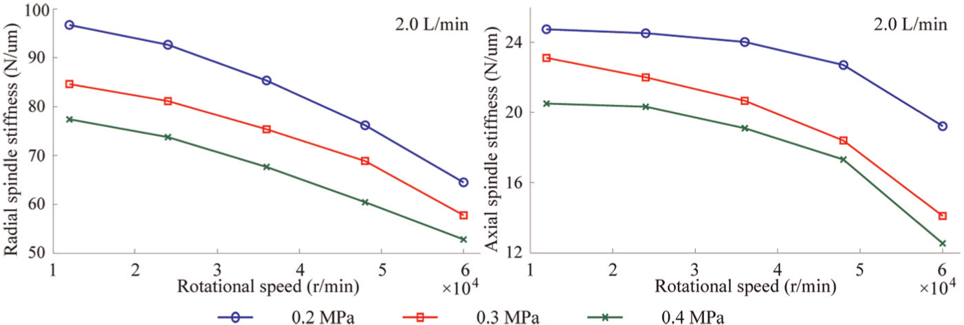
Spindle stiffness at the test bar tip at 2.0 L/min.
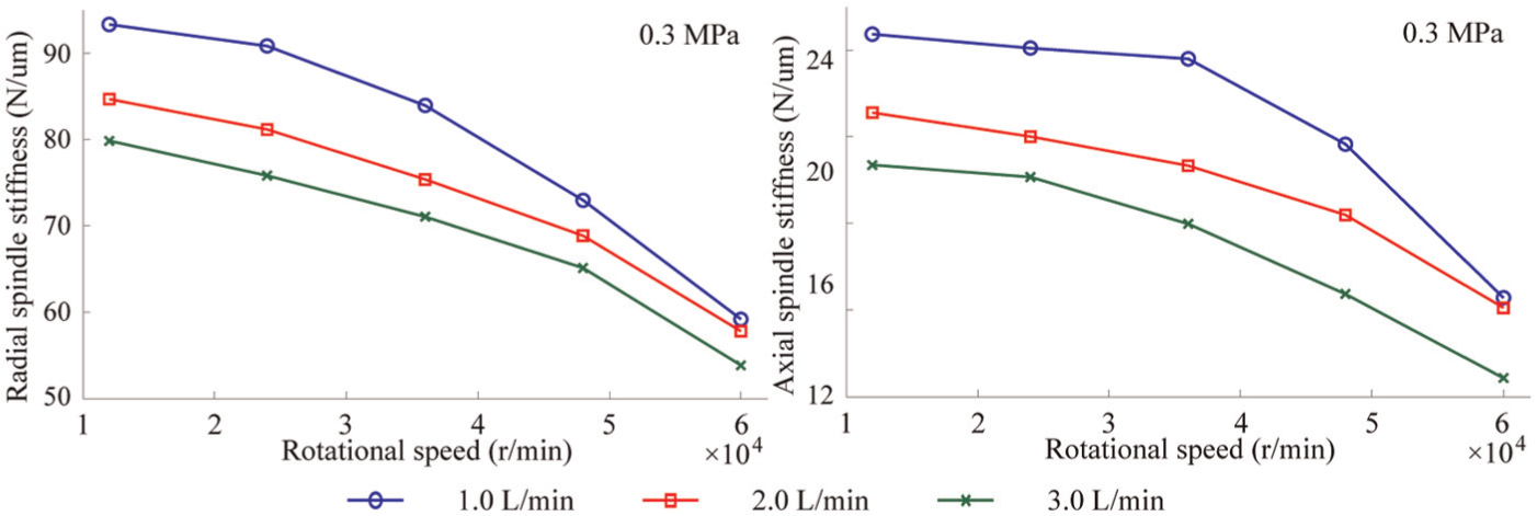
Spindle stiffness at the test bar tip at 0.3 MPa.
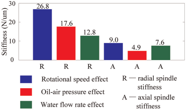
Variation domains of spindle stiffness.
Analysis and validations for natural characteristics
Figure 21 shows the radial vibration displacement spectrum at 2.0 L/min, 0.3 MPa and 36,000 r/min. There are two amplitude peaks at the natural frequencies (1345.8 and 1908.4 Hz) which correspond to the two natural modal shapes of radial vibration. Also, there is an obvious amplitude peak at the rotational frequency (599.2 Hz).
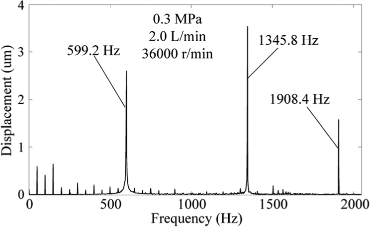
Radial vibration displacement spectrum at 2.0 L/min, 0.3 MPa and 36,000 r/min.
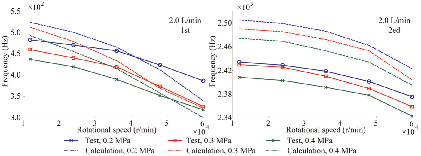
The calculated natural frequency of radial vibration of a high-speed rotor has two branches (forward and backward) affected by the centrifugal force and gyroscopic moment, 8 while in this part only the backward branch is analyzed. Figures 22 and 23 show the natural frequencies of radial vibration at 2.0 L/min and 0.3 MPa, respectively. At a low rotational speed, for example, at 12,000 r/min, the natural frequencies are very close to that at 0 r/min. And the reason is that the system exhibits the same natural modal shapes at those rotational speeds and only the bearing stiffness is a little different. As illustrated, with increasing rotational speed, cooling water flow rate and oil-air pressure, the natural frequencies decrease. And it is not difficult to find that the variation trend is totally consistent with the radial stiffness of the front and rear bearings. Because of the model error, the tested results are a little bigger than the calculated.
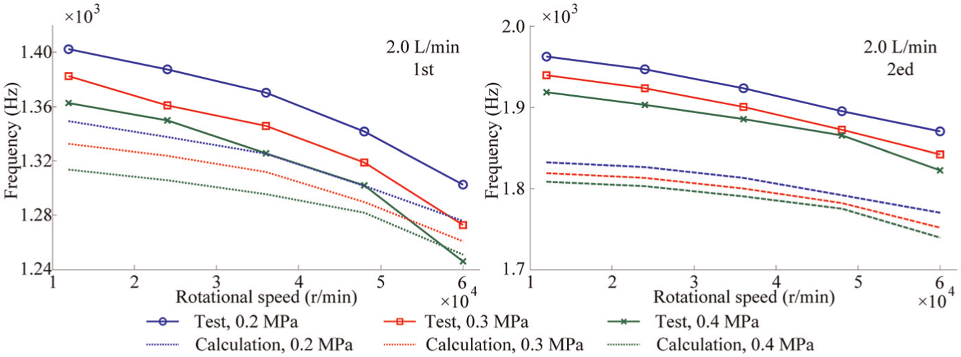
Natural frequencies of radial vibration at 2.0 L/min.
Natural frequencies of radial vibration at 0.3 MPa.
Figure 24 shows the axial vibration displacement spectrum at 2.0 L/min, 0.3 MPa and 36,000 r/min. Like the spectrum in Figure 21, there are also two amplitude peaks at the natural frequencies (433.6 and 2410.3 Hz) which correspond to the two natural modal shapes of axial vibration and an amplitude peak at the rotational frequency (599.2 Hz). Besides, there are two amplitude peaks at 1345.8 and 1908.4 Hz, and they should be caused by the interference of radial vibration signals.
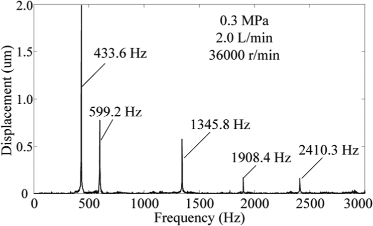
Axial vibration displacement spectrum at 2.0 L/min, 0.3 MPa and 36,000 r/min.
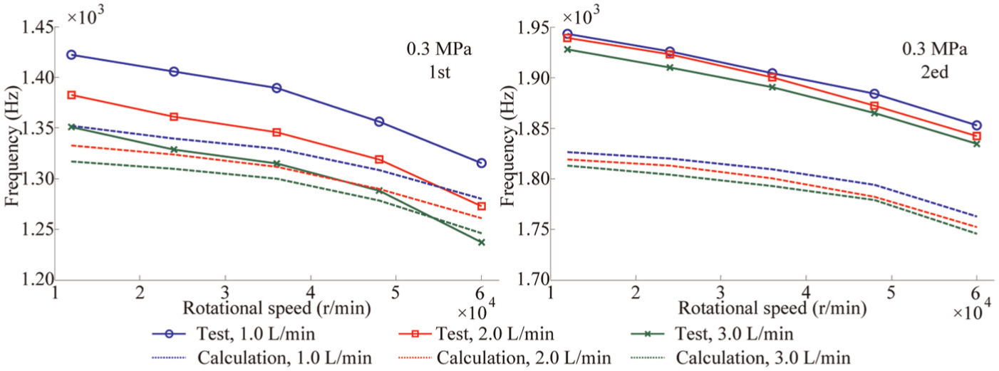
Figures 25 and 26 show the natural frequencies of axial vibration at 2.0 L/min and 0.3 MPa, respectively. Like radial natural frequencies, at a low rotational speed, the axial natural frequencies are also very close to that at 0 r/min, and with increasing rotational speed, cooling water flow rate and oil-air pressure, the variation trend of axial natural frequencies is totally consistent with the axial stiffness of the front and rear bearings. However, the tested results are a little smaller than the calculated which is also caused by the model error.
Natural frequencies of axial vibration at 2.0 L/min.
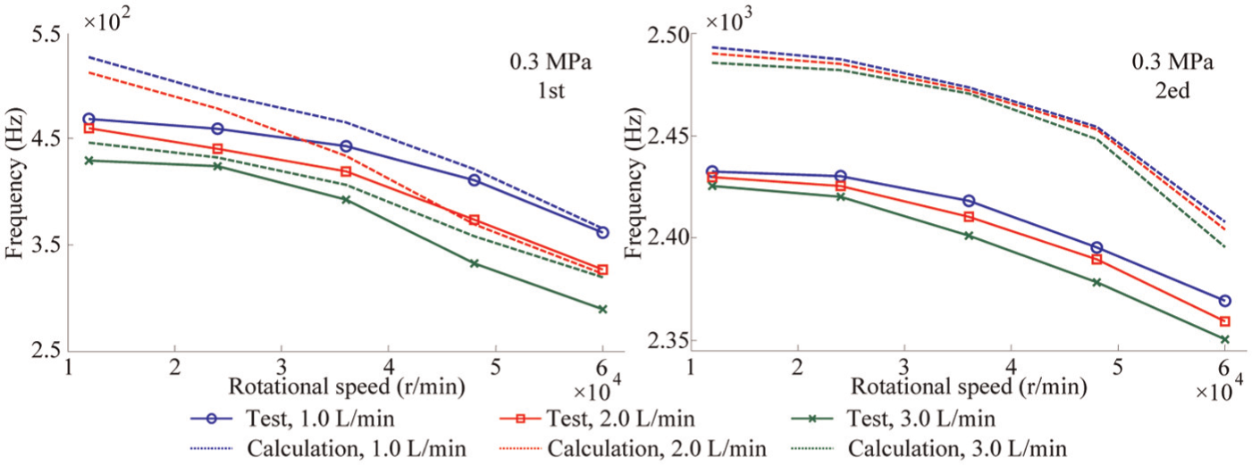
Natural frequencies of axial vibration at 0.3 MPa.
Figure 27 shows the variation domains of natural frequencies by the effects of the rotational speed, cooling water flow rate and oil-air pressure. It is obvious that the rotational speed has the biggest effect on both of the radial and axial natural frequencies. And the effects of cooling water flow rate and oil-air pressure on the variation domain of natural frequencies are at the same level. Compared with that on both of the second radial and axial natural frequencies, the effects of those factors on the first are more significant. Because the cooling water flow rate has little effect on the rear bearing stiffness and the second radial and axial natural modal shapes have a strong relationship with the rear bearing stiffness, the effect of the cooling water flow rate on those natural frequencies is very small.
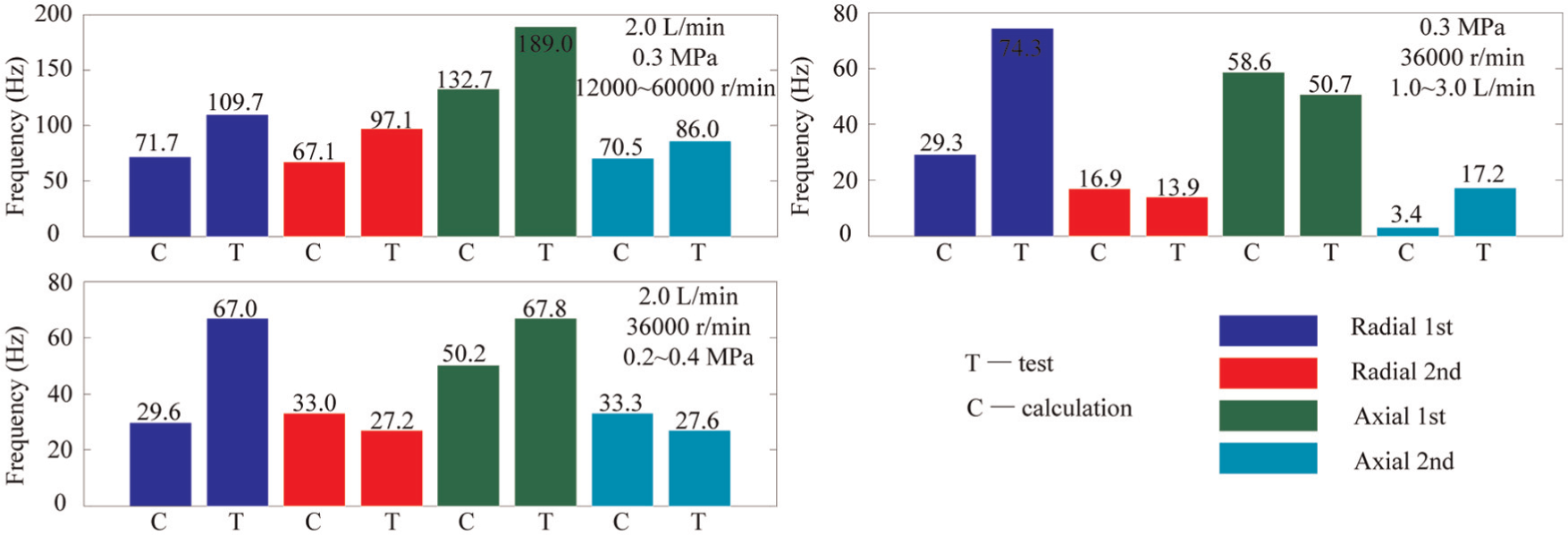
Variation domains of natural frequencies.
Conclusion
A thermal–mechanical coupling model of a motorized spindle is developed for its dynamical properties analysis and validated experimentally under different operating conditions. According to the results, it can be found that the rotational speed, cooling water flow rate and oil-air pressure have a great effect on the temperature rise and thermal expansion of the system. The geometrical parameters of bearings are no longer constant because of the thermal expansion, which can change the bearing stiffness, spindle stiffness which mostly depends on the bearing stiffness, spindle natural frequencies and so on. And increasing thermal expansion makes the spindle stiffness and natural frequencies to increase, which is good for the dynamical properties of the system. While, it brings more bearing heat generation and makes a higher temperature rise. Thus, choosing a perfect cooling condition should consider the two contradictory factors and their target is to get an integrated optimal system performance. The bearing preload, with an axial movable rear bearing pedestal, will not be influenced by the thermally induced preload. So there is no need to consider the rotational speed and cooling condition when designing the bearing preload force for the spring-preload situation. However, in the system with a fixed bearing pedestal, the axial thermal expansion of the shaft complicates the geometric relationship of bearings more seriously, and this situation needs more in-depth study in the choice of rotational speed range and cooling condition to reduce the effect of the thermally induced preload. The rotational speed and cooling condition have a small effect on the natural modal shapes of the system.
Footnotes
Appendix 1
Declaration of conflicting interests
The authors declare that there is no conflict of interest.
Funding
This project is supported by the National Natural Science Foundation of China (Grant No. 51475054).