
Abstract
This article considers the turning characteristics of robotic fish with two-degree-of-freedom pectoral fins and flexible body/caudal fin. The hydrodynamics are first established for three cases propelled by both sides of pectoral fins, flexible body/caudal fin, and composite of them. Then, the turning characteristics of such three cases are analyzed by numerical simulations and experiments. The results show that if robotic fish is cooperatively propelled by pectoral fins and flexible body, it can obtain the fast turning speed and the average turning speed is up to 0.6 rad s−1. The smallest turning speed is achieved as robotic fish is only propelled by pectoral fins; however, it can turn on the spot in this case. The presented results provide the more abundant ways of turning, the better maneuverability, and the higher turning speed for the proposed robotic fish.
Keywords
Introduction
The biomimetic robotic fish has been widely investigated in literature for many years. The early works mainly focused on the body and caudal fin (BCF) mode. 1 Since the median and/or paired fin (MPF) mode has advantage over BCF mode in maneuverability and stability, three categories of robotic fish propelled by MPF mode have been developed, namely, multi-fin oscillating, pectoral-fin flapping or/and gliding, and long-fin undulating. 2 –10 Nanyang Technological University developed a four-fin propulsion bionic prototype based on modular design, which has high efficiency and maneuverability. 3 Peking University developed a biomimetic turtle with four flapping fins, which could achieve complex three-dimensional movement including the pitch, heave, yaw, dive, and roll. 4 Beihang University developed a biomimetic turtle with five degrees of freedom (DOFs), which could turn flexible on the spot, achieve 1 m s−1 forward speed, and dive up to 30 m. 5 Kato developed the first mechanical pectoral fin-driven bionic robotic fish, which took the black bass as the prototype. 6 –8 The Chinese Academy of Sciences developed a robotic fish with two pectoral fins and four-joint flexible body, which could turn with 72° s−1. Meanwhile, its turning radius was up to 0.38 times of body length. 9 Again, they developed a biomimetic Esox lucius with two-DOF pectoral fins and multi-joint flexible body, which could achieve fast turn with 120° s−1. 10
Inspired by the above works, two prototypes of biomimetic robotic fish were designed by the authors. 11 –13 Especially for the proposed robotic fish in the study by Li et al., 13 its pectoral fins can move forward and backward, rotate around the axis of pectoral fin, and achieve the composite motion of them. Meanwhile, it can be cooperatively driven by the two-DOF pectoral fins and three-joint flexible body together. Pectoral fins with two DOFs provide the robotic fish more maneuverability. For example, there are at least six ways for robotic fish to achieve straight swimming. 13 Since the turning behavior is more important for fish to adapt to the environment and evade predators, this article mainly considers the turning characteristics of robotic fish. First, the hydrodynamic models are established for pectoral fins and flexible BCF, and then the turning mechanism is analyzed by numerical simulation and experiments. As a result, three turning ways are summarized, which improves the maneuverability and environmental adaptability of the robotic fish.
Kinematic modeling of robotic fish
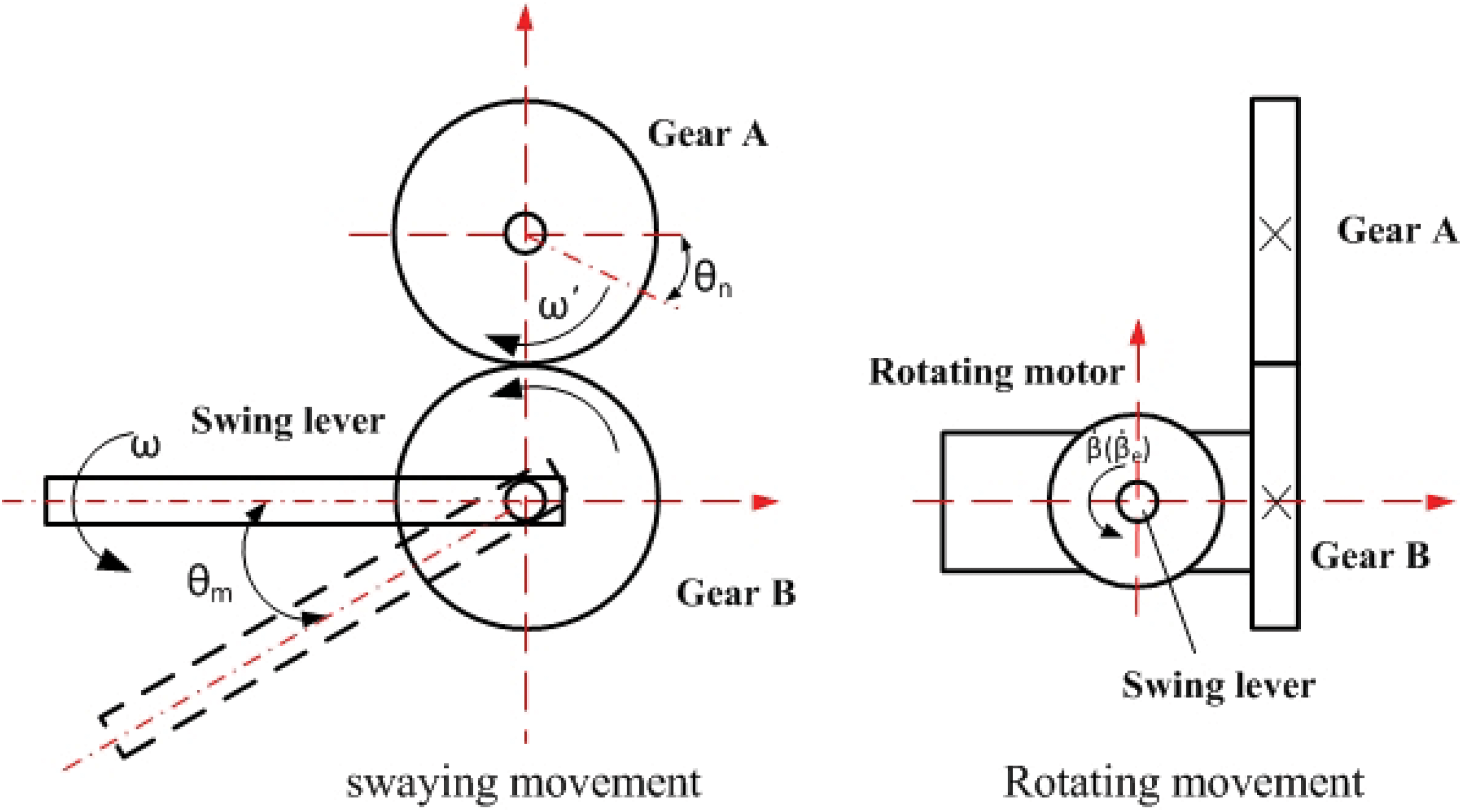
The prototype of robotic fish is shown in Figure 1 and its propulsion mechanism is given in Figure 2. It is clearly shown that the pectoral fins are symmetrically arranged on both sides of robotic fish and the flexible body is made up of three rigid joints and a caudal fin. As shown in Figure 2, the rotating motors directly drive the pectoral fins to do oscillating rotary motion, and the swaying motors actuate the pectoral fins to move forward and backward by gear transmission. Since the rotating motor is fixed on the parts driven by swaying motors, the rotation and sway of pectoral fins are independent and thus the composite movement of them can also be achieved. The flexible body is made up of three rigid joints and the caudal fin is a passive part. In practice, the skin of flexible body is made up of rubber, and the shell of the rigid head is designed based on the streamlined appearance of codfish and made by PLA fiber. The rays and skin of pectoral fins are made by flexible carbon rods and heat-shrinkable plastic material, respectively. The technical parameters of robotic fish are shown in Table 1.

Prototype of the proposed robotic fish.

Overall propulsion mechanism of the biomimetic fish.
Technical parameters of the robotic fish.

CPU: Central Processing Unit; PLA: Poly Lactic Acide.
In what follows, the movement laws are given for pectoral fins. Let {X,Y,Z} and {x,y,z} denote global and local coordinate systems, respectively, U be the direction of swimming, ω be the swaying angular speed, θm be the backward swaying angle, θn be the steering angle of servomotor, and
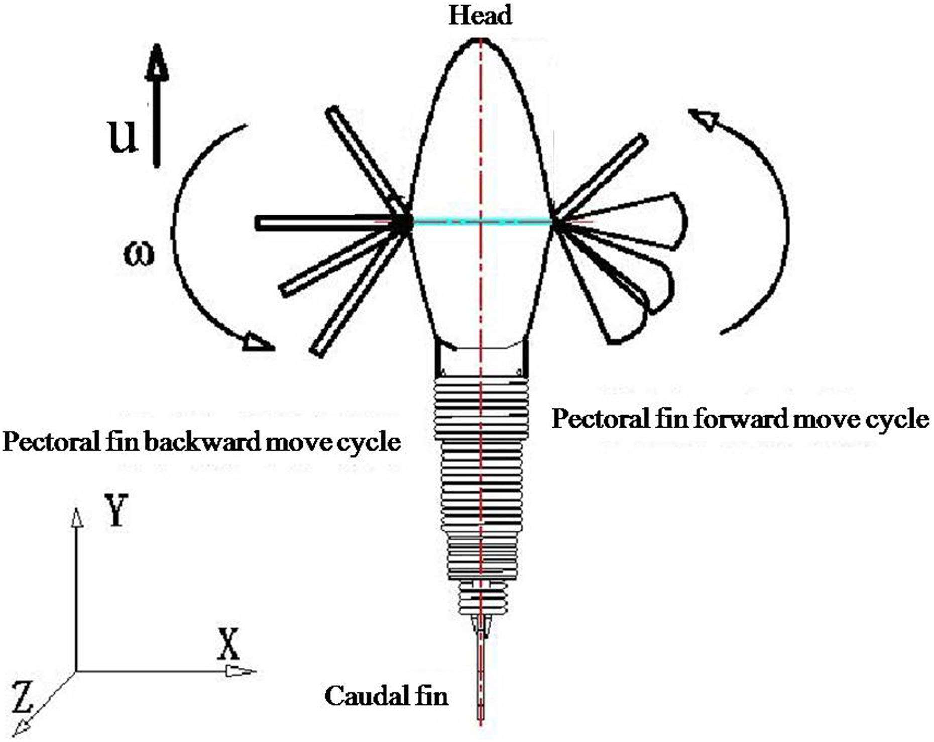
Diagram of the backward and forward movements for pectoral fins.
Motion diagram of mechanism for pectoral fins.
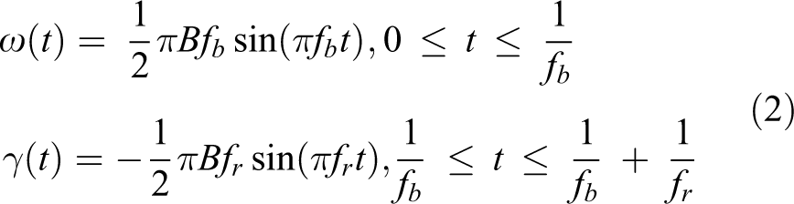
During the turning, the motion of each pectoral fin is divided into four periods as shown in Figure 5, in which ω, ωn, γ, and ωn1 denote the frequency of each period, α is the attack angle, βn and βl, respectively, denote the rotating angle of the first and second rotations, and θl = θn is the forward swaying angle. Let B denote the amplitude, θ0 be the original angle of back stroke, and fb and fr are the frequencies of the backward and forward swaying, respectively. Then, the laws of movement for pectoral fins are defined as follows Diagram of the movement for pectoral fins.

From equation (1), the angular speed of the backward and forward swaying can be derived as
Now, the motion laws of flexible BCF are considered. Generally, the flexible body results in turning by fitting with the Lighthill curve as follows 1,3,5,9,14,15

where h(xn,t) is the offset of each point to the centerline of the body, hT is the swaying amplitude of flexible body in the horizontal plane,

where i represents discrete time, h(xn, i) is the position of flexible body at time i, M represents the discrete resolution, and hT has the same meaning as in equation (3).
The junction of rigid head and flexible body is at the point o, which is also the original point of local coordinate, just as shown in Figure 6. In this figure, ϕ is the swaying angle between rigid head and the centerline of flexible body, H and P are the centroids of rigid head and flexible body, respectively. Then, the kinematics of ϕ can be given as follows
14,18
–20
Diagram of turning for body/caudal fin.

where
Hydrodynamic analysis of turning
In this section, the left turning is taken as an example to analyze the hydrodynamics of turning. Following the same line, the results about the right turning can be obtained and thus omitted here. In what follows, three cases are discussed.
Case 1: Turning propelled by pectoral fins
In this case, the force condition of robotic fish is shown in Figure 7, where
Force analysis of pectoral fins in turning.
As shown in Figure 7, the movement of pectoral fin can be divided into two periods as the robotic fish turns left. In the first period, the right moves backwards and the left moves forward; meanwhile, both of them are perpendicular to the horizontal plane. In the second period, both of the pectoral fins are returned from the horizontal plane to the initial position in which the resistance is small and thus can be negligible. Then, by equations (1) and (2), the motion laws of right pectoral fin are derived as follows

where θmrp and θlrp, respectively, denote the swaying angle as the right pectoral fin strokes backward and forward, θro0 is the original angle of right pectoral fin moving backward, and Brp denotes the swaying amplitude. The frequencies of moving backward and forward are frpb and frpr, respectively. By taking the derivatives with respect to t, equation (6) becomes

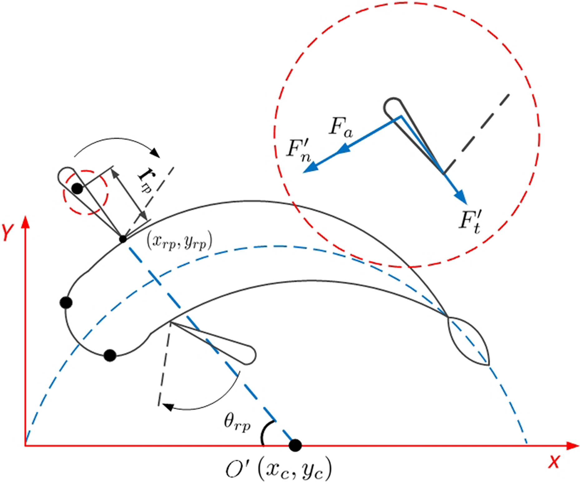
where ωrp and γrp are the corresponding angular speeds. Hereinafter, we analyze the force and torque generated by right pectoral fin by employing the elemental integration method. Specifically, the fan-shaped pectoral fin is divided into several slices of microelements along the direction of the expansion, and then, the force and torque of each microelement are analyzed. Finally, the force and torque of the whole pectoral fin are obtained by integrating along the direction of expansion just as shown in Figure 8, where
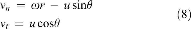
Let v be the vector sum of vn and vt and α be the attack angle, then

Again, the normal force dFn and the spanwise force dFs exerted by the surrounding fluid on microelement P are 21,22

where ρ is the fluid density, dA is the area of microelement P, Cn is the lift coefficient, which depends on attack angle α, and Cd is the fractional drag coefficient and its value varies with Reynolds number Re. Let μ be fluid viscous coefficient, δ be the angle of spread of fan-shaped pectoral fin, and R be the diameter of pectoral fin, then

Integrating the force of microelement P along with the spread direction of fins, the total normal force

In addition, the fluid additional mass force dma is exerted on microelement P as right pectoral fin moves backward. According to the study by Kato and Furushima 6 and Blake, 21 dma is as follows

where c = δ ⋅ r is the chord length of the slice and l = dr is the slice length. Further, the force dFa produced by dma can be obtained as follows 6,23

By integrating the force dFa along with the spread direction of fins

Then, as shown in Figure 8, the rotational torque Tr of right pectoral fin in the first period can be derived as follows
Force analysis of infinitesimal slice for pectoral fin.

Integrating dTr along with the spread direction of fins, the left rotational torque produced by the right pectoral fin as it moves to the backward is

Similarly, the rotational torque Tl of the left pectoral fin is

Combined with equations (16) and (17), the total rotational torque Ml produced by two pectoral fins is

Case 2: Turning dynamics of flexible BCF
In this case, the fluid resistance is analyzed first as follows 24
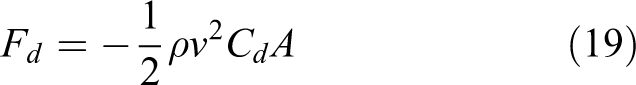
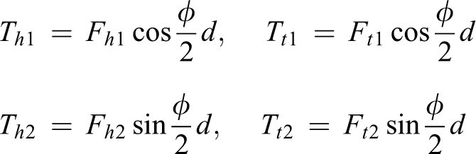
where Fd is the resistance of robotic fish, ρ is the fluid density, v is the velocity of robotic fish compared to the fluid, Cd is the resistance coefficient, and A is the area of the projection of robotic fish on a plane perpendicular to the direction of motion. The force conditions of this case are given in Figure 9, in which Fh1 and Fh2 are the lateral resistance and forward resistance exerted on the rigid head, respectively, Ft1 and Ft2 are the lateral resistance and forward resistance exerted on the flexible BCF, respectively, and C and E are the instantaneous centroid of rigid head and tail during turning, respectively. Under the assumption that the centroid and the buoyant center of robotic fish are all located on the Z-axis, these parameters are formulated as follows
16
Force analysis of body/caudal fin in turning.

where Ah1 and Ah2 are the areas of the side and the front of rigid head immersed in water, respectively; At2 and At2 are the areas of the side and the front of flexible BCF immersed in water, respectively; and kh1, kh2, kt1, and kt2 are the resistance coefficients associated with the swing frequencies fk1, fk2, ft1, and ft2, respectively. Assuming that ΔCHP is always isosceles triangle during turning, that is, the body of robotic fish always rotates around the whole center of gravity, it is easy to verify the following

Assuming

with
where M2 is the total rotational torque coordinately produced by flexible BCF.
Case 3: Turning dynamics of coordinated propulsion by pectoral fins and flexible body together
In this case, the coordinated propulsion force and torque of turning can be obtained by combining with case 1 and case 2. Obviously, the total centripetal force F1 produced by pectoral fins is
And the total centripetal force F2 produced by flexible body/caudal fin is
Then, the total centripetal force Fn exerted on the whole robotic fish is

Generally, the centripetal force has the form

where Rs and ωs are turning radius and angular velocity, respectively. Combined with equations (18) and (21), the turning radius is

Combined with the above, the hydrodynamic model of robotic fish is as follows

where Ms and I are the total torque and the moment of inertia of the whole robotic fish, respectively.
Turning characteristics analysis
Based on equations (18), (21), and (27), this section analyzes the turning characteristics of robotic fish by numerical simulation. The initial values of motion parameters are given as
For case 1, the result of simulation is shown in Figure 10. It is noted that the flexible BCF bend as a C-type and keep static when the robotic fish turns. As shown in Figure 10, the robotic fish could achieve turning smoothly, and the average angular speed of turning is 0.5 rad s−1.

Turning angular velocity propelled by pectoral fins.
For case 2, the result of simulation is shown in Figure 11. As shown in Figure 11, both sides of pectoral fins keep parallel to the horizontal plane and are always inactive. The turning of robotic fish is also smooth and the average angular speed of turning is 0.4 rad s−1, which is less than that of case 1.

Turning angular velocity propelled by body/caudal fin.
For case 3, the result of simulation is shown in Figure 12. The sum of the swaying frequencies fb and fr is equal to the C-type swaying frequency f. As shown in Figure 12, the turning of robotic fish is also smooth and the average angular speed of turning is 0.6 rad s−1, which is larger than those of case 1 and case 2.
Turning angular velocity of pectoral fins and body/caudal fin.
Experiment
Experiments of robotic fish are carried out in an indoor swimming pool with 2 m × 3 m × 0.4 m. The information within the swimming tank is captured by an overhead CCD camera. The image is transmitted to a personal computer and processed by a visual tracking software platform developed to obtain the position and orientation of robotic fish in real time and the sampling period is 0.5 s. The two-dimensional trajectory of robotic fish can also be extracted and recorded for offline analysis. The motion laws of robotic fish are determined by equations (1), (2), and (5). The initial values of parameters are just the same as the numerical simulation. Figure 13 shows a photograph of the experimental environment.
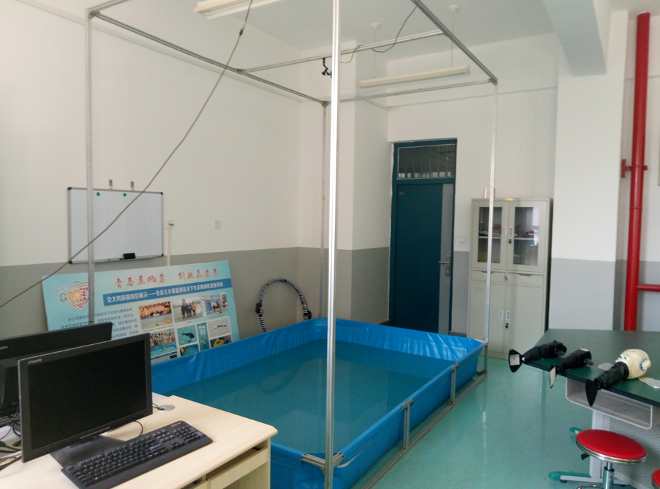
Experimental environment of robotic fish.
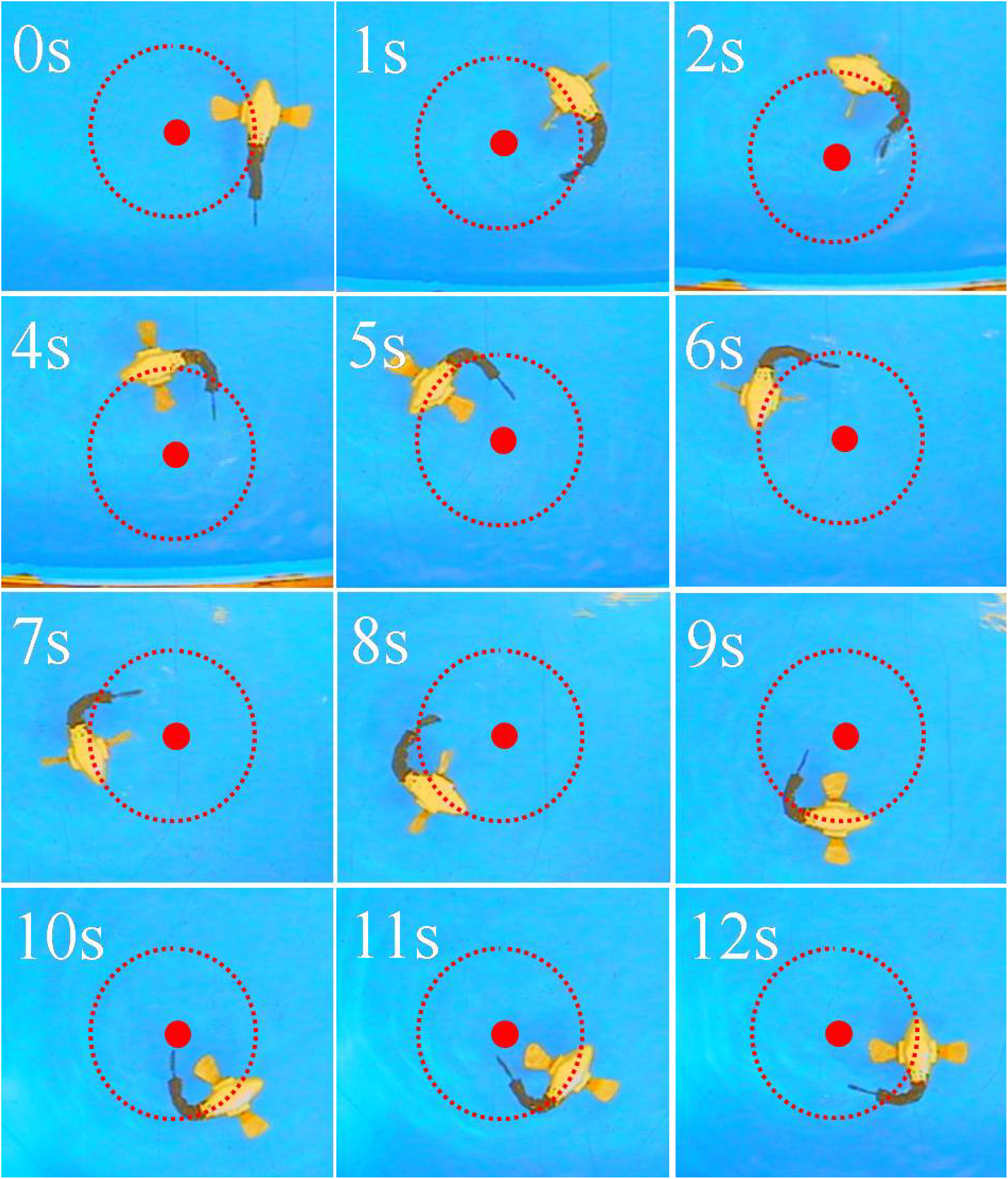
For case 1, the results of experiment are shown in Figures 14 and 15. As the Figure 15 shows, the angular speed changed periodically between 0.34 rad s−1 and 0.44 rad s−1 and its average is about 0.4 rad s−1. Compared with the simulation results in Figure 10, the angular speed is slightly slower than 0.5 rad s−1, but more stable than 0.35–0.66 rad s−1. In addition, the turning radius is about 0.15 m, nearly turning on the spot.

Turning experiment for bilateral pectoral fins.

Turning experiment result for bilateral pectoral fins.
For case 2, the results of experiment are shown in Figures 16 and 17. As the results in Figure 17 show, the angular speed changed periodically between 0.38 rad s−1 and 0.64 rad s−1 and its average is nearly 0.5 rad s−1. As a comparison, the average angular speed is larger than the results in Figures 11 and 15. On the other hand, the stability of turning gets worse than that in case 1.

Turning experiment for body/caudal fins.

Turning experiment result for body/caudal fins.
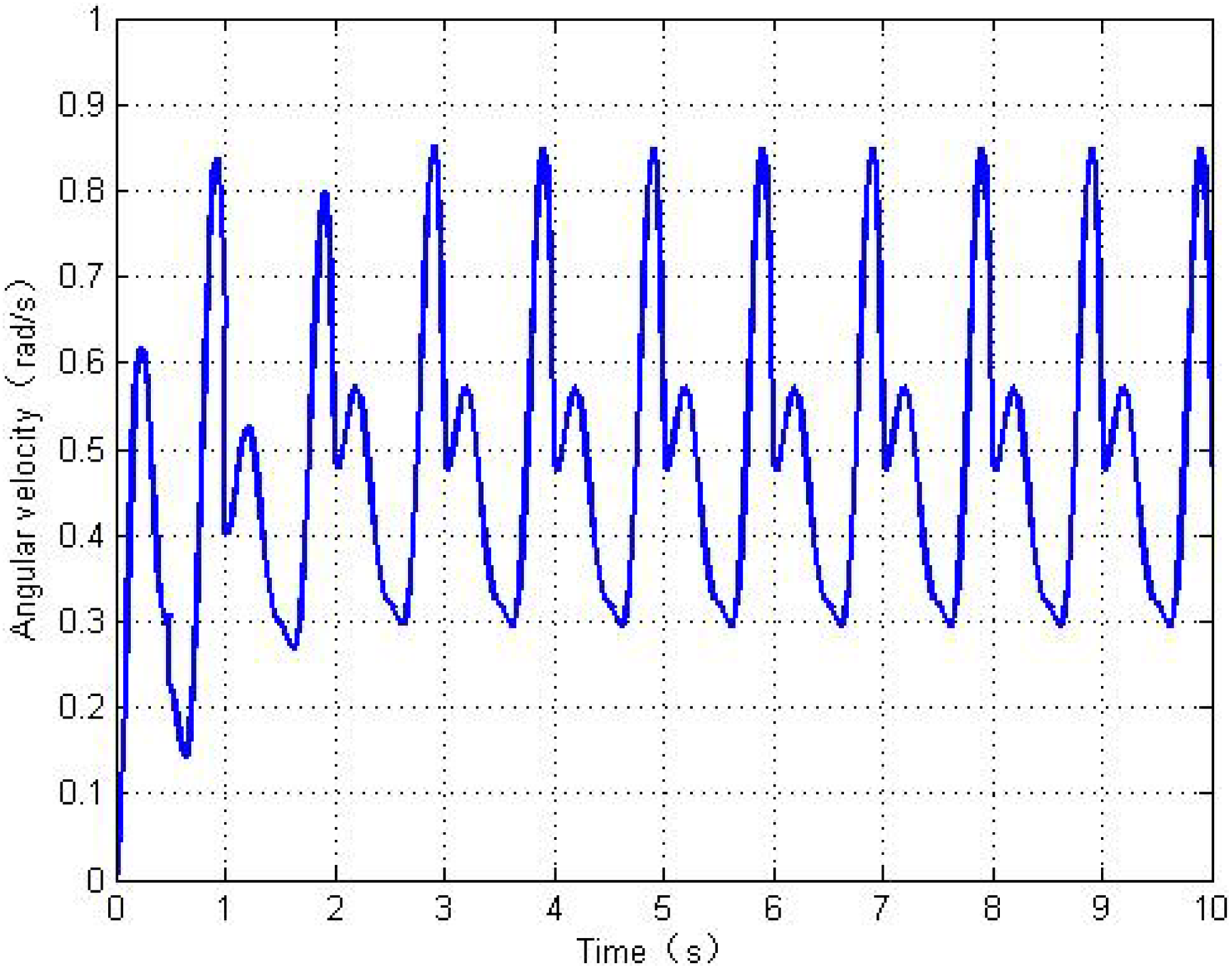
For case 3, the results of experiment are shown in Figures 18 and 19. As the results in Figure 19 show, the average angular speed is about 0.57 rad s−1, the range of the angular speed is 0.3–0.78 rad s−1. Obviously, the angular speed is larger than those in the above two cases and is consistent with the results of numerical simulation in Figure 12.
Turning experiment for pectoral fins and body/caudal fin.

Turning experiment result for pectoral fins and body/caudal fin.
Conclusion
This article investigates the turning characteristics of robotic fish proposed by Li et al., 13 which consists of two-DOF pectoral fins and flexible body/caudal fin. Based on the hydrodynamic models of pectoral fins and flexible body/caudal fin, three turning ways are proposed. The results of numerical simulations and experiments show that the fast turning speed is achieved as the robotic fish is cooperatively propelled by pectoral fins and flexible body/caudal fin. As robotic fish is propelled only by pectoral fins, it can turn on the spot steadily but its angular speed is the smallest. In future works, the turning characteristics of such a robotic fish will be further investigated by employing the fluid analysis and central pattern generator control method.
Footnotes
Acknowledgements
The authors would like to thank the associate editor Prof. Hai Huang and anonymous reviewers for theirs valuable advice and help.
Declaration of conflicting interests
The author(s) declared no potential conflicts of interest with respect to the research, authorship, and/or publication of this article.
Funding
The author(s) disclosed receipt of the following financial support for the research, authorship, and/or publication of this article: This work was supported by the Natural Science Foundation of China (NSFC) under grant 61663020.