
Abstract
Biomimetic robots can potentially perform better than conventional robots in underwater vehicle designing. This paper describes the design of the propulsion system and depth control of a robotic fish. In this study, inspired by knife fish, we have designed and implemented an undulating fin to produce propulsive force. This undulating fin is a segmental anal fin that produces sinusoidal wave to propel the robot. The relationship between the individual fin segment and phase angles with the overall fin trajectory has also been discussed. This propulsive force can be adjusted and directed for fish robot manoeuvre by a mechanical system with two servomotors. These servomotors regulate the direction and depth of swimming. A wireless remote control system is designed to adjust the servomotors which enables us to control revolution, speed and phase differences of neighbor servomotors of fins. Finally, Field trials are conducted in an outdoor pool to demonstrate the relationship between robotic fish speed and fin parameters like phase difference, the number of phase and undulatory amplitude.
Introduction
Marine life is one of the main areas at which man's interference wrecked natural destruction. This fact steers us to design equipment with much more adaptability to nature. To attain such a goal, introduction of foundamental changes in design of the present equipment will be inevitable. Investigating the biomimetic fish-like robots is an obvious example for the goal. Diagram depicted in Fig. 1, shows the procedure of producing biomimetic devices.

Procedure of producing biomimetic devices [1].
Propellers are extremely destructive tools are used in the most recent water vehicles. The broadband noise from the propellers of any motorized vessel may have severe acoustic effects on marine wildlife, including changes of behaviour, ‘masking’ of other signals spread by fish and temporary or permanent hearing trauma [2].
Scientists make attempts to combine biology and engineering to improve existing robots. Vast number of marine creatures produces propulsion by sinusoidal waves. Many of them produce the waves by means of median and/or paired fin, MPF. This naturally selected swimming mechanism can potentially provide propulsion required for manoeuvre [1, 3–5].
In this study, we will investigate the sinusoidal wave production method by means of fins which imitate MPF fish. In the robotic fish investigated in this paper, sinusoidal wave will be produced by six servomotors located in fish-like robot's fin. A mechanical system, including two servomotors, serves to control direction and depth of the robotic fish movement. we will discuss in detail wireless control system, designed for fish robot control,. Changes in speed, direction of crank rotation and phase differences of adjacent servomotors in the fin will be controlled by the control system. By this method, swimming direction and speed of fish robot can be changed from out of pool.
In section 6, we will study experimental phenomena and effects of physical parameters of the fish robot on its velocity. Finally, in section 7, we will develop some ideas about working on biomimetic underwater devices and fish robots.
Natural MPF Fish
As shown in Fig. 2, wave producing fins in MPF fish are located in several parts of their body. Shape and location of wave producing fins in these fish are in such order that some of these fins are just used for producing wave and others are used for producing oscillation and wave.

MPF fish with undulatory and oscillatory fin motion [3].
Producing oscillation in the fins of the robotic fish causes severe oscillation in movement of the robot. Due to this fact, we just investigate the wave producing fins (Fig. 3) and an attempt will be made to minimize oscillation in robotic fish movements.

Till now, some related works have covered kinematics modelling, mechanical designs, prototype implementation and experiments [9–18]. In Fig. 4, examples of imitator robotic fish and associated natural fish and their manufacturer's name are shown.
Forces required for robotic fish's movement in Fig. 4 are provided by producing sinusoidal waves by means of fins. In a design inspired by knife fish, a single force under robot's body is produced, but in a design inspired by Stingray, the forces are produced as two distinctive forces at robot's sides.

Control and manoeuvre of the robotic fish inspired by knife fish is much easier due to control of just one force direction,. Density control and equilibrium in swimming are accomplished by means of a buoyancy tank located in upper part of the robot [2, 6, 18, 23, 24].
Design of a mechanical model of the fish robot
Here, the investigated design is similar to those by Low [2, 6, 24, 25] and Willy [8]. Our design has 6 servomotors to produce sinusoidal wave as shown in Fig. 5a and b. The application of a mechanical system consisting of two separated servomotors for depth and direction control is unique to our design.

Servomotors of fins with phase differences between adjacent cranks.

Schematic model of fish robot
Each crank can rotate and change the longitudinal direction of the robot body from −90° to +90°. The amount of this rotation for all servomotors is the same and can be adjusted by operator. The phase differences between two adjacent cranks are the same, changing from 10° to 120°. To change direction and swimming depth, a mechanical system consisting of two separate servomotors is designed. For right and left movement, the fin should rotate in horizontal plane by direction control servomotor, and for depth change, it should rotate in vertical plane. Therefore, fish robot will be able to swim and manoeuvre all over the pool.
Fig. 6 shows the mechanism of wave-producing fin which uses 6 servomotors. In this mechanism fin ray connected to n th motor makes an angle with the robotic fish axis which is denoted by θ n . By changing in the range of this angle using controller, magnitude of sinusoidal wave changes.
At any moment, θ
n
is calculated by Eq. (1), [6]


Discrete model of sinusoidal wave developed by cranks and membrane.
where:
A: amplitude of sinusoidal movement of fin
R: radius of the crank
v: phase difference between two servomotors
t: time
n: servomotor number
β: angle of the cranks measured from reference line
We can create the favorite number of sinusoidal wave (N) in the fin which is related to phase difference (β) and the number of fin segments (n
f
) by:


N: the number of servomotors in the fin.
As seen in Fig. 7a, b, distance between two fin rays at adjacent servomotors varies during wave movement, being between Smin and Smax These two symbols denote minimum and maximum lengths of the fin membrane, and are calculated by Eqs. (3) and (4), respectively.

(a) minimum, (b) maximum length of the fin membrane.


where,
X: The maximum angle difference between two adjacent cranks.
For fish robot manoeuvre a propulsive force with capability of changing direction is needed. We can use different designs to decrease robot density [6, 15, 21]. In this study, we have decided to use a density decreasing vest. For forward movement, the robot fin should exert a force to fluid in rear direction and to dominate to resultant gravitational and buoyancy forces, it should exert a force to fluid in downward direction. Robot density should be more than fluid density even by density decreasing vest.
The forces are shown in Fig. 8 for forward movement.
For upside movement, this force direction should be near the FN and for downward movement, this force direction should be near the FR. Also, for right and left movements, this force should be applied in horizontal plane and for depth change, it should be applied in vertical plane. among other properties of the robotic fish is the ability to combine these movements. with increase in the number of fins, analysis of forces becomes more difficult [23].

Produced forces by the fin of fish robot and their resultant [3].
Until now, several works have been dedicated to the examination of robot control system[2, 21, 22]. The control system presented in this paper controls undulating fin and pectoral fin of the fish robot by the special methods [9, 21, 22]. The control system presented in this study consists of two parts including the installed control board on fish robot and the control handle (Fig. 9). A control board is used to control handle of the robot. The program used to control the application, shown in Fig. 10, is saved in a micro-controller. Program instruction in the micro-controller is displayed in LCD and this program has the capability to control and change some parameters using control handle keys. Then, the instruction signals are amplified by radio transceiver and transmitted by control handle antenna to the board antenna installed on the fish robot. The control handle board circuit is shown in Fig. 11.

The components of control system of the fish robot (Voltages: Circuits 3.3V, LCD & motors 5V).

Employed RXQ2 Radio Transceiver control process on fish robot's control handle board.

Circuit of the control handle.
In control board installed on the robot, two AT meg16 micro-controller have been imbedded (Fig. 12). The first micro-controller controls direction and depth changer servomotors and the second, controls fin servomotors. Transmitted data from control handle is sent to the fish robot antenna and transmitted to RXQ2 radio transceiver installed on control board. Then, the control data delivered to the first micro-controller to control depth and direction control servomotors. This micro-controller, after processing data, delivers parts of the processed data to the second micro-controller in order to control fin servomotors. Detailed board circuits installed on the fish robot, are shown in Fig. 13. Investigations on this method of wave production by robotic fish show that increasing phase difference in a permissible range, which through Eq. (2) leads to increased number of waves in fin, reduces undesirable rotations around coordinate axes. similarly, by increase in phase difference, little change in velocity will be resulted in the robotic fish movement and experiments will be done more accurately.
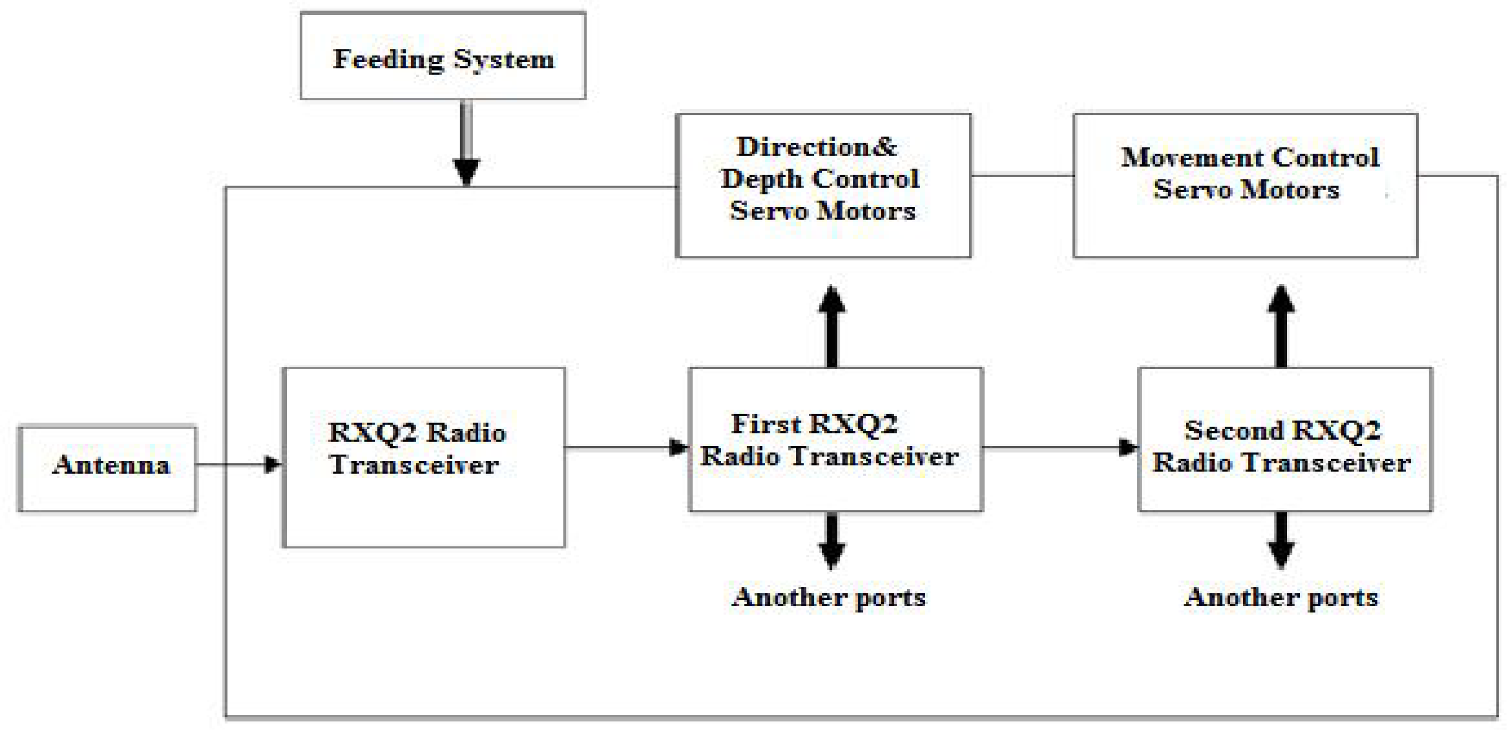
Servomotors’ control process and employed RXQ2 Radio Transceiver on the control board of fish robot.

Fish robot's control board circuit
The velocity of the fish robot, v, is measured experimentally for various phase differences between two adjacent servomotors, β, and servomotor frequencies, v. In this study, the phase difference is constant through the fin. The experimental results are shown in Fig. 14. It is observed that the velocity of the fish is increased as we increase the servomotor frequency.

Experimental velocity graph for various phase difference and servomotor frequencies.
It is observed that the maximum speed always occurs between phase 60 and 70.
According to Eq. (2), we can redraw the graphs in Fig. 13 to show the relationship between velocity and the number of waves, N, in undulating fin. In Fig. 15, the graph is shown for various servomotor frequencies.

Experimental velocity graph for various numbers of waves and servomotor frequencies.
We find that the maximum speed always occurs between 0.8 and 1 wave.
In other experiments, the velocity of the fish robot was measured for different amplitudes of the cranks, different magnitudes of θ max , and servomotor frequencies for β = 60°. The experimental results are shown in Fig. 16.

Experimental velocity graph for various undulatory amplitude and servomotor frequencies for β = 60°.
It is also observed that the maximum speed always occurs between undulating amplitude 44° and 46°.
In this work, we noted the necessity of imitation from nature to develop new products for human beings’ welfare. We also noted some examples of nature inspiration to produce biomimetic equipment. Similarly, by inspiration of MPF fish especially knife fish, we presented the mechanism of single anal fin robotic fish with 6 servomotors. Also, a mechanical system with two separate servomotors was used to control direction and depth of swimming.
Due to the modular and configurable features, the designed robotic fish and the fin mechanisms can be easily modified to model fish robots with different fin attachments and layouts.
Finally, wireless remote control system for the robot was designed and produced. The system was capable of controlling robotic fish from out of the pool and up to 150 meters distance.
The underwater vehicles model given here was non-minimum phase. An indirect adaptive control system was designed for the depth control using the anal fins. The control system presented in this study consisted of two parts which involved the installed control board on fish robot and the control handle.
Despite the small amount of quantitative experimental data collected, the observations made and results obtained in the experiments encourage and inspire us to proceed further in investigating factors contributing to the propulsive thrust and efficiency of undulating fins for various swimming modes.
Experiments under water pressure conditions and analysis of the effective factors under these situation cab be subject of a future study. More tests and investigations should be conducted to increase the load carrying capacity. Cooperative relations of robotic fish are important issues which can be investigated later [24]. It is also worthwhile to extend studies about using of sensors to imitate sensory organs of fish and provide the local water flow data that robotic fish can use to regulate its swimming. Also, the propulsive force can be studied further by using unequal amplitude sinusoidal waves.
Footnotes
8.
The authors would like to thank the reviewers for their constructive comments, which help to improve the quality of the paper. The authors wish to thank B. Khoshbakht and H. Daftari for their help in the present work.