
Abstract
This work presents the development of a flexible industrial guidance system used to guide Automated Guided Vehicles (AGVs) in indoor industrial environments. Typically, wireless guidance systems are composed of path-tracking and localization methods linked to follow a certain route. This paper focuses on the localization approach that permits industrial vehicles to operate indoors with the grade of accuracy, repeatability and reliability required by industrial applications. A key point is that, apart from accuracy, the position estimates should be performed at a high sample rate in order to permit the path tracker to follow the route properly. Robustness of absolute positioning is also crucial in industrial applications. An Extended Kalman Filter (EKF) is adopted to fuse the information provided by a laser navigation system and odometry. The effectiveness of the development is tested using a custom modified commercial industrial vehicle operating in an industrial setting.
1. Introduction
In recent years remarkable progress has been made in the field of Automated Guided Vehicles (AGVs), such as traffic control [1][2], route planning [3], self-configuration of docking manoeuvres [4], manufacturing bottleneck management [5] and distributed task allocation [6], to name but a few. Absolute positioning indoors is of paramount importance to permit these vehicles to operate with the grade of accuracy, repeatability and reliability required by industrial applications. The accuracy needed by AGVs to perform pickup and deliver manoeuvres is of the order of centimetres, which presents a real challenge indoors. Moreover, the robustness of the absolute positioning is a must due to the safety requirements in industrial applications. Furthermore, the update rate of the localization method is critical to permit the guidance system, i.e., the control law of the path tracker, to follow the route properly.
Until about twenty years ago, most AGVs were commanded using an inductive guidance system [7]. This guidance system consists of a guidance solenoid that detects electromagnetic wires buried in the floor. The vehicle is commanded by inducing a signal through the floor-embedded wire, which is detected and followed by the vehicle. Optical guidance systems [8] have also been used for guiding these vehicles. Flow paths are painted in the floor, using visible or invisible fluorescent paint and photosensors are used to detect the intensity of the fluorescence. This information is used to steer the vehicle along the desired path. Other popular positioning systems are based on the implementation of some type of grid, e.g., an electromagnetic grid [9] of passive magnets or active transponders. The information received from each cell provides an absolute reference to the vehicle, which is then used to estimate its absolute positioning. This information is usually fused using dead-reckoning.
Unfortunately, these localization systems have shown some drawbacks [10]. Inductive guidance systems are simple, robust and accurate at the cost of being inflexible with respect to changing routes because floor installation is needed, including floor marking, floor cutting, wire installation in floor and enclosures, sealing the slots and grinding if necessary. Besides, the modification of the flow paths requires stopping the Material Handling System (MHS) while the floor installation is modified. The economic cost of the system downtime and the floor installation make inductive guidance systems unfeasible for manufacturing facilities that require frequent changes in the flow paths. Optical guidance systems permit the modification of routes by simply removing the lines and painting new ones. However, these systems have problems of robustness if the lines are erased or they are obscured by objects. Grid-based methods permit the modification of the flow paths by software. The problem is that a grid implementation requires a very expensive installation, which increases with the size of the workplace. Nevertheless, recent developments [11] have used low cost RFID tags to deploy a grid buried in the floor inside buildings. Such a low cost grid has shown promising results after assessing its feasibility in industrial settings.
The increasing need for flexibility in most advanced and modern manufacturing facilities [12] has fostered the development of new wireless guidance systems that permit AGVs to operate, without physical guide-paths [13], in a manner analogous to humans, including navigation and manoeuvring. The installation of AGVs incorporating these modern wireless industrial guidance systems, the so-called free-ranging AGVs [14], is simple and facilitates guide-path modifications when new stations or flows are added [15] [16]. Some innovative prototypes have even removed the dependence on guidance infrastructure by using vision systems [17], permitting AGVs to operate in applications where infrastructure is neither suitable nor possible. Nevertheless, laser navigation systems are the most popular choice for implementing free-ranging AGVs.
Laser navigation systems provide their own position and orientation on the basis of fixed reflectors located in the workplace. Such position estimates are very accurate. However, they have two problems: the laser device does not provide any position estimates when insufficient reflectors are detected and the position estimates are provided at a very low rate. The former compromises the robustness of the guidance system, while the latter does not allow the correct performance of the path tracker. These problems are solved by fusing the position estimates provided by the laser navigation system with dead-reckoning information.
This work deals with the problem of providing accurate, precise and robust position estimates at a high frequency in indoor industrial settings. The requirements of guidance systems for free-ranging AGVs are discussed in detail and the development of an industrial wireless guidance system is presented. Such a development permits free-ranging AGVs to achieve accurate load transfer operations between pick-up/delivery stations in industrial settings.
The paper is organized as follows. Section II presents the custom modified industrial vehicle that incorporates the flexible industrial guidance system. Section III is focused on the sensor fusion of laser position estimates and odometry in order to increase the update rate of position estimates. Section IV briefly introduces the path-tracking approach adopted to implement the industrial guidance system using the presented localization approach. Section V presents the experiments to validate the effectiveness of the developed industrial guidance system and finally, conclusions are presented in Section VI.
2. The industrial vehicle
The industrial guidance system has been implemented in the custom modified commercial OMG 808 FS forklift truck shown in Figure 1(a). This vehicle is intended to transport loads of less than 800kg up to a height of 3m. The platform is equipped with three electrical motors for traction, steering and lifting, which are controlled using ZAPI Company speed controllers that incorporate the commercial platform. A structure has been installed to place the laser navigation system as high as possible in order to avoid obstacles in the field of view of the laser. This is a key point because the laser navigation system has to detect at least three reflectors in order to estimate its location by trilateration.

(a) The customized fork-lift truck and (b) the kinematic model of the platform.
Figure 1(b) shows the kinematic model of the vehicle, which has a body frame {X1,Y1} attached to the reference point P with coordinates (x,y) in the global coordinate frame {XG/YG}. θ denotes the orientation of the basis {Xl,Yl} with respect to the global frame {XG,YG}, so that the generalized coordinates of the wheeled vehicle are x = (x,y,θ). The vehicle is equipped with a front-centred steerable wheel (whose angle is represented by ϕ) and fixed parallel rear wheels. Thus, the vehicle is subject to two nonholonomic constraints, one for the front wheel and another for the rear wheels. The state-space kinematic model can be expressed as:

where v is the velocity of the reference point P against the direction to travel in the Xl axis direction and L is the distance between the frontal and rear wheels. Such a kinematic model is later used for predicting state x, representing the robot positioning, using an Extended Kalman Filter (EKF).
The distance run by the vehicle in a certain time step, the so-called odometry, is obtained using two encoders: an absolute wheel encoder for the steering and an incremental wheel encoder for counting using the pulses of the sensor and the wheel diameter, the distance run. Figure 2(a) shows the installation of the odometers in the platform.

(a) The traction and steering encoders and (a) the SICK NAV200 laser navigation system.
The custom modified forklift truck is equipped with a commercial SICK NAV200 laser navigation system, which calculates its own position and orientation on the basis of fixed reflectors located in the environment. The coordinates of the reflectors are configured in a global frame in order to provide the position estimates in such a reference. The 2D coordinates of reflectors are detected by a 360° scanning angle using a laser beam invisible to the human eye. One revolution of the laser scanner head is equivalent to a scan and each revolution generates one reading per detected reflector. The laser device is able to estimate the position of the vehicle when at least three reflectors are detected. This is done by trilateration only using the reflectors detected at a certain step, which can generate multiple solutions in wide spaces. Such a problem is solved by grouping reflectors by layers. Each layer defines an area in the overall course that the AGV travels over. By changing over to the associated layer, the laser device only uses the reflectors that belong to the area it is currently travelling in. The changeover when the vehicle moves from a layer to the new one should be indicated to the laser device.
The platform is equipped with an industrial computer based on a single board computer for embedded systems, which incorporates a PC-104 board with a dual CAN-bus interface and two RS232 serial ports for communicating with sensors. The industrial guidance system of the AGV is implemented in this CPU, including the filter for absolute positioning, the path tracker approach to follow a route and the path planner generator to design the flow paths. Furthermore, a task planner based on a finite state machine is included to indicate when the generation of a new path is needed and when a changeover between reflector layers is performed. These methods are integrated using the ThinkingCap-II software architecture [18]. Figure 3 shows a simplified scheme of the implementation of the industrial guidance system. The modules previously mentioned and the flows between them are detailed including the update rate of the information. Such update rates show the increase of the frequency of position estimates to make the control law of the path tracker feasible.

The scheme of the industrial guidance system.
The control electronics design consists of two custom ATMEL microcontroller boards for electronic signalling and motor control, which are connected to the main CPU using a CAN-bus standard operating at 1Mbps. These boards interface the power electronics for the motors and are also in charge of encoder data acquisition. More details about the hardware architecture of this custom modified forklift truck can be found in [16].
3. The localization system
The Kalman filter is a recursive state estimator of a discrete-time controlled process that is governed by a linear stochastic difference equation. It is the minimum variance state estimator for linear dynamic systems with Gaussian noise [19] and the minimum variance linear state estimator for linear dynamic systems with non-Gaussian noise [20]. It is not possible to implement an optimal state estimator for a nonlinear system using the Kalman filter, but some of its variants can be used to estimate the state, such as the EKF, the unscented Kalman filter and the particle filters.
The EKF is adopted in this work, which linearizes about the mean and covariance of the state to be estimated. This filter follows the typical predict-update cycle of recursive state estimators [21] to approximate the optimality of Bayes' rule by linearization. Some assumptions should be made about the distribution followed by the noises of the system and the measurements in order to implement the prediction and update stages. The information provided by the steering and traction encoders at 9Hz is used to predict the position of the vehicle using the kinematic model (1.1), whereas the position estimates provided by the commercial SICK NAV200 laser navigation system at 1Hz are used to update the predicted state of the vehicle. Thus, the absolute positioning of the vehicle is estimated at 9Hz, solving the low update rate problem of the commercial SICK NAV200 laser navigation system. The problem is formalized as follows.
Let the state to estimate at time step k be vector x(k) = 〈xv(k),yv(k),θv(k)〉|x ∈ Rn, where xv and yv represent the coordinates and θv represents the orientation of the vehicle in the global frame.
The process is governed by the non-linear stochastic differential equation

with the state measurement

where the random variables v(k) and w(k) represent the process and measurement noise respectively. Two assumptions are made about these noises: firstly, they are random sequences following a Gaussian distribution affected by white noise and secondly, they are uncorrelated in time. These assumptions are often violated in reality but they provide an estimation of the process and measurements at the cost of, in theory, a small error. The nonlinear function f relates the current state, at time step k + 1, with the previous state, at time step k, considering the driving function u(k) and the zero-mean process noise v(k). The nonlinear function h in the measurement equation z(k + 1)=h(x(k + 1),w(k + 1)) relates the state x(k + 1) to the measurement z(k +1).
Figure 4 shows the recursive basic cycle of this filter, which consists of an a priori estimation and an update of such an estimation given a certain measurement. The a priori stage makes use of the movement model of the vehicle to predict the state and the environment information to predict the measurements from the predicted state. The prediction stage provides the sensor model, which predicts the state, the covariance of the state and the measurements. The update stage makes use of the measurement to compare it with its prediction, and thus estimating the error of the predicted state and its covariance.

The basic cycle of the absolute position filtering.
The prediction stage consists of the a priori estimation of the state ○(k | k) and the error covariance P(k | k) at time k. The predicted stage or time update from the previous updated state ○(k +1|k) is approximated obviating the driving error v(k) = 0 as follows
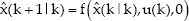
while the predicted covariance is estimated as
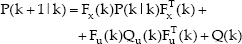
where Fx(k) and Fu(k) are the partial derivatives of f with respect to x and u respectively, Qu(k) is the covariance of the measurements of odometry and Q(k) is the covariance due to the error of the kinematic model. In practice, Qu(k) is calculated considering the standard deviations of the encoders, while Q(k) is empirically adjusted estimating the error of using the kinematic model.
The update stage or measurement update aims to correct the predicted state ○(k +1|k) and predicted covariance P(k + 1|k) using the measurement z(k+l) and the predicted measurement ẑ(k + 1|k) calculated by (1.3). Let the difference between the measurement and the predicted state be the innovation of the system υ(k + 1) = z(k + 1) - ẑ(k + 1|k). Since the commercial SICK NAV200 laser navigation system provides the state to estimate directly, i.e., the predicted measurement is the position estimate provided by the laser device ẑ(k +1|k) = h(x(k +1|k)) = ○(k +1|k) and the innovation of the system can be obtained by υ(k + 1) = z(k +1) - ○(k + 1|k).
Because the laser navigation device can provide outliers (referred to the tracked state to estimate) inducing divergences in the EKF, the measurements are validated using a test. Such a test consists of a sanity check to reject incoherent measurements. This is done by checking that the observation is located in the area limited by the covariance of the estimation.
The variance of each measurement is first calculated as follows,

and the measurement is then accepted if it satisfies the following condition

where g represents the difference between the measurement and the prediction of the measurement. This factor is usually expressed as an amount of the standard deviation, e.g., the number three is used to cover more than 99% of the confidence interval.
The covariance of innovation is then calculated as

where H(k +1) is the derivative of h(k +1) with respect to the state x(k +1|k) and R(k +1) is the noise model covariance of the position estimates provided by the laser navigation system.
The Kalman gain W(k +1) is then calculated, which only properly propagates the relevant component of measurement information as follows

The predicted state ○(k +1|k) and its covariance P(k +1|k) are then updated using the residual measurement υ(k +1) with the Kalman gain as follows

Figure 5 shows a schema of the implementation of the EKF, where each step is detailed and the flow of the calculations are specified.
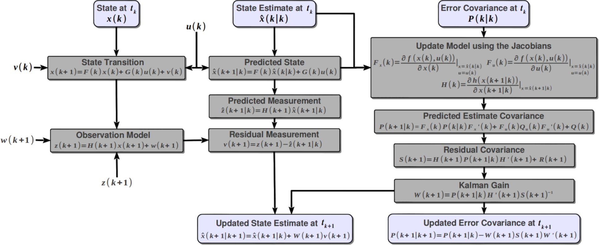
The schema of the implementation of the Extended Kalman Filter (EKF) in the localization approach.
In our implementation, both odometry (Qu(k), Q(k)) and laser position estimates (R(k)) noise models are adjusted empirically. The filter is initialized with the first estimation of the laser and the initial covariance has to be coherent with the sanity check g of measurements. The proper initialization of the covariance is of paramount importance because initial low values can make sanity checks very restrictive while initial high values can delay the convergence of the filter. The former can cause the measurements of the laser device to be ignored and thus unbounded errors of dead-reckoning are not corrected. The latter can estimate imprecise positions until the EKF converges, which does not permit manoeuvres to be achieved with the proper grade of accuracy, repeatability and reliability during this convergence time. Nevertheless, this period of convergence is usually several seconds for huge initial values of covariance. Therefore, priority is given to the convergence of the localization approach for safety reasons, i.e., the covariance is initialized with higher values than needed to ensure the convergence of the EKF. The odometry measures, received at 9Hz, run the prediction stage while the laser estimations, received at 1Hz, run the update stage. For safety reasons and to ensure the robustness of the localization approach the filter is reinitialized when a number of estimations provided by the laser do not satisfy the sanity check condition (1.7).
4. The path tracker
The path tracker method adopted by the industrial guidance system has to address the challenge of dealing with the important variation of the weight of the load that has to transport the AGV. Such a variation induces slipping and skidding effects that can make the control law used to address the problem unstable. Another key point is that control law oscillations can knock down the load, which gives rise to safety and performance problems.
The path-tracking problem of docking manoeuvres is especially complex because it has to satisfy the robustness constraints of industrial applications. The docking operations should be performed as fast as possible avoiding vibrations induced by eventual high jerk variations in control actions. These vibrations are critical for both the accuracy of the docking operation and for the stability of the load.
The different path-tracking approaches to address this problem can be classified, according to the model used to follow the path, into model-based [22] and non-model-based methods [23]. The latter obviates the complexity of AGV dynamics and the difficulty of obtaining the actual vehicle parameters. In this work, a vector pursuit controller [24] has been adopted because it provides remarkable tracking results when compared to other non-model-based control techniques [23].
The vector pursuit approach is a geometric path-tracking (pure pursuit) method that employs both distance and heading to a goal position (look-ahead) to calculate the curvature to move a vehicle from its current position to such a goal. This look-ahead position is usually obtained as the intersection between the route to follow and a circle of radius d centred in the local coordinate system {X1,Y1}, with d being the look-ahead vector. The proper selection of the module of this look-ahead vector is of paramount importance because large look-ahead distances reduce the control oscillations at the cost of increasing the position errors when high curvatures, while short look-ahead distances allow more accurate path-tracking, increasing the oscillations. Therefore, the choice of |d| should be decided as a trade off between accuracy and robustness depending on the specific application. More details about the path tracker method can be found in [24].
5. Experiments
The effectiveness of the proposed flexible industrial guidance system is tested by two experiments; the vehicle following a predefined navigation route and achieving a complex docking manoeuvre. The former permits us to model empirically the noise of odometry information and it shows the advantages of fusing the information provided by the laser navigation system with the information provided by odometry. The latter shows how the industrial guidance system permits the AGV to achieve complex tasks with the grade of accuracy, repeatability and reliability required by industrial applications.
As previously mentioned, the EKF has to be adjusted. The information provided by the traction and steering encoders is read every 115 milliseconds. On the other hand, the laser navigation system provides position estimates every 800 milliseconds. The standard deviation of odometry is empirically adjusted estimating: a standard deviation of about 0.2 degrees for the orientation using the steering encoder and a standard deviation of about 0.01m/s for the velocity using the information provided by the traction encoder. The position error of the commercial laser navigation system is about 1cm in positioning and 0.1 degrees in orientation. However, these position errors are significantly increased when the vehicle moves, especially when it turns, so the linear and angular velocities are used to consider this increase in the positioning error.
The path tracker also has to be adjusted, in particular the module of the look-ahead vector
6. Navigation experiment
The navigation experiments aim to evaluate the trajectory run using only dead-reckoning information, only position estimates provided by the laser navigation system and both sources of information. In order to do this, the AGV follows a closed-loop trajectory and a zigzag pattern, as shown in Figure 6. The closed-loop trajectory consists of tracing a path with the shape of an eight, which starts and ends at the same position. The zigzag pattern consists of a sinusoidal trajectory. Both experiments show the trajectory followed by the vehicle using only odometry (dead-reckoning), using only the position estimates of the SICK NAV200 and using the information fused by the EKF. For graphical clarity, the path to follow is not depicted because the position error using the EKF is of the order of centimetres and given the scale of the figure (in metres) the path flow is overlapped with the trajectory run using the EKF. Such a comparison is made in the docking experiment.
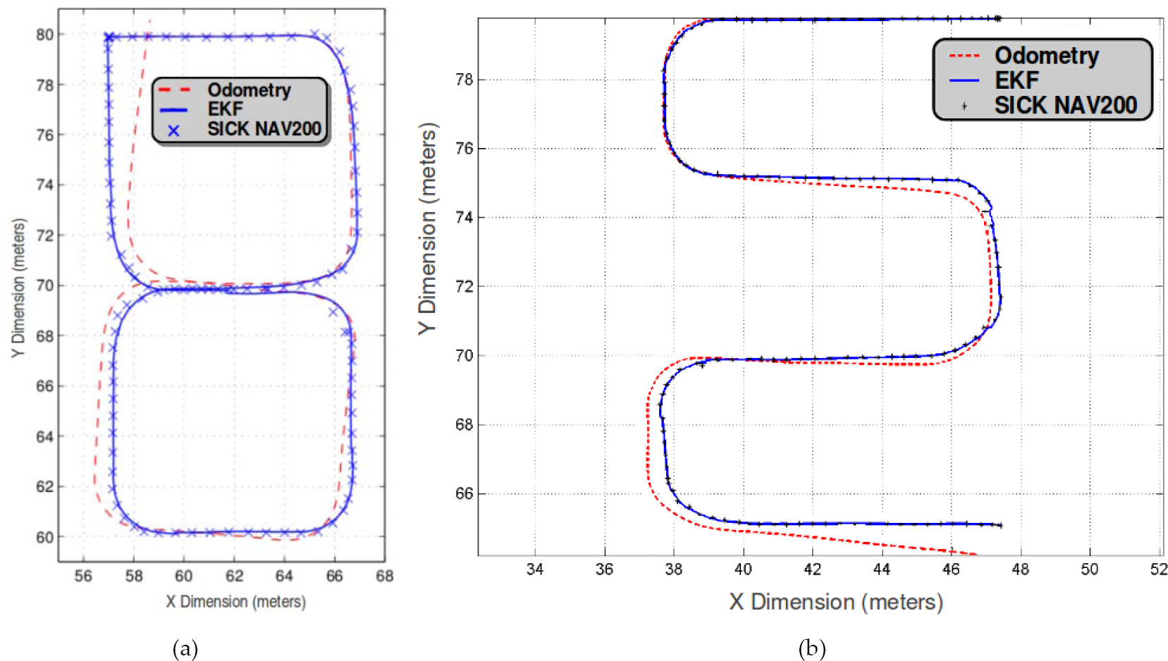
The navigation experiments using the industrial guidance system: (a) following a closed-loop trajectory and (b) tracing a zigzag pattern.
It can be seen that the position error using dead-reckoning is small when the vehicle is straight running, while it increases when the vehicle turns. This can be observed in the closed-loop trajectory (Figure 6(a)) where dead reckoning trajectory is similar to the position estimates provided by the laser device until the vehicle turns. It also can be observed in the experiment following the zigzag pattern (Figure 6(b)) that the position error of dead-reckoning significantly increases when a turn is performed by the vehicle. One can also observe that the position estimates provided by the laser device are less accurate when the vehicle turns. This is of paramount importance because load transfer operations usually require turning, and hence, these position estimates can induce collisions.
The trajectory run using the EKF is accurate and precise. The experiments show how the position error using both sources of information is reduced in the turns. Besides, the vehicle is able to end the closed-loop experiment at the initial position.
7. Docking experiment
The docking experiment aims to evaluate the industrial guidance system when the AGV is achieving a docking manoeuvre. This is the most complex and dangerous task that a free-ranging AGV has to perform because small position errors can induce collisions with the load or with the workstation. The docking manoeuvre needs a route to follow, which is usually generated in the guide-path networks design stage using the initial and final locations of the manoeuvre.
Path planners for wheeled mobile robots have been widely developed in recent years. However, many of them turn out to be unsatisfactory when implemented on real wheeled robots because of discontinuities in the path's curvature profile. Other path planners constrain the path to being continuous and try to solve the resulting optimal control problem. However, it can be proved that optimal trajectories for this kind of system involve infinite chattering. In order to avoid these problems, the proposal of [25] is adopted, which provides an efficient solution to generate sub-optimal paths with continuous curvature and a maximum curvature derivative.
Figure 7 shows the trajectory followed by the AGV using the industrial guidance system, the position and bearing errors following the path and the sequence of the load transfer operation. The docking manoeuvre is performed at a velocity of 0.35m/s, which allows the manoeuvre to be performed in 35 seconds. The industrial guidance system is able to finalize the load transfer operation with a position error of less than 1cm and an orientation error of less than three degrees. In addition, the position error is bounded in less than 4cm and the bearing error is limited to less than five degrees.

The docking experiment using the industrial guidance system: (a) the trajectory to follow by the AGV and the actual trajectory, (b) the positioning error, (c) the bearing error, and (d-f) the sequence of the docking manoeuvre.
8. Discussion
The experimental results presented in the navigation and docking experiments demonstrate that the developed industrial guidance system permits industrial vehicles to operate with the grade of accuracy, repeatability and reliability required by industrial applications.
The experiments presented in this work are focused on the evaluation of the effectiveness of the localization approach in order to permit the industrial guidance system to operate properly. Such a guidance system has permitted the development of flexible AGVs [16] able to operate autonomously in complex environments. These vehicles can operate independently [15] or as a Flexible Material Handling System (FMHS) [6] composed of several of flexible AGVs. More details and experiments on the integration of the proposed flexible industrial wireless guidance system with production systems to operate as a FMHS and artificial intelligent techniques to increase the autonomy and flexibility of AGVs, can be found in [1][2][6][15][16].
9. Conclusion
This paper has presented the development of an accurate and robust flexible industrial guidance system used to guide Automated Guided Vehicles (AGVs) in indoor industrial environments. The work focuses on the implementation of an EKF for fusing the position estimates provided by a commercial laser navigation system with dead-reckoning information.
The problem of using only the position estimates provided by the laser device is twofold: they are provided at a low rate and they are less accurate when the vehicle moves, especially when it turns. The former compromises the stability of the path tracker approach, while the latter does not permit the vehicle to operate with the grade of accuracy, repeatability and reliability required by some tasks, especially by load transfer operations. It is well known that dead-reckoning cannot provide robust and accurate position estimations because slip and drift errors are unbounded. The experimental validation shows that the implementation of the filter allows complex manoeuvres to be achieved with bounded errors in positioning and bearing, which are not possible using only one of the sources of information.
The robustness of the industrial guidance system is also increased by the implementation of the filter, which makes use of dead-reckoning when position estimates from the laser navigation device are not received for short periods of time. This can happen when less than three reflectors are detected at each time step. Accuracy is increased by reducing the position error when the vehicle turns. Finally, the flexibility of the industrial guidance system is attributed to the ability to modify the flow paths.
Footnotes
10. Acknowledgments
This work was supported by the Spanish Ministry of Science and Innovation under DPI-2004-07993-C03-02 and DPI-2007-66556-C03-02 CICYT projects. Special thanks to the company Frutas El Dulze SA for granting access to the facilities required for this research.