
Abstract
Omni directional mobile robots have been popularly employed in several applications especially in soccer player robots considered in Robocup competitions. However, omni directional navigation system, omni-vision system and omni-kick mechanism in such soccer player robots have not ever been combined. This situation brings the idea of a robot with no head direction into existence, i.e. a comprehensive omni directional soccer player robot. Such a robot can respond more quickly and it would be capable for more sophisticated behaviors such as ball passing or goal keeping. This paper has tried to focus on description of areas such as omni directional mechanisms, mechanical structure, control, optimized odometry system, omni-vision sensor for self localization and other subjects related to soccer player robot's software.
1. Introduction
The RoboCup competitions were first proposed by Mackworth in 1993. The main goal is to apply the methods and techniques from robotics, vision and artificial intelligence (AI) to create a successful team of robots for soccer play. Nowadays, the RoboCup is organized in several different leagues such as the simulator, the Small-Size, the Middle-Size and the Legged robot leagues (Kitano, 1997a, Kitano et. al, 1997. Kitano, et. al, 1998). The robots in middle-size league should only use local sensors and local vision. Each team can have a maximum number of four robots with a maximum footprint of 2000cm2. They can communicate with each other through a central computer via a radio link. The rules in the competition are the same as the international soccer rules as far as they are practical for robots (Kitano, 1997b).
This paper presents the design and manufacturing of an omni directional soccer player robot development at robotic centre of Isfahan University of Technology. The idea of an omni directional soccer player robot is not new in Robocup (Carlisle, 1983, Muir et. al, 1987, Pin et. al, 1994, Asama, 1995). However, construction of a comprehensive omni directional robot can be greatly extended the visual information and behavioral capabilities of such robots. Therefore, a new generation of mobile robots equipped with omni-navigation system, omni-kick mechanism and omni-vision system was designed and developed to create a non-oriented robot.
Recently, most conventional soccer robots have used a wheeled mechanism for their mobile system (Watanaba, K., 1998). Such mechanism consists of two independent driving wheels responsible for all needed robot motions (front-steering and rear-wheel driving mechanism). Motion restriction is a major problem in use of such mechanism in mobile robot (Watanaba, K., 1998). Omni directional wheels can provide suitable conditions and high mobility results in no motion restriction in the mobile robot.
In addition, using a modified odometry system, to prevent the slippage effects of driving wheels, accompanied by omni directional vision sensor presents a reliable and accurate self-localization method for any wheel-driving robot.
On the other hand, to optimize the rotation rate of the soccer robot, an omni-directional kicking system seems to be an appropriate method. Therefore, combination of these mechanisms creates a high flexibility soccer robot for the Robocup Middle Size competition. A picture of such robot developed for this purpose is shown in (Fig. 1).

A comprehensive omni directional robot having omni directional vision, motion and kicking system
This paper is organized as follow. Sections 2, 3 and 4 describe the kinematics, dynamics and control of the robot respectively. The perception technology of omni directional kicking system is described in section 5. Self-localization using both omni-vision and odometry is presented in section 6. The artificial intelligence algorithm in our robot, namely, AI Core, Role Engine and Behavior Engine are explained in details in section 7. Finally, section 8 concludes this paper.
2. Robot Kinematics
Omni directional robots usually use special wheels. These wheels are known as omni directional poly roller wheel. The most common wheels consist of six spindles like rollers which can freely rotate about their rotation axis (Asama, 1995, Watanaba, 1998). The body of each wheel is connected to the DC motor shaft. Therefore, a Robot with three omni directional wheels can equilibrate on plane easily and follow every trajectory.
Our Robot structure includes three big black omni-directional wheels for motion system and three small free wheels as feedback mechanism where shaft encoders are mounted on (Fig. 2).

Three black omni directional wheels act as actuators while three free wheels are for feedback.
2.1. Kinematics Schematic
Using omni directional wheels, the schematic view of robot kinematics can be shown as below (Fig. 3) (Kalmar-Nagy, T., 1998):
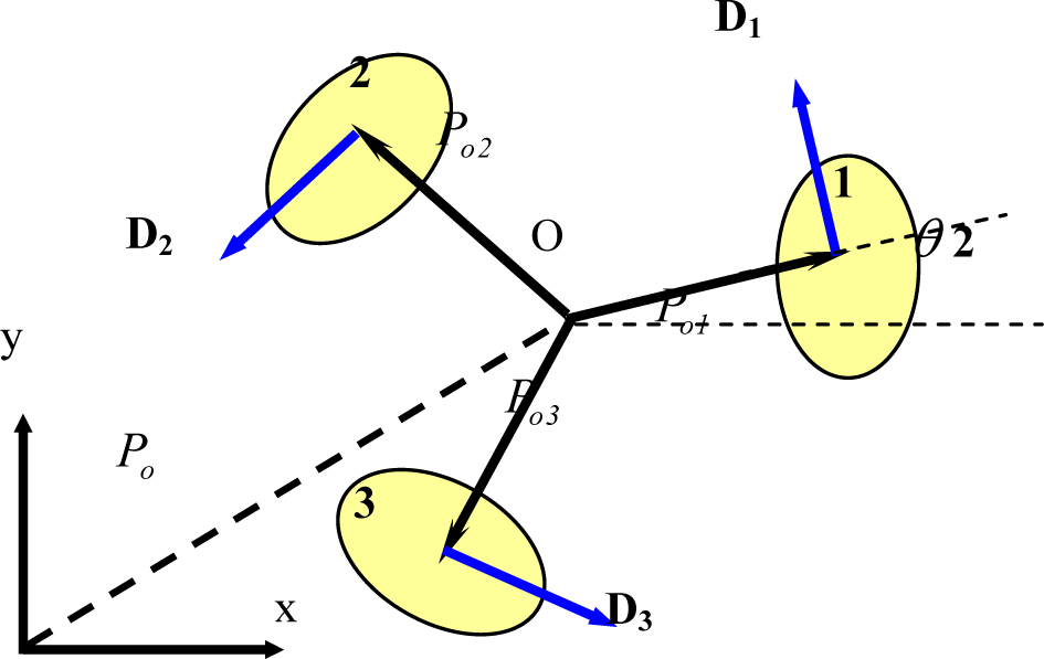
Robot kinematics
Where O is the robot center of mass, Po is defined as the vector connecting O to the origin and D is the drive direction vector of each wheel.
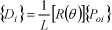
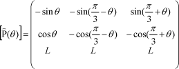
Using unitary rotation matrix, [R(θ)] defined as:

The positions vectors {Po1},…,{Po3} with respect to the local coordinates centered at the robot center of mass are given as:

The drive directions can be obtained by:
or

Where, L is the distance of wheels from the robot center of mass (O).
2.2 Linear and angular velocities
Using the above notations, the wheel position and velocity vectors can be expressed with the use of rotation matrix [R(θ)] as:
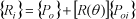
And

The vector Po = {x, y} T is the position of the centre of mass with respect to Cartesian coordinates. The angular velocity of each wheel can be expressed as:

Where, r is the system wheel radius of odometry. Substituting for {Vi} from equation (6) yields:

Note that the second term in the right hand side is the tangential velocity of the wheel. This tangential velocity could be also written as:

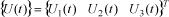
From the kinematics model of the robot, it is clear that the wheel velocity is a function of linear and angular velocities of robot center of mass, i.e.:

Or in short:

3. Robot Dynamics
Linear and angular momentum balance can be written:


where fi is the magnitude of the force produced by the ith motor, m is the mass of the robot and J is its moment of inertia.
3.1. The Motor Characteristics
Assuming no-slip condition, the force generated by a DC motor can be written as:

where f is the magnitude of the force generated by a motor attached to a wheel, and v is the velocity of the wheel. The constants α and β are motor characteristics and can be determined either from experiments or from motor catalogue.
Substituting equation (13) into equation (12) yields:
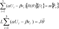
This system of differential equations can be written in the following form:

Where:
and
Note that Ui(t) is the voltage applied by supplier to the DC motors.
4. Robot Controller
Two identical PID controllers are used for controlling the robot position and orientation. The experiment showed that the system is robust enough for controlling a soccer player robot (Jung, M., 2001). P and D coefficients are adjusted manually to get a stable and desirable response.
4.1 Position Controller Architecture
In order to implement the position controller, the position error vector is determined as follows:

Where {V̄} expresses the output of the position controller for driving units, whose components on each driving wheel are extracted with:

4.2 Head Angle controller
Assuming that the head angle of the robot is β and the desired head angle is θ, the angle controller is then determined as follows.

where eθ = θ – β is the angle error of the robot.
4.3 Scaling
The output of the position or angle controller in equations (19) and (20) may exceed the range of the applicable voltages on the motors. In order to deal with such a situation, a scaling algorithm is proved to be efficient. If the output vector of position controller is out of range of maximum motor voltage (vmax), it will be scaled down with the following scale factor:

For the angle controller, another scaling method is used, in which the output of the angle controller is clipped to β.vmax (0 < β < 1). The reason for using such threshold is that a relatively high angle error would result in high motor voltages affecting the output of position controller.
4.4 The Final Motor Controller
The final applicable voltages on the motors are computed as:

The following scale factor is used for ui before being applied to each motor if max|ui| > umax:

5. Omni directional kicking system
In soccer player robot usually one direction is used for directing the ball to the goal or other destinations. Therefore, the ball handler and kicking mechanism is added in this direction which help the robot to get a suitable form for directing the ball. Although the conventional mechanism can work for any soccer robot, it has some limitations which causes additional movements especially in rotation of the robot. In other words, each robot has a special head for kicking the ball and must adjust it to the proper direction during the game. These adjustments in the single head robot increase its rotation significantly and reduce its maneuverability. In order to optimize such rotations, we use two extra kicking mechanisms to form an omni directional kicking system.
The position of these kicking systems is shown in Fig. 4. As it can be seen from the figure, each kicker is assembled between two omni directional wheels and forms a system with three heads in 00, 1200 and 2400 angles.

Omni directional kicking system of the robot
In an experiment carried out at our robotic centre, three types of soccer player robot in the form of 10 teams, which participated in Robocup, were examined in order to assess the rotation rate of each type.
In this assessment, the number of complete rotations for each robot in one minute was measured and the total average of them was then calculated. Fig. 5 shows these numbers for three types of robots, i.e.:
Two independent driving wheels mechanism
Omni directional navigation system (one head)
Omni directional navigation and kicking system (three heads)

Average rotation rate for three types of soccer player robots
There is a significant decrease in the rotation rate between the first type and the third type of these robots shown in Fig. 5. The number of complete rotation per minute for omni directional single head and three heads robot are 5 and 2 respectively. It shows that using the omni-kick system is very useful and can reduce the rotation rate in robots with the same navigation system about 60% percent. The low rotation rate in a robot simplifies the algorithm needed for following a trajectory, cooperative behaviors and increases the speed and flexibility for directing the ball to the favorite destination.
6. Self-localization
Odometry is a classic method, which can help mobile robots to determine their position and head angle (Chenavier et. al, 1992). Although this method has great advantages over other self localization approaches (i.e. vision based, laser range finders, GPS and etc), it suffers from great cumulative errors in long run (Stroup et. al, 2002). That is a major reason why this method is not widely used in mobile robots. Few corrections in such a method enable us to take advantage of its unique benefits such as simplicity, cost efficiency and short term accuracy. Traditionally odometry sensors are coupled with driving units in mobile robots. Separating odometry sensors from the driving wheels is thought to be a good solution for reducing errors such as slippage in the time of acceleration. This idea was implemented in our soccer robot by three separate omni directional wheels coupled with shaft encoders placed 60 apart of the main driving wheels (Fig. 6).

Separate omni directional wheel coupled with shaft encoders
Free shaft rotation and the flexible connection to the structure ensure minimum slippage and firm contact of these wheels to the ground, all of which result in a great improvement in output precision. Having the shaft-encoder values, one can extract the robot position and orientation from Direct Method. This method eliminates the differentiation and integration operations which are necessary in Differential Method.
Even sudden faulty reports of the vision self-localization algorithm can be filtered out using the position and orientation from the odometry system. Such a filtering at the proper time, the vision could calculate the position more reliably (Fig. 7). Therefore, we decided to combine these two methods (odometry and vision) in our robots in order to have a more accurate self-localization algorithm.

The combination of odometry and vision self-localization systems
6.1. Self-localization Using Odometry
As our robots used the Differential Method in Robocup German open 2003 competitions and the Direct Method for World RoboCup 2003 in Italy, thus in this section two self-localization methods based on shaft encoder outputs are introduced briefly, which are called Differential Method and Direct Method.
6.1.1 Differential Method
In this method, the outputs of shaft encoders are differentiated temporally to obtain the individual wheel velocities. Using the kinematics equations, the robot linear and angular velocities can be computed. By integrating these velocities, one can extract the robot position. The algorithm for this method can be described as fallows:
Using kinematics equation of the robot, i.e. equation 11, x, y and θ are the parameters to be computed by having φ i from the shaft encoders. Solving equation (11) using the inverse of W results:
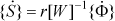
where φ i can be calculated from the current encoder samples.
Using numerical integration and knowing the initial position of the robot, one can easily calculate the new position of the system. Although this method is very simple, due to inherent differentiation operations, it is not reliable in long term. The main drawback of differential method is the error accumulation. Some of the important errors are: error in measuring time intervals, errors caused by the quantized nature of shaft encoders and output errors due to floating point computations.
Practically, time is divided into equal intervals, ΔT, in which the robot wheels' velocities are assumed to be constant. Considering these constant speeds, both robot linear and angular velocities are determined, and then the head angle and robot position would be estimated. The assumption of constant velocities in each time interval ΔT will cause some errors, which in turn will decrease the reliability of the computation results as the time passes. In addition, limited precision of shaft encoders will result in some kind of quantization errors, which itself leads to inaccuracy. To these errors, the error due to digital computations should also be added. In order to decrease these errors, one possible solution is to define ΔT as small as possible and to increase shaft encoder resolutions. It is clear that this solution will increase the CPU calculation which is not desirable.
6.1.2 Direct Method
The differential method was described as digitally differentiating the output of shaft encoders, applying the kinematics equations of the robot to the result of differentiation and integrating over the results. Because of quantized nature of the values in time, integration and differentiation cannot be implemented without approximation. If these operations could be eliminated and results could be driven directly from the measured angle by shaft encoders, more accuracy in calculation results would then achieved.
Using the equations of motion (18) in order to calculate x,y,θ directly, the following integral should be computed:

Where

System of equations in (26), results:

more simplification in the third equation results:

Having {φ} from the encoder, θ, x, y are calculated from equation (28) and the first two equations of (27) respectively.
6.2. Self-localization Using Omni-vision
Since the beginning of mobile robot, the map building was one of the most addressed problems by researchers. Several researchers used omni directional vision for robot navigation and map building (Kortenkamp, 1998, Menegatti, 2002). Because of the wide field of view in omni directional sensors, the robot does not need to look around using moving parts (cameras or mirrors) or turning the moving parts (Yagi, Y., 1999, Menegatti, 2002). The global view offered by omni directional vision is especially suitable for highly dynamic environments like the Robocup competitions. Several algorithms were presented for self-localization based on omni-vision data. In middle-size league, obvious objects such as blue and yellow goals are used for the robot to detect its positions. Because the robot height should be smaller than 80cm and the goal height is 90cm, therefore 10cm top strips of the two goals are seen by robots vision system during the competition period. Also the dimensions of the field and the goals are constant, using these values in addition to the angle of each robot with 2 vertical walls of goals, the position of robot will be obtained as seen in Fig. 8.

A Simplified Schematic for robot self-localization using omni-vision method.
As it is clear in Fig. 8, L and W are the field's length and width dimensions respectively and LG is the length of the goals. A robot which is illustrated as a black point in this figure, can see both goals with two particular angles a and b. Having, for example, angle a and the two ends of the blue goal, one can draw a unique circle as shown in Fig. 8. The same can be repeated for angle b and the two ends of the yellow goal. The position of robot is in one of the circles intersections. Note that the centers of circles are in a line that is perpendicular and passes through the middle of each goal.
Therefore, the position of robot will be obtained as:
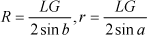
To find the center of the circles C1 and C2, we get:

Therefore, the equations of two circles are:

Solving two equations of (31) simultaneously, the intersection coordinates will obtain as:

The actual position of the robot is in one of the two points calculated from equation (32). The instant position of the robot will be obtained by information from odometry system and the previous location of it on the field.
6.2.1 Omni-vision sensor
The hyperboloidal mirror is a specific solution among the family of polynomial mirror shapes. These mirrors do not provide a central perspective projection, except for the hyperbolic one, but still guarantee a linear mapping between the angle of elevation φ and the radial distance from the center of the image plane ρ (Fig.8) (Gaechter, S., 2001).

Schematic diagram of the omni vision sensor
Another required specification is to guarantee a uniform resolution for the panoramic image. The resolution in the omni directional image increases with growing eccentricity, (ρ), when using a camera with an images of homogenous pixel density. (see Fig. 10)

a-Input omni directional image, b- perspective and c-panorama image (Yachida, M., 1998)
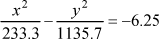
Searching through different articles and catalogues from various mirror-making companies; we found that they used the following hyperbolic curve for their omni directinal vision mirror (Ishiguro H., 1998):
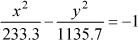
However, this equation is suitable for the mirror with large size and wide view. For our soccer player robot, we need an image with a diameter of 3.5m on the field, so to achieve a compact mirror with wide view, the above curve scaled down by a factor of 2.5 to yields:
Next, a special three stages process was considered for the mirror manufacturing:
Curve fabrication
Polishing
Coating
In the first stage the curve was fabricated on steel 2045 with CNC machining. Then, the workpiece was polished by a special process and finally Ni-P electroless plating was employed. To the best knowledge of the authors, such a method (electroless plating) was not used for mirror reflection so far.
6.2.2 World Model Construction
Although each agent tries to extract the real world map as accurate as possible, but “noisy data” and “non-global optimized” algorithms reduce the reliability of processed data. First, let us clarify what is meant by “noise” and “optimized algorithms” with a few examples in a mobile robot.
The flaws of color space modeling result in wrong color classification, which in turn makes the object detection algorithms prone to errors. As a result, a robot may not see an opponent because of its poor color table for the opponent's tag color, or it may see an orange T-shirt in the spectators' area as a ball! These wrong outputs are referred as “noise”. By this classification, the CCD noise pattern or faulty shaft encoder samples due to motors noise are excluded.
There is a trade off between speed and reliability in most algorithms. Middle size league in Robocup has a well-defined environment (e.g. distinct colors, defined sizes and etc), which can be very helpful in simplifying the design of a fast algorithm. Since a predefined environment is assumed, any changes in this environment can more or less result in wrong movements. For example, for self-localization the width of goals are assumed to be fully viewable in close situations; when an object taller than a robot (like a human) cuts or occludes a part of a goal in the image, the output of the vision self-localization module will not be reliable anymore. Detection of such a situation can be a very cumbersome task and making the algorithm very complicated and therefore slow. From the discussion above, it is apparent that multi agent data fusion algorithms are necessary for constructing a better approximation of the real world. In addition to the software which resides on each robot, stand alone software for network communication, world model construction, cooperative behavior management and game monitoring need also to be developed.
The world model module receives different data sets from every agent. Each data set contains different environmental information like self, ball and opponents' positions. Each data carries a ‘confidence’ factor; a larger confidence factor means a more reliable piece of information. The most recent data sets are then chosen for data fusion, in which the following rules and facts are applied:
Closer object are of more accuracy.
Objects further than a specific distance could be said to be totally inaccurate. (This distance is experimentally known)
An object in the field cannot move faster than an extreme value.
With respect to the above fact, the module filters unwanted duplicates of objects, (e.g. many opponents close to each other seen by different agents), calculates the best approximation for ball and opponents' positions with first order Kalman filtering, gives every object a confidence factor, applies a low pass filter on data and finally constructs a complete world model. This new world model contains information about the objects which may not have been seen by each agent correctly and also enhances approximations of all environmental information. The constructed world model is then sent back to all agents so they will have a better view of the world around them!
7. Artificial Intelligence Algorithm
The artificial intelligence algorithm in our robot has three distinct layers, namely, AI Core, Role Engine and Behavior Engine (Murphy, R., 2000). AI Core receives the computed field data from self-localization unit and determines the play state according to the ball position, opponents' positions and robots' positions. Determination of the play state is done by fuzzy decision-making to avoid undesirable and sudden changes of behaviors or roles (Weiss, G., 2000). Then it sends a set of roles assigned to the robots to Role Engine. In AI Core, roles are changed in a manner in which there is a relationship between new roles and old roles, therefore, robots never experiment sudden changes in roles (for example the role defense never changes to attack in the next cycle). Role Engine receives a set of roles from AI Core and provides the Behavior Engine with a set of behaviors for robots. Behavior Engine receives an array of behaviors from Role Engine and then according to the behavior each robot start moving with the help of trajectory unit. (Fig. 11)

Artificial Intelligence Algorithm
7.1 Trajectory
Each role has a special execution method, which gives a point and an orientation. Regarding the role of the robot, the output obtained after the execution of AI will be a set of vectors for each robot to reach. So the task of the trajectory will be to guide the robots through the opponents to reach the desired destination. The routine used for this purpose is the potential field method (Weigel T., 2002). In this method different electric charges are assigned to the robots, opponents and the ball. Then, by calculating the potential field of this system of charges, a path will be calculated and suggested for the robot. At a higher level, predictions can be used to foresee the position of the opponents and make better decisions to reach the desired vector.
7.2 Cooperative Behavior
Soccer is a team play and while the final aim of RoboCup community is to develop a team of fully autonomous robots which can play against humans, it is apparent that cooperative behaviors are of great importance. Currently there are a few approaches to address this issue, each one could be placed under of which the centralized or distributed regimes (Balch T., 1998).
Since the problem of artificial intelligence is not very complicated in this case, it is suitable to choose the centralized, role-based strategy. Each robot can accomplish a single task at a time which is called a behavior. One or more of these elementary behaviors, which are necessary to accomplish a single task, are grouped under a role. Sample behaviors are: Rotate, KickBall, CatchBall, RightDefence, etc. while Dribbler, Supporter and Defender are examples of roles.
In our approach a standalone server residing on a ground machine constructs an approximate world model. Then according to the world model, the GameState, and the playing strategy it picks three most necessary roles and assigns them to each active robot in the field. GameState is determined with two parameters.
The region in which the ball is currently inside.
The ownership status of the ball. (e.g. OurTeam, OppTeam, FreeBall)
For example a ball in the middle of the field, which is in our ownership, results in a MedAttack game status.
According to our overall strategy, there are predefined roles for each GameState, for example there can be Dribbler, Supporter and Defender in the MedAttack game state. The AI then assigns each role to the robot which gets the most qualification factor for that role.
In order to avoid unwanted bounces between roles of a single robot, there exist a hystresis module for each robot in the server software which accepts the roles decided by the AI, then from its past memory determines if the new role should be assigned or if the previous role is still the winner of the hystresis queue. This way the roles are somehow low pass filtered before assignment.
8. Conclusions
The performance of our robot team in RoboCup competitions 2003 (3rd place) showed that the combination of methods and techniques described in this paper are led to a successful soccer player team.
For the first time, omni directional navigation system, omni-vision system and omni-kick mechanism have been combined to create a comprehensive omni directional robot. This causes great reduction in robot rotation during soccer play.
The idea of separating odometry sensors from the driving wheels was successfully implemented. Three separate omni directional wheels coupled with shaft encoders placed 60 apart of the main driving wheels. The result was reducing errors such as slippage in the time of acceleration.
Combination of odometry and vision led to a more accurate and reliable self-localization algorithm.
A new mirror with a special coating technique was used to create a wide and compact omnivision mirror.