
Abstract
This paper mainly proposes absolute positioning instruments using camera positioning system and compass. The absolute positioning systems are used to estimate absolute position and orientation errors combined with estimated position and orientation from differential odometry integrated with gyroscope to calculate absolute position and orientation of mobile robot. In the method, the indirect Kalman filter is used to estimate absolute position and orientation errors and the estimated errors are fed back to odometry system, and also estimates some parameter errors to correct odometry system and gyroscope error. The simulation and experimental results show the estimated position and orientation of odometry system integrated with gyroscope, systematic errors of odometry system and gyroscope, absolute position from the camera positioning system and absolute orientation from compass compared with odometry system integrated with gyroscope.
1. Introduction
Typically, mobile robots behavior such as navigation, map building, the estimation of own position is very important. There are a lot of researches regarding the mobile robot in navigation (Maeyama, 1996; Borenstein, 1996; Hakyoung, 2001). The navigation system can be categorized in relative and absolute positioning systems. The relative positioning system estimates a current position by using the information about previous positions and velocities. Basically, the method of estimation for a wheel type mobile robot's position uses the wheel encoder called odometry system. However, in outdoor environment, the estimated position by encoder has the unpredictable error caused by traveling over an unexpected small obstacle or a bump under the wheels. In this case, the accuracy of the estimated robot's position is suddenly getting worse. The position error is detailed in differential equation either inertia measurement unit (IMU) or support sensors nowadays with some solutions in textbook (Britting, 1971). The analysis of navigation process from Kelly (Kelly, 2001) is under special consideration about systematic error and theory on navigation. Also the compensation of position's error with redundant sensors is discussed (Larsen, 1998; Chung, 2001), however always limits on some redundant support systems. Despite these limitations, most researchers agree that encoder is an important part of a robot navigation system and that navigation tasks will be simplified if encoder accuracy can be improved. For example, the map-based positioning system is the method in absolute positioning system by using environment as landmark. A mobile robot builds a local map by using onboard sensors and compares the local map with a global map. If the features from local map and the global map match, an absolute position of the mobile robot is computed. Researches on the map-based positioning have been mainly focused on creating an accurate local map and estimating the positions by a map matching techniques. Cameras are the most complex sensors recently utilized due to high computational and memory requirements, as well as high cost in robotics. On researches in robotic field are using either local or global vision. In global vision, the camera is used as external instrument to monitor area, which covers both of the robot and environment. The global vision is easy to realize and widely used such as in factory environments or in robotic filed, i.e. the popular competition of robot soccer. The absolute positioning system estimates a current position measuring the position from predefined positions. The position errors of the absolute positioning system are bounded, because the information on previous positions is not required. However the absolute positioning system cannot provide absolute position information along path because of absolute positioning instrument's cost and operation in large area. Therefore, a hybrid navigation system plays an important role in combination of the relative or absolute positioning system by selection one from each category. This paper proposes two main points. The first point is the integration of absolute positioning instruments in navigation process, which can support mainly differential odometry system. For the second point the navigation parameter with complementary support system based on indirect Kalman filter (KF) and with model of redundant error sources can compensate each other. The indirect Kalman filter can estimates the errors in the navigation and attitude information using the difference between inertial navigation system (INS) and external source data (Maybeck, 1979). The error model is separated between systematic and non-systematic. The different measurement of error level is performed by complement of redundant support system. For all relevant navigation parameters is with concept of relative and absolute support system in form of external redundant source. In scope of hybrid approach the differential odometry and support system for our purpose are combined that the navigation problem in real-time can be solved. By the experimental test sensor information are from real physical sensors. Section 2 describes the generally differential drive for mobile robot including encoder model. Section 3 explains the widely relative support of gyroscope. The absolute positioning systems, the CaPS and compass are explained in section 4. The hybrid navigation system is described in section 5. Simulations and experiments are presented in section 6 and finally concludes the paper.
2. Differential Drive for Mobile Robot as Main System
Generally, in navigation of mobile robot localization plays an important role. The robot's position is defined as

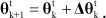
With the increment
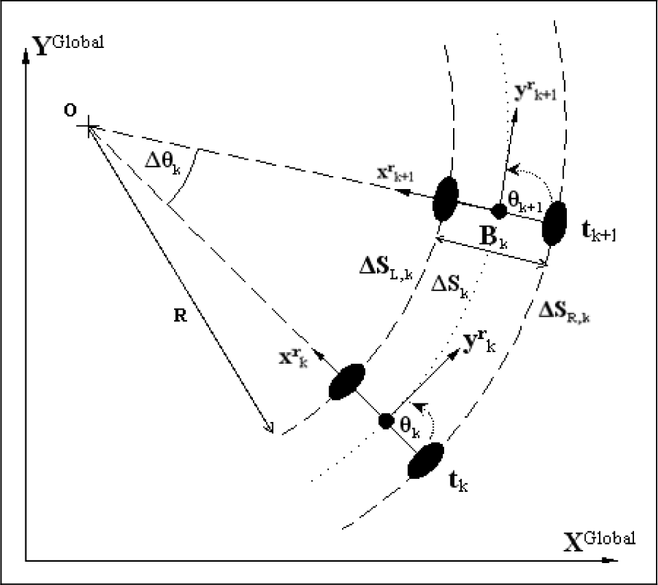
Kinematics relation between
2.1. Position error analysis
By the real robot path the parameter
2.2. Wheel-base (distance between drive wheels) error
The wheel base is distance between both drive wheels. The distance
This generates wheel-base error

Wheel base of a mobile robot
2.3. Wheel encoder model
The basic concept of odometry is the transformation from wheel revolution to linear translation on the floor. This transformation is affected with errors by wheel slippage, unequal wheel diameter, inaccurate wheel base distance, unknown factor and others. The real increment translation of wheel encoder is prone to systematic and some non-systematic errors.
2.4. Theoretical encoder model
The theoretical translation and rotation increment at the center of the robot is calculated by


Position extrapolation with theoretical encoder model is written as

and is detailed below


2.5. Practical encoder model
In practice encoders are prone to various systematic and non-systematic errors in the detection of


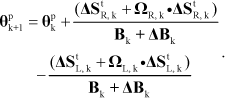
and from Equations (2), (3), (8) and (9) can be transformed in to a translation increment
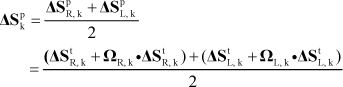
and rotation increment

Position with practical encoder model can be estimated as


Firstly, the error state


with the assumption that

Gyroscope CRS03 with temperature compensation.
2.6 State space of navigation system
A first-order linearization of Equations (15)–(17) can be evaluated by Jacobians method and the result of navigation system matrix is detailed as Equation (18) in appendix. The state variable, using
3. Differential Odometry Integrated with Gyroscope
The creation of relative support for differential odometry is the compensation both translation and rotation increment. The relative support can compensate error from odometry system for translation and rotation increment. With compensation the relative support system can reduce errors generated by noise. This paper presents also relative support system of rotation increment
3.1. Gyroscope model
Many researchers on robotic field work on about gyroscope sensor (Komoriya & Oyama, 1993). The theoretical gyroscope produces rotation increment in time interval k defined as

The practical gyroscope output

is corrupted by the scale factor error

The scale factor error

The error state vector is calculated by subtraction of the theoretical orientation value from practical orientation value yields the error orientation propagation

3.2. State-space model of gyroscope
From a first-order linearization equation of gyroscope, the resulting time-variant perturbation model can be obtained by

The state variable, using
3.3. Combination of state-space localization model between odometry and gyroscope
The combination of state space model can be written as

and detailed as Equation (26) in appendix.
3.4. The combination of odometry system and gyroscope by using different measurement model
The different measurement (Komoriya, 1994; Park, 1998) is calculated by

Therefore from Equation (27) the different measurement of rotation increment from the encoders and gyroscope is written as

and detailed as Equation (29)–(30) in appendix. General form of different model between odometry system and gyroscope can be written as

where vk is the measurement noise.
4. Absolute positioning system
Absolute positioning systems use the geometry relation between the position and environment map. From the geometry measurement the Cartesian coordinates (X, Y, θ) can be specified under certain assumption. If the position of the geometry reference is known, the position of mobile robot can be calculated usually with good accuracy. Some methods have been proposed for robot position reference. One of them has designed landmarks placed at specified positions with respect to the reference coordinate system. The current position and orientation of the robot can be obtained by geometry transformations between robot sensors and these landmarks. Kabuka and Arenas (1987) researched on absolute positioning by using barcodes. Many papers on the evaluation of a low cost gyroscope for application estimation of mobile robot systems were presented. However, other absolute sensing information and accurate error model for inertial systems still needs. In this paper two absolute positioning systems are proposed.
4.1. The CaPS - Camera Positioning System
The design of navigation algorithm for mobile robot needs knowledge about ground truth. In order to quality of the estimated position

The concept of absolute positioning system has more from experiment and commercial system. In closed environment, ultrasonic for robot's positioning can be used, but the system has some disadvantages (Werd 1997).
4.1.1. The CaPS Concept
Generally, machine vision is used to identify the position of objects to be manipulated by a robot, but this paper has purpose to identify the position of mobile robot by using overhead camera shown in Fig. 4.

The
First principle dealt with the method to establish the relationship between image coordinate reference frame and the real-world coordinate reference frame. The information transformation is shown in Fig. 5. Point Q in a three-dimensional space, referenced to frame R, is projected onto the image plane of the single camera. The electrical signals, picked up by the imaging sensor of the camera, will be converted into an analogue image. If the camera's output is not digital, the image digitizer will convert analogue image into a corresponding digital image. Finally, the digital images from the image digitizer will be the input to the process of geometry measurement in the single camera system. If the image feature q can be detected, then the coordinates of point Q will be determined. This is called the inverse projective-mapping. It is necessary to know the coordinates of image point q are related to the coordinates of corresponding object point Q, which is referenced to frame R.

Relationship between Camera frame, Image plane and Reference frame.
4.1.2. Forward Projective-Mapping
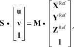
The forward projective-mapping needs to determine coordinates (u, v) of its image point q in the image array, which is referenced to index coordinate system of u and v. The coordinates (XRef, YRef, ZRef) of point Q is referenced to frame R. The frame C is assigned to the camera, as shown in Fig. 5. If motion transformation CTR describes the transformation from reference frame R to camera frame C, then the coordinates of point Q with respect to camera frame C are

The relationship between index coordinates (u, v) and the corresponding coordinates (XC, YC, ZC) with respect to camera frame C. This relationship is detailed by projective-mapping matrix ITC as below

where S is scaling factor.
The combination of these equations yields

This equation describes forward projective-mapping. The coefficients inside ITC are called the camera's intrinsic parameters, while the elements in CTR are called the camera's extrinsic parameters. It can be denoted as

matrix M is known as the camera's calibration matrix, which is a 3×4 matrix.
4.1.3. Inverse Projective-Mapping
From the Equation (35)–(36) is written as below
then the coordinates (XRef, YRef, ZRef) can be determined, if image point (u, v) are given. In Equation (37), the scaling factor S is unknown. In order to obtain a solution, it is necessary to have at least four constraints. Otherwise, there will be an infinite number of solutions for the unknowns (XRef, YRef, ZRef) and S. It is clear that one image point will impose only three constraints on the four unknowns. In order to have a unique solution, there are two possible ways to proceed: a) to increase the number of constraints, or b) to reduce the number of unknowns. The camera model is used to map a three-dimensional world point to its corresponding two-dimensional image point and on the contrary to identify the three-dimensional world point corresponding to a particular two-dimensional image point. For this paper, the camera model is considered as linear (Ballard and Brown, 1982).
4.1.4. The CaPS components
The DFW-SX91G is equipped with a 1/2 type 1,440,000-pixel CCD and offers SXGA resolution images. The model incorporate a variety of convenient features such as partial scan (16 × 16 zones), selectable output modes (image size/frame rate) and an external trigger function with an exposure range from 1/100,000 to 17.4 seconds, allowing for the clear capture of fast moving objects or still images in low light environments. The camera is placed in the overhead off-board position, 3m directly above the center of the workspace. The optical axis of the camera is perpendicular to the workspace of the robot. The robot workspace is an area of 3200mm × 2400mm. The camera is connected to a computer via IEEE 1394 interface. After choosing the camera, it is also important to check the availability of suitable lenses. The following formulas are used to calculate the focal length of the needed lens as proposed by (Sony Corporation, 2004).


With the 0.4 inch in CCD-format, CCD-width 6.4 mm and CCD-height 4.8 mm and Equation (38) and (39) yield


, so the focal length of camera can be 6 mm. Finally, we select the H612A (KA) C-mount Pentax lens with the 6 mm of focal length for the DFW-SX910 camera.
4.1.5. Algorithms
The image processing is done using Intel Open Computer Vision (OpenCV) library. The OpenCV library is a cross-platform middle-to-high level Application Programming Interface (API) consisting of more than 300 C-functions and few C++ classes that implement image processing operations and some popular image processing algorithms. The software algorithm of the image processing module is described in Fig. 6. The first step of the module is to acquire images by an overhead CCD camera sensor. The images are sent continuously from the camera to computer via IEEE 1394 interface. The second step is to perform a color threshold to identify static obstacles, moving obstacles and background. The images from camera are converted from RGB to HSV. The result is an image consisting of binary pixels. The third step is to create region of interest containing obstacles by removing noises and fill true regions. The fourth step is to correct data from pixel coordinates to real world coordinates. The fifth step is to determine parameters including locations, directions, and sizes. The last step is to send all resulting data to next module and user interface.
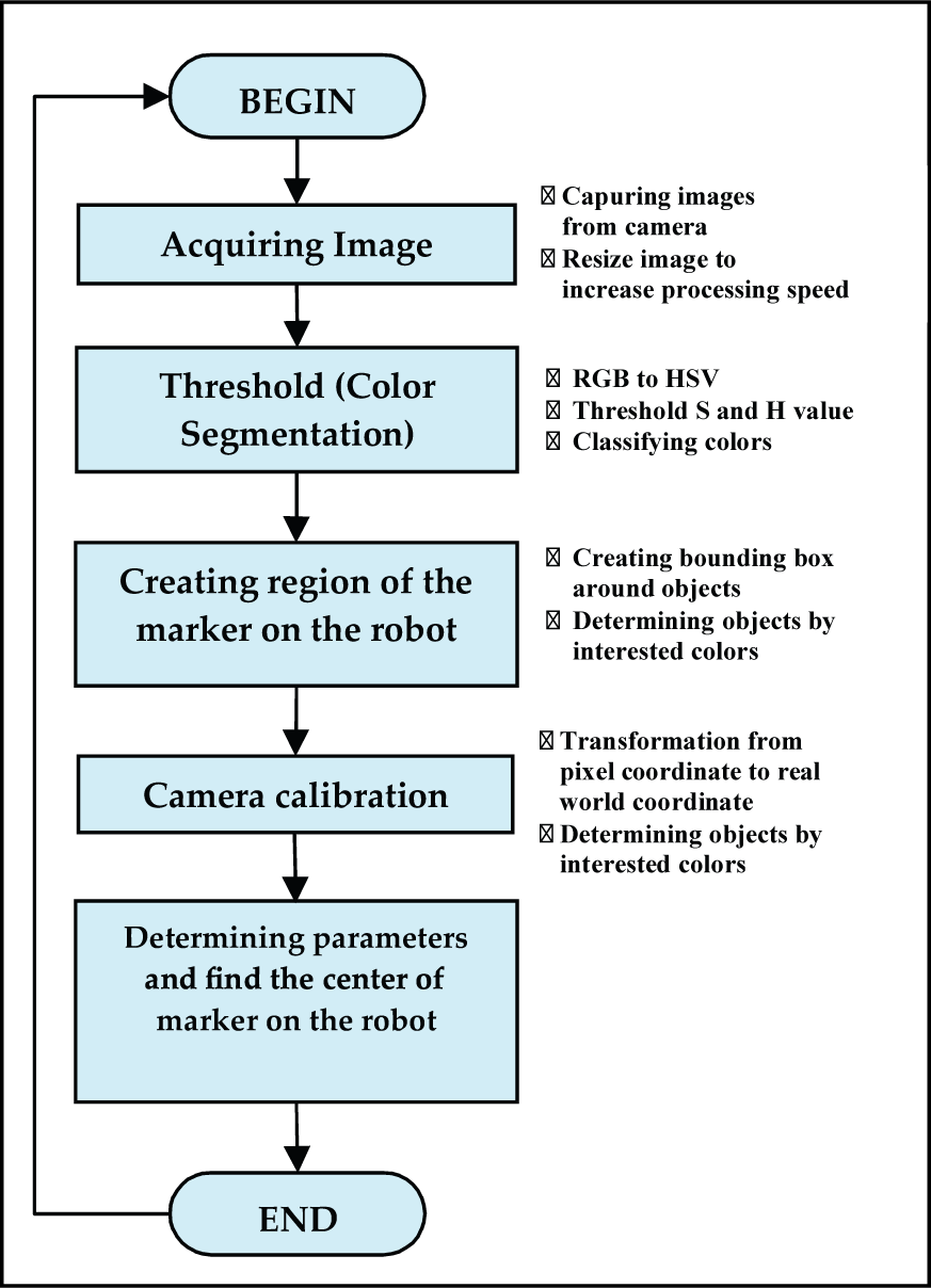
Flowchart to determine parameters and find the center of marker on the robot
In Fig. 6 after threshold and classification, an image consists of binary pixels. The value of each pixel states if the pixel is of interest or not. So, the regions of interest are found easily. To reducing noises, only regions, that are large enough, are taken. After finding the regions of interest on the mobile robot, the regions are bounded in bounding boxes. From these bounding boxes, we can determine the parameters of interest in pixel coordinate such as the position of robot's marker.
4.1.6. Camera calibration
To transform the image coordinate to the real world coordinate, the camera needs to be calibrated. If some camera's extrinsic parameters are unknown, calibration matrix M will also not be known even if its intrinsic parameters are available. Without the calibration, it is not possible for monocular vision to make any interest geometry measurements. Thus, it is necessary to estimate calibration matrix M using a process commonly known as camera calibration. In our work, the coordinates ZRef in a reference frame are not importance, if all are equal. The robot runs on the smooth floor, which can be treated as two-dimensional (2-D). This is because their locations are uniquely determined by two coordinates with respect to a frame assigned to the smooth floor. These two coordinates are sufficient to find robot's position. Refer to Equation (37). If we set ZRef = 0, the equation becomes

The calibration matrix M, which can be normalized by its element m34, is expressed as

and from Equation (41)–(42) can define a 3 × 3 matrix M' as

From Equation (42)–(44) can be rewritten as
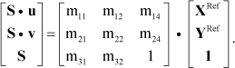
From Equation (45) can be formulated in another form as

where

and

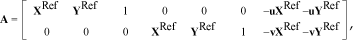
The Equation (46) describes the linear relationship among vectors A, M and B. The coordinates (XRef, YRef) of a point in a scene, and its image coordinates (u, v) are known, Equation (46) imposes two constraints on the eight unknowns in vector M. In order to derive a unique solution for the eight unknowns in M, we must have at least eight constraints. Since one pair of {(u, v), (XRef, YRef)} provides two constraints, it is necessary to have at least four pairs of {(u, v), (XRef, YRef)} in order to calibrate a camera. Assume that a set of n pairs of {(u, v), (XRef, YRef)} are available (n ⩾ 6). The optimal solution, which minimizes the squared error of Equation (46), is obtained as

In our work four points R1 = (x1, y1), R2 = (x2, y2), R3 = (x3, y3), R4 = (x4, y4) are selected in real world space to calibrate the camera. They correspond to four image points I1 = (u1, v1), I2 = (u2, v2), I3 = (u3, v3) and I4 = (u4, v4) in the image space, so the matrix equation can be defined as
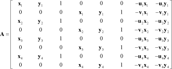

and

The Matrix M can be solved by using PMADE software as shown in Fig. 7.

PMADE software developed for Matrix M parameter solving
After the calibration matrix can be determined, the real world coordinate from a pixel (u, v) in the image space can be calculated from Equation (45). If we eliminate unknown S in Equation (45), then the equation is written

and then

Finally, the robot's position (XRef, YRef) can be determined

In this section the CaPS is in IKF-algorithm integrated. The absolute position of mobile robot is calculated from the CaPS and then fed to IKF algorithm. From Equation (56) the absolute position (XRef, YRef) of the robot can be generated from the CaPS. This absolute position from the CaPS will be compared with the absolute position from odometry integrated with gyroscope by using difference measurement of absolute position. The navigation method about absolute positioning system needs the environment map to localize the object's position. In case of the CaPS, the navigation system of mobile robot does not need environment information, because the robot's absolute position is directly measured as

The CaPS can generate absolute position (

By subtraction Equation (58) from Equation (57), a different measurement equation for position error is obtained by

4.2 Absolute orientation support with electronic compass
Kim (1996) described the experiments on orientation recovery of mobile robot by using compass. Ojeda, L. (2000) discussed on the use of electronic compasses in mobile robots with different error sources and solutions to correct these errors. In this paper the CMPS03 compass module shown in Fig. 8 is used, specifically designed for mobile robot as an aid to navigation with resolution ± 0.1° (Surachai, P., 2008). The compass can generate direct the output of absolute orientation (
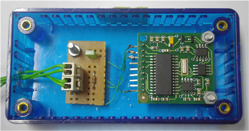
The CMPS03 compass module
5. Hybrid Navigation System from Absolute Positioning System
This paper presents the systems of main differential odometry integrated with gyroscope in mobile robot.
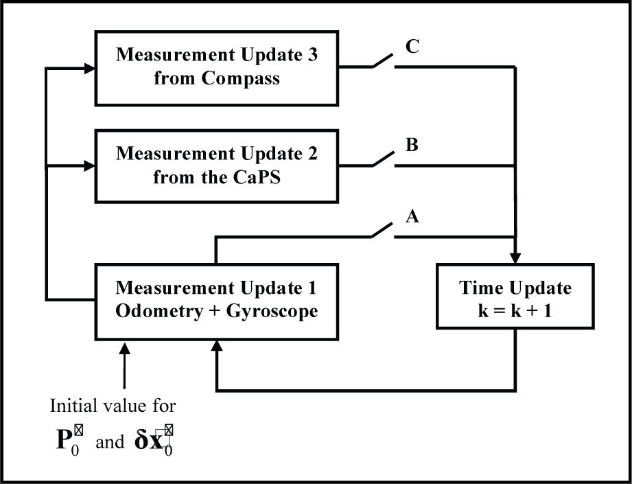
IKF loop the combination of support system and odometry system in measurement step
Gyroscope generates rotation increment used to compensate rotation increment from differential odometry. The absolute positioning system for orientation
5.1. The combination of odometry integrated with gyroscope and the CaPS
A state equation from basic odometry integrated with gyroscope is obtained by Equation (26) in appendix. The measurement equation

Then the measurement matrix of Equation (61) is

, where
5.2 The combination of odometry integrated with gyroscope and compass
Same as the combination of the CaPS, the state equation is obtained by Equation (26) in appendix. The measurement equation

Then the measurement matrix of Equation (63) is
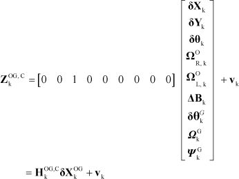
, where
5.3. Overall structure of navigation system diagram
The main odometry integrated with gyroscope system and absolute positioning instruments is shown in Fig. 10 in appendix. The different measurement of absolute position between the CaPS and odometry system integrated with gyroscope is used as measurement value in IKF loop to estimate the absolute position error.
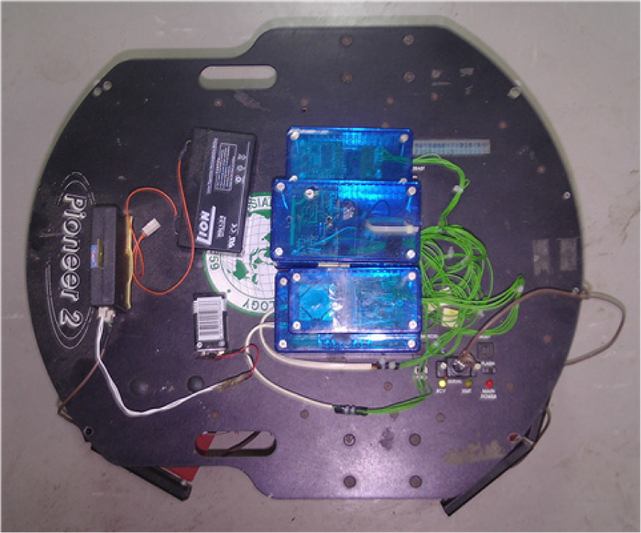
Pioneer-II integrated with gyroscope and compass
To estimate the absolute orientation error, the different orientation between compass and odometry system integrated with gyroscope is used as a measurement value in IKF loop. In IKF loop error parameters of main system are also estimated and fed back to correct encoder error and gyroscope error.
6. Simulation and Experimental Results
The navigation error state from odometry
6.1. The result of combination with gyroscope Support
The mobile robot (Pioneer-II from active media company) driven by differential odometry system integrated with gyroscope and compass shown in Fig. 11 is used for experiment in square shape 2.5×2.0 m. In experiment the robot starts at the position coordinate (x = 0, y = 0, θ = 0°) and runs from start point in right direction and returns at the start point again with speed 0.2 m/s. From experiment the robot's final position from odometry system are

Position generated by encoders is shown in cyan line and the blue line shows the position estimation of the robot by using different measurement of rotation increment between encoders and gyroscope with IKF algorithm
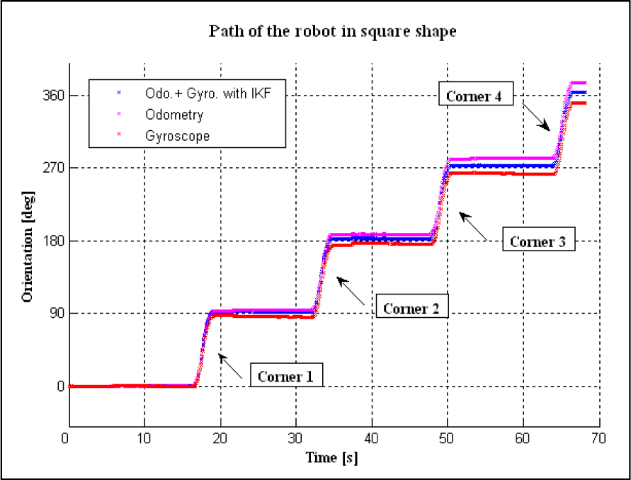
Orientation of the robot in four corners with counter clockwise running

Different orientation between odometry system and gyroscope
6.2 The result of combination with the CaPS support

Systematic error of odometry system
In this section, details the powerful IKF algorithm with the CaPS support. The CaPS concept is more details in previous section. In Fig. 17 shows the graphic of robot's trajectory in square shape from the CaPS compared with the reference point.
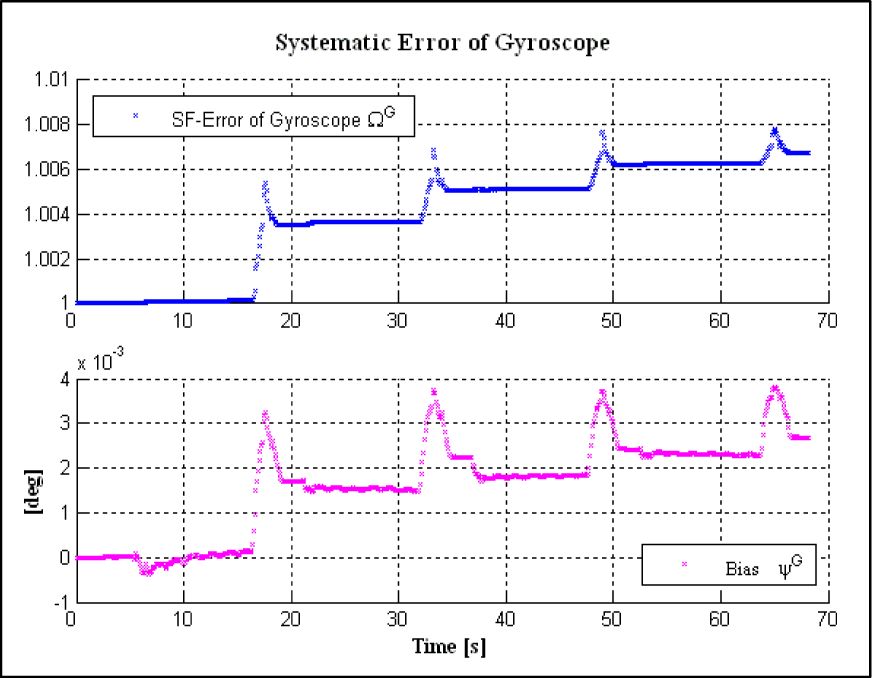
Systematic error of gyroscope
Details the systematic error of odometry system and gyroscope.

The different measurement of position
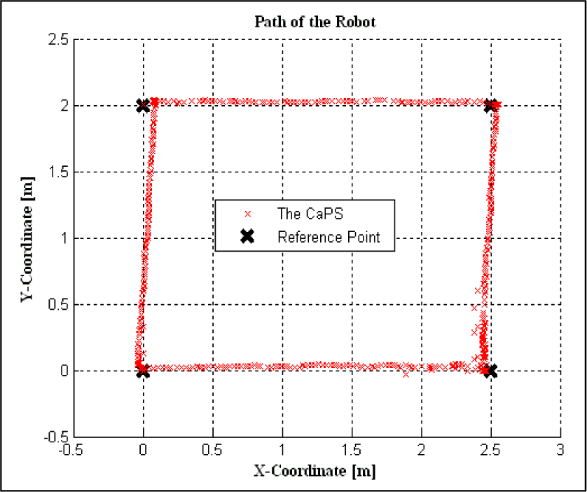
Absolute position generated by the CaPS compared with the reference position.
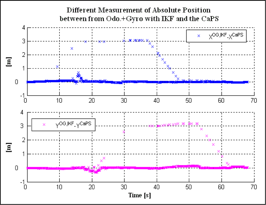
Difference absolute position between estimate positions from odometry integrated with gyroscope and from the CaPS.

Implement of the CaPS positioning system in IKF algorithm for estimate of robot position in global coordinate.
For the navigation algorithm the reference position plays an important role. To reduce position error of odometry, the reference position must be known to find the difference position between odometry system and reference position in time.
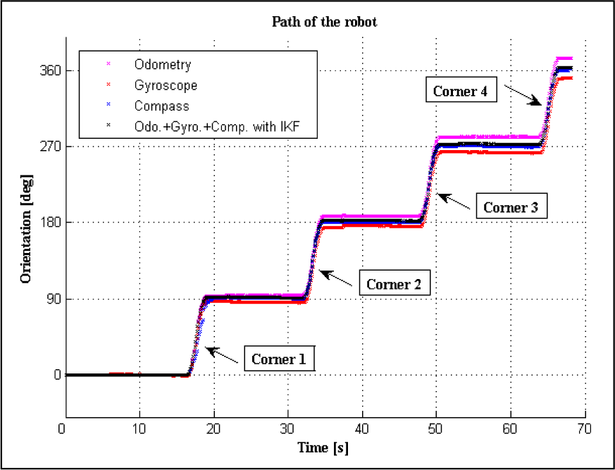
Orientation of the robot from odometry, gyroscope, compass and the combination of main odometry system integrated with gyroscope and absolute positioning by using IKF algorithm.
Generally the reference positions are constructed by manual measurement, which is difficult and not possible to measure the reference position in time. But the CaPS can generate the reference or absolute position compared with position from odometry system in the same time. In Table 2 shows the results of final coordinate of robot trajectory compared with actual reference coordinate.
Results of the final position of mobile robot in comparison to ideal coordinate.

6.3 Result of combination with compass
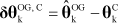
This section explains the results of the orientation of mobile robot with gyroscope and compass support by using IKF algorithm as shown in Fig. 20. The cyan line represents the orientation from odometry, the red line from relative support of gyroscope, the blue line from absolute support of compass and the black line shows the combination of odometry system, gyroscope and compass by using IKF algorithm. The estimated orientation θ̂OG,IKFk is obtained from odometry with gyroscope support by using the first measurement update. The different measurement of θ̂OG,IKFk and

Different absolute orientation between from main odometry integrated with gyroscope by using IKF algorithm and from compass.
7. Conclusion
This paper proposed the hybrid absolute positioning system using the CaPS and compass for odometry system integrated with gyroscope for mobile robot in an indoor environment. The CaPS provides position information to reduce the position error due to the main odometry integrated with gyroscope error. To reduce the absolute orientation error compass is combined with odometry system integrated with gyroscope. The indirect feedback Kalman filter (IKF) is used as the combination of odometry system, gyroscope and the absolute positioning system to estimate and compensate errors. The IKF can estimate the error of estimated absolute position and orientation by using the information from the CaPS and compass. Then mobile robot's position and orientation are obtained from addition of the estimated position and orientation error with the estimated position and orientation from main system. Also the IKF estimated the scale factors of the encoders, the distance error between wheels and scale factor and bias errors of gyroscope to correct errors from encoders and gyroscope. The simulation results show that the IKF can give precisely estimated position and orientation by using absolute positioning system. Further research aims to support the translation increment for odometry system with an accelerometer. The complementary measurement between translation increment from encoder and accelerometer can be passed to the filter.
Appendix


Overall combinations of support system and odometry system