
Abstract
The design of a mobile microrobot based on standing and travelling waves is proposed and analysed in this paper. Numerical modelling based on the finite element method is performed to find the resonant frequencies and modal shapes of a microrobot, and to calculate the trajectories of the upper points' movements under an excitation scheme. Geometric Path-Planning Algorithms for a piezoelectric hemispheric microrobot and an experimental study of this are presented in this paper.
1. Introduction
In many applications, it is very important to be able to precisely manipulate and position different types of objects which have a resolution in the nm range. Microassembly in production, cell manipulations in medical research, eye and plastic surgery are just a few good examples [1]. For this reason, the ‘flexible microrobots’ or ‘desktop micromanipulation systems’ are currently of interest. Like conventional robots, microrobots are very complex systems using various types of microactuators and microsensors. They are provided with algorithms for intelligent signal and information processing. Microrobots also move, apply forces, manipulate objects, etc. Some drive principles from the macro world can be applied to the micro world, but a possible scale down effect must be taken into account; otherwise, performance data may be calculated for a scaled down micromachine which are not realistic. With the exception of the specific microworld problems and the size difference, the design criteria and steps taken to build micro- or macrorobots in many cases can be identical. As with the design and building of a macromachine, the functional components of a microrobot must be first produced to the desired dimensions and internal structures before being assembled and fine-tuned [2, 3].
Microrobots have evolved into an important field with a great application potential, including micro-machining, micro-manipulation and micro-assembly in micro-factories, inspection and exploration of small environments, micro-surgery and bio-medical tasks inside the body, study of cooperating systems, and so on [4]. A significant interest in miniaturized robotic systems has recently been spawned by various applications including inspection, miniature manipulation, exploration, as well as search and rescue. Since many of the concepts and tools that have been developed for traditional robotic systems cannot typically be scaled down to the meso, micro or nanometer size of recently conceptualized miniature robots, researchers have been actively investigating new methods for robotic manipulation and locomotion [5]. High-precision positioning is essential in a wide range of fields such as precision measurement, machining and semiconductor-based manufacturing. Most of the high precision positioning devices that have been developed are driven by piezoelectric actuators, which have high resolution, high stiffness, quick response and so on. However, the strokes of piezoceramics are extremely small [6].
U. Rembold and S. Fatikov presented a robot called SPIDER-II [1]. This robot used nine piezoelectric bimorph motion changers that worked as robot legs. At the end of the 9th decade the NanoWalker robot (NanoWalker project), with the three feet laid out in a pyramid principle, was created in the USA [7, 8]. Such an approach was chosen due to the maintenance of stability during motion.
Scientists from various European universities of the project Miniaturised Robot for Micro Manipulation (MINIMAN) made a big input [9]. In 2000 a robot named MINIMAN III was presented. It consisted of a platform with three piezo legs that bended in any direction while exciting electrodes of different voltages. In 2002 the scientists U. Simu, S. Johansson and others from the same project introduced the robot MINIMAN V, built from two monolith piezoceramic parts, placed on each other's backs [10]. The lower part is dedicated to motion by plane; on the upper part, a ball is placed which has a special tip for working with objects. Each piezoceramic part has 6 feet, which move in four perpendicular directions.
In 1989, R. Bansevicius and K. Ragulskis were the first to present 6 and 9 degree of freedom microrobots that consisted of two kinematic pairs: a piezoelectric cylinder – passive sphere, a piezoelectric disc – passive plane [11]. R. Bansevicius demonstrated a simple application of a piezoelectric motor in the creation of mass-consumer products such as LEGO™ blocks and figures [12, 13].
In this paper we introduce a piezoelectric hemispheric microrobot with two alternative electrode schemes for generating a travelling wave and a standing wave. The trajectories of contact points are analysed and the possibilities of moving objects are shown when these excitation schemes are used. Commonly-analysed motion trajectory formation methods for various types of robots are used such as polynomial interpolation [14, 15], interpolation by splines [16–18] and Cornu spiral [19]. However, all those methods are not acceptable, so a new geometric path-planning algorithm was created and its application with a piezoelectric hemispheric microrobot is presented in this paper. Finally, an experimental study is also presented.
2. The Design and Operating Principles
During the research on object positioning, a piezoelectric hemispheric microrobot was created. The piezoelectric hemisphere microrobot consists of a cut spherical piezoceramic element and three magnetized steel cylinders, which are attached to a piezoceramic plate. (Figure 1). The angle between the cylinders is 120 degrees. The hemisphere's and cylinders' geometrical parameters are given in Table 1 and the properties of the materials used for the piezoceramic element are listed in Table 2.
Piezoelectric hemispheric microrobot: a) prototype;b) general scheme
The hemisphere and cylinders geometrical parameters

Properties of the hemisphere microrobot
One electrode is a one-piece and the other is divided into equal sections whose number is a multiple of three (3, 6, 9…), because the system is statically defined and such a division of electrodes allows an excite slider to move in any direction and rotary motion. Statically undefined systems (for example, the number of segments equal to 4) may also be used, but it also increases the geometric accuracy requirements of a converter, which increases its cost.
Movement is controlled by switching the excitation zones (Figure 2). If one electrode sector is excited at a time, a standing wave is induced. It generates a rectilinear motion. If all the segments of the electrodes are excited and voltage phases of each electrode differ by 120 degrees, the travelling wave and generated rotary movement are induced.
Electrode exciting scheme for standing wave generation
In summary of the theoretical analysis, we can state that the direction of the motion of mobile microrobots depends on the active excitation zone; i. e., a microrobot can move only in straight lines or rotate. However, microrobots of this type are different from others because they can perform motions at an angle; i. e., move in broken trajectories. Moreover, they have a high-resolution motion and wide speed control range.
3. Finite element method and results
Finite element modelling was used to perform modal frequency and harmonic response analysis, to calculate trajectories of the contact point motion using different excitation schemes for the electrodes. Figure 3 demonstrates the FEM model of a hemispheric piezoelectric robot.

FEM model of the hemispheric microrobot
Intrinsic modal shapes of the piezoelectric robot must combine radial (axial) and transverse shapes. Based on the results from the modal analysis, the suitable modal shapes that were defined were 48.89kHz (Figure 4). In modal shapes the radial form dominates. The contact elements are at the 1/4-wavelength and therefore receive the maximum relative displacements in the radial direction.

Modal shapes of hemispheric piezoelectric robot: 48,89 kHz
Harmonic response analysis was performed with the aim of finding out the microrobot's response to the sinusoidal voltage applied to the electrodes and to calculate the trajectories of the contact point's movement.
Resonant frequencies of 53 kHz were defined from harmonic response analysis. The trajectories of contact points with these excitation frequencies were calculated. The results of the calculations are presented in the Figure 5.

The trajectories of the contact point movement in the xz plane when the first excitation scheme is used
From the results presented it can be seen that using the first excitation scheme at 53.0 kHz the maximum length of the major semi-axis is obtained with a slope angle of 40 degrees. Thus, when a piezoelectric actuator is excited at this frequency, the maximum speed in the x direction is obtained.
4. Geometric Path-Planning Algorithms
To control offline the motion of a microrobot requires the following data: the coordinates of the motion (xr; yr), the activated contact numbers (j), the size of the rotation angle (θ) and the rotation direction (clockwise or counterclockwise, D). A mobile microrobot has 3 DOF: coordinate xr, coordinate yr and microrobot orientation angle α. Using two excitation schemes (Figure 6) the following geometric path-planning methods have been developed: control points and tangent methods.

Schemes of motion: a) linear motion, when one electrode segment is excited (standing wave); b) rotary motion, when all electrode segments are excited (travelling wave)
The angle between microrobot segments (Figure 7) is equal

Microrobot position

where c – the number of segments.
The angle between segment and x-axis:

where j = 1, 2…, c, segments number.
The rotation angle of the mobile microrobot expressed in degrees will be as follows:

where l – arc length, r – microrobot inner radius, d – contacts diameter.
The main requirement for a motion path is that the centre of microrobot must be at a minimum distance from the original trajectory S i (Figure 8). Thus, accuracy is the maximum deflection from this trajectory.

Scheme of marginal coordinates g
The parametric equations of the original trajectories S i formed between given points (x0; y0), (x1; y1), (x2; y2)…, (x N ; y N ), where N ≥ 2:

where t – parameter of parametric function.
The control points algorithm principle is used to calculate right movement points, when the microrobot is performing equal length displacements

Scheme of the division of the original trajectory into equal length segments ΔP
where C – circle parametric functions with radius and parameter tc.
From all the calculated points must be selected only those points where the robot can turn at least the minimum angle θmin. Thus, the rotation angle

The tangents method is another path-planning algorithm. First, determine whether the microrobot can move from its point (x ri ; y ri ) to given point (xi+1; yi+1), i. e. it must be known, whether a straight line L(t) between these points does not cross the threshold of coordinates g(ε, S) (Figure 10).
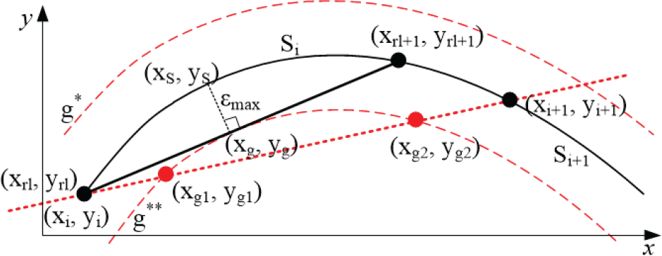
Example of trajectory formation using tangents method
Solving the system of equations the intersection points were calculated (x g ; y g ):
If the number of intersection points exceeds one, the motion trajectory intersects the threshold of coordinates, and it is not the right motion path. Hence, calculating tangent points (x g ; y g ) at marginal coordinates:
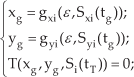
where T – equation of tangent, tT – parameter of coordinates (x g ; y g ) in function S.
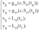
Then calculate the microrobot movement coordinates (xi+1; yi+1) between three points:
After the execution of the control points and the tangents algorithm, motion trajectories are obtained (Figure 11).
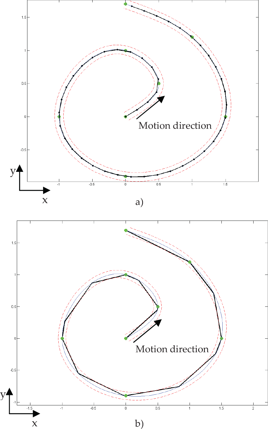
Geometric motion trajectories formed using:a) control points method, b) tangents method
The microrobot behaviour data are calculated after the execution of these algorithms.
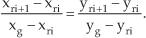
The angle between the motion in a straight line and x-axis is calculated:

Turning angle and turning direction must be determined. Matrix

otherwise D = 2, a microrobot turns counterclockwise

From this matrix, the minimum value of the turning angle
The place of this value in the matrix determines the turn direction (by column number) and which power actuator must be active for it to move on (by row number).
At the calculation of the next moving step, the angle α i is recalculated by the formula:

The differences between these two methods are the length of the displacements and the deflection from the original trajectory (Figure 12).

Deflection from original trajectory dependence on length of displacement
The longer the motion distance, the faster the microrobot can move, but it loses in accuracy.
5. Conclusions
A new design of a mobile microrobot based on standing and travelling waves is proposed in the paper. The mobile microrobot can perform linear motions and rotary motions.
Geometric path-planning algorithms were presented, when different electrode excitation schemes are used. Using geometric path-planning algorithms, the mobile microrobot can follow a trajectory.
The most accurate method for movement along a curve type trajectory is the contact point algorithm, but a microrobot will move slower. The analysis showed that the microrobot would move faster with the tangents method.
Footnotes
6. Acknowledgements
This work was supported by the Research Council of Lithuania (Project No. MIP-075/2012) and the Lithuanian Agency for Science, PiezoPoz (Project Nr.31V-14/12).