
Abstract
This paper deals with Epi.q, a family of mobile robots whose main characteristic is a wheel-legged hybrid locomotion. These multi-purpose robots can be successfully exploited for security and surveillance tasks. The document presents state of the art security robotics, the Epi.q mechanical architecture, the concept behind the robot driving unit, three prototypes and the design of a new one.
Keywords
1. Introduction
The increasing need for security systems for indoor and outdoor environments has stimulated the development of intelligent systems based on mobile sensors.
Actually, most modern video-surveillance systems exploit the combined use of static and mobile cameras. The overall representation of the scene comes from static cameras, while mobile cameras intervene when some anomaly is detected, providing high-resolution images of particular people, vehicles, objects or devices. Therefore, the use of mobile cameras carried by robots expands the potential of a traditional surveillance system, allowing a specific zone to be monitored on-demand. Additionally, a mobile robot can be equipped with additional sensors in order to detect, for example, chemical or radioactive contaminations, avoiding the risks related to direct human intervention. Furthermore, a mobile robot can operate in a specific environment using devices such as robot arms or tools designed in order to accomplish a specific task.
Surveillance robots can also be successfully employed in the military field, such as for patrol or search and rescue tasks. Using mobile robots makes it possible to effectively secure large areas, keeping people out of danger. They can be remotely operated or move autonomously and relay back video images to an operator.
Therefore, robotic solutions for security tasks can greatly improve the safety and security of personnel. These robots must navigate well from asphalt in outdoor urban environments to corridors in buildings, over carpets, or in water, mud, grass and snow. They must be able to overcome both regularly shaped obstacles such as stairs and irregular shaped ones such as rocks, downed trees and other miscellaneous objects.
Looking at mobile robotics, many platforms suitable for security applications can be found. Packbot [1], a tactile mobile robot developed by iRobot, performs dangerous tasks such as surveillance and reconnaissance, inspections or hazardous material detection. It is a tracked robot with “flippers” that enable the robot to climb over obstacles, to self-right itself and to climb stairs, enhancing ability over a simple tracked robot.
Helios IX [2], developed by Hirobot, is a tracked vehicle for search and rescue tasks. Equipped with one arm, Helios IX carries out several tasks, such as handling objects and negotiating stairs.
At the AUSA Winter symposium, March 2007, Elbit Systems unveiled its latest UGV, known as VIPeR. This robot is designed to support infantry forces in combat operations or patrol operations. The Galileo Wheel [3], a patented system developed by Galileo Mobility Instruments ltd that combines wheel and track in a single component, is the most innovative characteristic of the robot. This technology enables the robot to use wheels whenever possible and tracks whenever needed.
RHex [4, 5], developed by the Carnegie Mellon Robotics Institute, is a multi-purpose robot, which can be successfully implemented for security tasks. It is characterized by compliant leg elements that provide dynamically adaptable legs and a mechanically self-stabilized gait. This hexapod robot, cockroach-inspired, uses a simple mechanical design with one actuator per leg and is capable of performing a wide variety of tasks, such as walking, running, leaping over obstacles and climbing stairs. The Loper robot uses a locomotion system similar to the one of RHex, but with a leg shape specially conceived for stair climbing [6].
The Tracker, developed by Engineering Services, is an all-weather, all-terrain, waterproof mobile robot suitable for exploring hostile environments. The ability to reposition its centre of gravity on the move provides increased stability when the robot is ascending or descending stairs, slopes, scaling obstacles, or crossing difficult terrain. Using a remote control it is possible to handle hazardous situations such as collecting real-time, mission-critical reconnaissance information and surveillance footage through a remotely movable camera, detecting and neutralizing dangerous items, such as improvised explosive devices, radioactive materials and hazardous chemicals, or manipulating an unknown package.
In general, as discussed in [7], mobile robots can be classified on the basis of their locomotion system into four main classes: wheeled robots [8-10], tracked robots [11, 12], legged robots [13, 14] and hybrid robots [15-17], which present a various combinations of wheels, tracks and legs.
The authors worked for years on mobile robots, developing a family of mobile hybrid robots called Epi.q, due to the epicyclical gearing housed in the driving unit. These multi-purpose robots can be successfully implemented for security and surveillance tasks.
The article aims to provide an overview about the Epi.q robot family. In Section 2 the mechanical architecture of Epi.q robots is described, three prototypes are presented in Section 3, in Section 4 the experimental characterization of the prototypes is discussed and finally, future works are discussed in Section 5.
2. Mechanical architecture
Epi.q is a family of smart mini robots able to move in structured and unstructured environments, to climb over obstacles and to go up and down stairs. Epi.q robots passively adapt their locomotion from rolling on wheels to stepping on rotating legs, according to ground conditions and obstacle presence, without an active control intervention. Using wheels whenever possible and legs only when needed, their energy demand is very low compared to the energy demand of tracked and legged robots with a similar obstacle-crossing capability.
2.1 Chassis, a modular approach
The chassis architecture can be designed using a modular approach that allows the comparison of several architectures in a systematic way. It consists of grouping the main elements, which can define the robot architecture, combining those elements in order to quickly generate several alternatives and compare the achieved options.
The main features considered in the modular classification, just dealing with the mechanical architecture of the robot, are listed below: traction type (with two or four driving locomotion units), number of traction motors, type of transmission, steering mode, frame structure (with specific reference to its joints) and presence of suspensions. Other aspects can be added to the modular classification so as to define the mechanical architecture of the robot in a more comprehensive mode.
Furthermore the same modular approach can be adopted in order to classify sensors, actuator types, control and navigation systems, optional devices (such as robot arms) and so on, but in this paper we intend to limit the analysis to the mechanical architecture.
The classification thus obtained, summarized in Table 1, is suitable for the organization of an evolutionary process while designing new robot versions. A specific architecture is obtained by combining different features and its acronym is obtained by joining the feature acronyms.
Classification of mechanical architecture features

In regards to the considered alternatives for the transmission system, clarification is shown in Figure 1. The direct transmission through a shaft (ST) is suitable in the case of a direct connection between the locomotion unit and the frame where suspensions are absent (NSU). In the presence of suspensions, it is necessary to adopt a swinging arm, which connects the frame and the locomotion unit. The transmission of the motion can be mainly realized through belts, (BT), conical gears (CT), or cylindrical gears (GT). Different solutions involve different overall sizes and constructive requirements and can be selected on the basis of the required strokes of the employment area and of the available budget.

Epi.q transmission systems
Regarding the suspension system, Figure 2 shows the considered alternatives. In the case of the passive suspension unit (PSU), elastic and damping elements constrain the relative motion between the swinging arm and the robot frame; a simple constructive solution makes use of a pair of toothed wheels joined respectively to the arm and to a torsional elastic/damping element, as shown in Figure 2 on the left. In the case of active suspensions units (ASU) the elastic/damping element is replaced by an actuator, which controls the angular position of the arm; this solution both provides an effective vibration control and allows management of the robot attitude. Actually, by moving the arms, the entire frame can be moved up or down, allowing the robot to improve its step or slope negotiating aptitude and to increase the static stability margin. However, the solution of fully active suspension (ASU) could be too expensive from an energetic point of view and too complicated from a control point of view. Therefore, it might be interesting to estimate alternatives in which the passive elements are used in combination with irreversible actuators (APSU); the passive elements can be dedicated to the passive vibration control, while the actuator can be mainly addressed to the attitude control, as shown on the right in Figure 2. The coupling of passive and active elements can be realized in series (as shown in Figure 2), or in parallel.

Epi.q suspension systems
Figure 3 shows the first proposal for the Epi.q mechanical architecture. It consists of a forecarriage (red), a central body and a rear axle (blue). The forecarriage is composed of a frame, linked to two driving units (2UD), which houses the transmission system and controls the robot locomotion. The driving units are three-legged units with three wheels mounted at the end of each spoke; they are driven by two traction motors (2TM), connected to the locomotion units by means of a shaft (ST). Differential steering (PDS) has been chosen to provide both driving and steering functions. If both the motors, joined to the driving units, are driven in the same direction and speed, the robot goes in a straight line. If one driving unit rotates faster than the other, the robot follows a curved path, turning inward toward the slower driving unit. If one of the driving units is stopped while the other continues to turn, the forecarriage pivots around the stopped driving unit. If the driving units turn at an equal speed but in opposite directions, both driving units traverse a circular path around a point centred half way between the two driving units, therefore the forecarriage pivots around the vertical axis. The rear axle comprises two idle locomotion units. Each unit consists of an idle three-legged unit with three radially located idle wheels. The central body is a platform, which connects the forecarriage and the rear axle, where a payload can be placed. Two passive revolute joints (LJ-VJ), mutually perpendicular, link the front and the rear part of the robot. The vertical joint allows robot steering, while the horizontal joint guarantees correct contact between the wheels and the ground, even without a suspension system (NSU). Therefore, according to the classification, this architecture is called 2UD 2TM ST PDS LJ-VJ NSU. This architecture was implemented in the Epi.q-1 (see Section 3.1) and in the Epi.q-TG FWD (see Section 3.2) robot prototypes.

2UD 2TM ST PDS LJ-VJ NSU architecture
An alternative mechanical architecture is presented in Figure 4, where the rear axle is equipped with a traction motor, connected to the two rear locomotion units through a differential gear and drive shafts. The corresponding acronym is, therefore, 4UD 3TM ST PDS LJ-VJ NSU. This architecture was implemented in the Epi.q-TG AWD robot prototype (see Section 3.3).

4UD 3TM ST PDS LJ-VJ NSU architecture
This new version allows slopes with a greater angle to be traversed and, in general, even better mobility on irregular and uneven terrains can be obtained.
Figure 5 shows an actuated steering (AS) architecture, where a steering actuator is introduced in an articulated frame with a central vertical joint, such as in some types of excavators. The steering actuator controls the relative rotation between the forecarriage and the rear axle and consequently the robot trajectory. In this architecture just one traction motor is connected to the driving units through a differential gear. Its acronym is 2UD 1TM BT AS AVJ PSU.

2UD 1TM BT AS AVJ PSU architecture
It is simple to obtain a version with four driving locomotion units, simply by using a forecarriage and a rear axle with the same architecture, as shown in Figure 6. The architecture acronym is 4UD 2TM BT AS AVJ PSU.
4UD 2TM BT AS AVJ PSU architecture
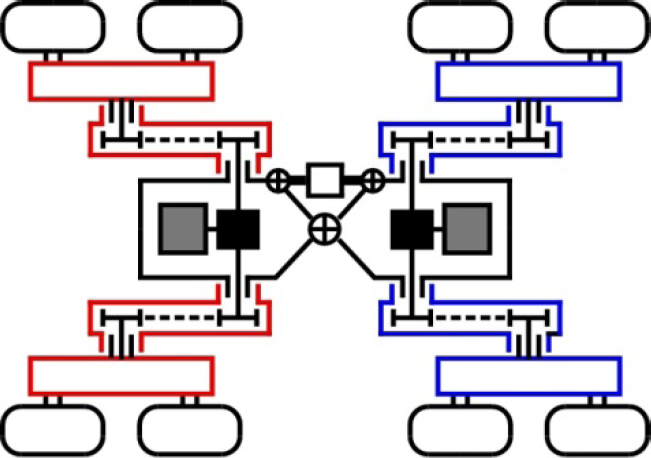
Also in architecture with a central vertical joint, a steering function can be obtained that independently controls the speed of the two front traction motors connected, respectively, to the right and left units, as proposed in Figure 7 for the 4UD version (4UD 3TM BT PDS VJ PSU architecture).

4UD 3TM BT PDS VJ PSU architecture
The schemes of Figures 5-7 are related to robots not equipped with horizontal joints. Therefore, it is necessary to add a suspension system (Figure 8) and a transmission system between the traction motor and the locomotion unit, in order to ensure correct contact between the wheels and the ground.
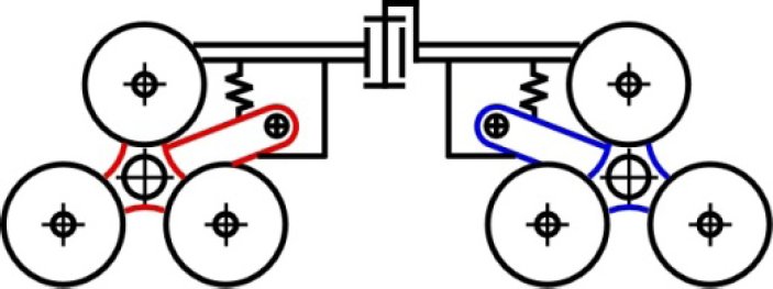
Epi.q architecture with PSU and BT, lateral view
Figure 9 illustrates an architecture with four locomotion units, two traction motors and distribution by differential gears, with actuated steering and a frame articulated through a horizontal joint and a vertical one placed in the central region, and without a suspension system. This solution, classified as 4UD 2TM ST AS LJ-VJ NSU and achievable with minimal costs due to its simplicity, still guarantees optimal mobility on uneven terrain and the possibility of overcoming steps and stairs. The trajectory of the robot can be imposed by a remote control that supplies only two reference signals: the advance speed (proportional to the angular speed of the two traction motors) and the turning radius (handled by the steering actuator).

4UD 2TM ST TS LJ-VJ NSU architecture
This version can be further simplified and lightened by removing one motor and one differential gear, and replacing two driving locomotion units with two idle locomotion units, without the inner transmission system. Obviously this solution shows partially reduced performance in terms of negotiating slopes and unevenness.
Figures 10-11 conclude the outlook of alternative architectures presented in the paper.

4UD 4TM ST TS LJ NSU architecture

4UD 2TM BT TS NJ PSU architecture
Figure 10 illustrates an architecture with a frame articulated through a longitudinal joint, four driving locomotion units and four traction motors. The suspension system is not implemented in this architecture and steering function is obtained such as in tracked vehicles. This solution can be classified as 4UD 4TM ST TS LJ NSU.
Figure 11 proposes the last constructive solution. On each side, the two locomotion units are constrained to only one arm that is connected to the main frame by a revolute joint and two elastic/damping elements. On each side, only one motor drives both the locomotion units. This architecture can be classified as 4UD 2TM BT TS NJ PSU.
Figures 10-11 present two architectures suitable for very simple and sturdy vehicles that in some way have to proceed over any type of terrain, allowing the robot not to stop even in case of overturning and that may be very difficultly arrested.
All the proposed evolutions of the Epi.q robots have a three-legged locomotion unit, thus guaranteeing the robot to advance on wheels or on rotating legs, according to the type of terrain and obstacles.
2.2 Driving unit
The driving unit is the Epi.q main feature. It is a three-legged unit with three radial wheels mounted at the end of each spoke (Fig. 12). It houses the transmission system and controls robot locomotion. If the torque required for moving on wheels exceeds the torque required for moving on legs, the robot changes locomotion accordingly, from rolling on wheels to stepping on legs and vice versa. Thus it is required just one motor per driving unit, both for wheeled and legged locomotion.

Driving unit scheme
The transmission system, differently from other mobile robots with the same stepping triple wheel concept such as Spacecat [18] or MSRox [19], is based on an epicyclical gearing, for example, but not necessarily, the one in Fig. 12, in combination with only one actuator.
Considering an observer placed on the driving unit frame, the transmission system is seen as an ordinary gearing, therefore the gear ratio (with sign) of the driving unit transmission system kts can be easily expressed as follows:

The input shaft angular velocity ωi is linked with both the angular velocity of the driving unit frame Ω and the angular velocity of the wheels ωw by means of the gear ratio (with sign) kts, as expressed in equation 2:

When the robot is moving on wheels (advancing mode) the robot weight and the contact between the wheels and the ground constrains the driving unit angular position, as shown on the left in Figure 13; in particular on flat ground Ω = 0. When the robot bumps against an obstacle, if the local friction between the front wheel and the obstacle stops the rotation of the wheel, the driving unit starts to rotate around the stopped wheel centre (ωi = 0), allowing the robot to climb over the obstacle (automatic climbing mode), as shown in Figure 13 on the right. Further details can be found in [20].

Epi.q in advancing mode, on the left, and in automatic climbing mode, on the right
3. Epi.q prototypes
The Epi.q project aims to design and build small mobile platforms, able to face a structured environment, with flat surfaces and steps, as well as an unstructured one, with uneven ground and obstacles. Up to now three different prototypes have been built and others are under design and/or construction.
The gearing, housed in the robot driving units, controls the locomotion transition, switching from wheeled to legged locomotion depending on obstacle presence and terrain characteristics, without any sensor or control intervention. Using wheels whenever possible and legs when needed, the energy demand is very low, compared to tracked and legged robots with a similar obstacle-crossing capability.
Even if Epi.q robots have features in common, each prototype has peculiarities that influence its performance; the main differences involve the driving unit (gearing and geometry), the frame architecture (location and arrangement of the joints) and the choice between two or four active driving units (FWD, AWD).
3.1 Epi.q-1 prototype
Epi.q-1 (Figure 14) was the first prototype of a mobile robot, designed and built by a team from Politecnico di Torino – Department of Mechanics; the project was part of a scientific research funded by the Italian Ministry of Education, Instruction and Scientific Research.

Epi.q-1 prototype
The Epi.q-1 frame architecture is characterized by two mutually perpendicular revolute joints: the vertical joint enables robot steering, while the horizontal joint assures contact between the wheels and the ground even on a uneven terrains. The two front driving units can be switched from a closed configuration, suitable for motion in narrow spaces, to an open configuration, useful for traversing higher obstacles and vice-versa [21]. Each driving unit is powered by a Solarbotics GM17 gear-motor, declared specifications are a no load angular speed of 60rpm and a maximum torque of almost 1N m, when it is powered at 12V.
According to the nomenclature described in Section 2, it can be classified as 2UD 2TM ST PDS LJ-VJ NSU.
Epi.q-1 weighs approximately 2.6kg and measures 160mm× 360mm× 280mm (height × length × width), with a driving unit that is 125mm high in open configuration and 98mm in closed configuration. The steering angle between the front axes and the central body is limited to a range of ±40°, while the angular excursion between rear axle and central body is limited to ±10°. On flat ground the maximum speed is approximately 0.5m/s.
The human operator controls the robot by means of an Hitec - Laser 4 transmitter and the radio signal is processed by a Sabertooth 2X5 driver that provides the motors with the proper voltage. The power source both for the motor and the electronics is a removable 11 V/2200 mAh battery.
3.2 Epi.q-TG FWD prototype
Epi.q-TG FWD (Front Wheel Drive), the second prototype of the Epi.q family, was designed and built in collaboration with Politecnico di Torino and Università di Genova, see Figure 15 [22].

Epi.q-TG FWD prototype
It can be classified as 2UD 2TM ST PDS LJ-VJ NSU, just like Epi.q-1, nevertheless the overall mechanical design has been refined in order to improve performance and reliability. The Epi.q-TG FWD prototype has a more robust and efficient driving unit, which improves its performance on uneven terrains. Each driving unit is powered by a gear-motor and the declared specifications are a no load angular speed of 81rpm and a maximum torque of almost 0.5N m, when it is powered at 12V. The driving unit ability of changing the configuration has been removed because the related mechanical complexity was not repaid by significant benefits in terms of performance for most applications.
Epi.q-TG FWD weighs approximately 4kg and measures 200mm × 450mm × 280mm (height × length × width), with a driving unit that is 130mm. The steering angle between the forecarriage and the central body is limited to a range of ±55°, while the angular excursion between the rear axle and the central body is limited to a range of ±25°. On flat ground the maximum speed it can reach is almost 1m/s.
The Epi.q-TG FWD prototype, which has the same battery type as Epi.q-1, was tested on a smooth terrain, providing more than four hours of continuous runtime on one charge and up to 6km of travel.
3.3 Epi.q-TG AWD prototype
Epi.q-TG AWD (All Wheel Drive), shown in Figure 16, is an evolution of the Epi.q-TG FWD, which was designed in order to pass from a 2UD to a 4UD robot.

Epi.q-TG AWD prototype

Epi.q Lizard prototype
It has four active driving units: the front driving units have two independent electric motors that allow differential steering, while the rear driving units have two motors coupled to the input shaft of a differential gear. The four gear motors have the same characteristics as the ones used in Epi.q-TG. The overall mechanical design is similar to Epi.q-TG FWD, since only the rear axle has been modified. According to the nomenclature, it can be classified as 4UD 4TM ST PDS LJ-VJ NSU.
The Epi.q-TG AWD weighs around 4.9 kg and is the same size as the Epi.q-TG FWD: 200mm × 450mm × 280mm (height × length × width). Epi.q-TG AWD shows a slightly better performance in comparison to Epi.q-TG FWD for the maximum height of the obstacle it can pass (115mm), due to the push of the rear unit, but the main benefits of the integral traction are in climbing slopes and in moving on uneven and slippery terrains. On flat ground the maximum speed it can reach is almost 1m/s.
4. Characterization of Epi.q prototypes
4.1. Static stability
The stability of a wheeled robot, which is stationary or moving at a constant speed, is expressed in terms of the gravitational stability margin, which is the minimum distance from the robot centre of gravity projected on the ground plane to the edge defined by the contact points of two wheels and the ground. If the robot is driving parallel to a downhill slope, the gravitational stability margin is the margin of longitudinal stability and if it drives along a cross-hill slope (or normal to a downhill) it is the lateral stability margin. The maximum gradeability is defined when the gravitational stability margin is zero and can be estimated from the coordinates of the centre of gravity with respect to the ground and the contact point of the wheels.
Consider Epi.q-1 moving uphill frontwards (or downhill backwards) on a slope, the theoretical maximum value it can drive is limited to 62° when the robot is moving uphill frontwards (or downhill backwards), to 32° when it is moving downhill frontwards (or uphill backwards) and to 59° when it is driving along a cross-hill (or normal to downhill). Therefore, the maximum downhill gradeability is 32°, while the maximum cross-hill gradeability is 59°.
Similarly, the theoretical maximum value Epi.q-TG FWD can drive at is limited to 70° when the robot is moving uphill frontwards (or downhill backwards), to 51° when it is moving downhill frontwards (or uphill backwards) and to 60° when it is driving along a cross-hill (or normal to downhill). Therefore, the maximum downhill gradeability is 51°, while the maximum cross-hill gradeability is 60°.
With regards to the Epi.q-TG AWD, it theoretically can drive on 58° slopes when the robot is moving uphill frontwards (or downhill backwards), 56° when it is moving downhill frontwards (or uphill backwards), and 50° when it is driving along a cross-hill (or normal to downhill). Therefore, the maximum downhill gradeability is 56°, while the maximum cross-hill gradeability is 50°.
4.2. Step negotiating aptitude
The purpose of the test is to assess the ability of Epi.q robots to negotiate obstacles, which are different in height. The robots are driven close to a step, on a flat surface, at low speed.
Epi.q-1 can negotiate steps up to 90mm high, equivalent to 72% of the driving unit height. In case of a collision between the driving unit frame and an obstacle, the robot can climb with a slightly irregular motion, combining the advancing mode and the automatic climbing mode.
The maximum step Epi.q-TG FWD can climb over is 110mm high, equal to 84% of the driving unit height. The risk of interference between the driving unit frame and obstacles is smaller, due to the new design of the driving unit.
Epi.q-TG AWD can climb over even higher obstacles due to the pushing action of the rear unit. The maximum step it can negotiate is 115mm high, which is 88% of the driving unit height.
4.3. Slope negotiating aptitude
The aim of the test is to assess Epi.q robots' ability to move on inclined surfaces. The robots were driven up a ramp.
The experimental tests have shown that, when Epi.q-1 is moving on an inclined surface with the driving unit in open configuration, a 13% slope triggers the transition between advancing mode and automatic climbing mode; while, in the case of a closed configuration, a 9.5% slope triggers the transition. The robot was tested on different surfaces with an increasing friction coefficient. Moving on plywood the wheels never skid and the maximum slope it can reach is 45%, due to motor torque limitations.
Epi.q-TG FWD tests have shown that the locomotion transition is triggered by a 31% slope. In the experimental campaign the Epi.q-TG FWD prototype was tested on slopes of up to 33%, with wheel-ground friction coefficient μs = 0.83. Obviously, when the maximum slope is limited by the friction coefficient, the traction wheels can start skidding without reaching the transition condition.
The experimental tests have shown that Epi.q-TG AWD can negotiate inclined surfaces up to 40% with the same wheel-ground friction.
4.4. Performance comparison
In Table 2 the performance of the existing three Epi.q prototypes is compared. All of them were tested using a wooden structure varnished with sanded paint to grant μs = 0.83, allowing variable step height and slopes.
Comparison of the three prototypes

5. Future works: Epi.q Lizard
Currently in the design phase, Epi.q Lizard is the last version of the Epi.q family; it should increase robot mobility on irregular and uneven terrains in comparison to previous prototypes [20, 21, 22]. According to Section 2, it can be classified as 4UD 4TM CT TS LJ-ATJ NSU.
The robot is mainly composed of two frame modules, linked by means of a passive longitudinal revolute joint (f) that allows the robot to adapt to ground unevenness.
Each module houses: two motors (b) to independently control the driving units (a), two bevel gearings (c) that connect the motors with the driving units, a micro-board for motor control, a transmitter for remote communication and a battery pack for module powering (d). One or both the modules can additionally house a Wi-Fi camera (e) for remote control and/or to relay back video images to an operator. Two actuators (g) control robot configuration, by means of a relative rotation of the two modules around a transversal axis. Therefore, the risk of interference between the robot body and an obstacle has been reduced, as shown in Figure 18 and the robot can climb over higher obstacles.

Epi.q Lizard facing a step
The mechanical architecture of the Epi.q Lizard lowers the robot centre of gravity, with respect to previous Epi.q versions, allowing the robot to negotiate steeper slopes. While going up a slope the rear axle becomes more loaded than the front axle and the difference between the rear axle load and the front axle load is higher if the robot centre of mass is higher. Therefore, with a low overall centre of mass, traction is more distributed and effective.
Moreover, the proposed design allows the robot to properly work in case of it tipping over.
Thanks to the modular conception, the robot can be quickly modified on the basis of the task specifications.
6. Conclusions
The presented family of mobile robots shows the benefits in the design phase due to the proposed modular approach. Starting from a common locomotion unit (which can be realized in different sizes to fulfil the requirements of a wide range of applications) it is possible to compose several different architectures, with different levels of mechanical and control complexity and peculiar characteristics.
The modular classification discussed in Section 2 offers a comprehensive outlook of possible design alternatives, considering that any arrangement is not better than the others in any condition, but only with specific operative requirements.
For example, if traction on uneven terrain is a priority, suitable layouts include four active locomotion modules (for example Epi.q-TG AWD, 4UD 4TM ST PDS LJ-VJ J NSU), if the task involves only operation in indoor environments with stairs, a front wheel drive version is sufficient (for example Epi.q-TG FWD, 2UD 2TM ST PDS LJ-VJ NSU), if the objective is the ability to move even after an overturn, the Epi.q Lizard scheme (4UD 4TM CT TS LJ-ATJ NSU) is adequate.
Moreover, Epi.q Lizard can be equipped with an actuator that can bend its body to negotiate steps, while in an outdoor unstructured environment without stairs the simplest version without bending capability may be preferred for simplicity, economy and light weight figures.
Thanks to the modular approach in mobile robotics, it is possible to select the most convenient layout consistent with the operative requirements with useful benefits in terms of mean time to repair; this is of utmost importance, for example, in a future security scenario based on surveillance robots which operate in a coordinated manner under the supervision of a cognitive system.