
Abstract
A significant number of individuals with severe motor impairments are unable to control their wheelchair using a standard joystick. Even when they can facilitate the control input, navigation in a confined space or crowded environments is still a great challenge. Here we propose a wheelchair framework that enables the user to issue the command via a multi-input hands free interface (HFI), which subsequently assists him/her to overcome difficult circumstances using a multimodal control strategy. Initially the HFI inputs are analysed to infer the desired control mode and the user command. Then environmental information is perceived using a combination of laser and Kinect sensors for determining all possible obstacle locations and outputting a safety map around the wheelchair's vicinity. Eventually, the user's command is validated with the safety map to moderate the final motion, which is collision free and the best for the user's preference. The proposed method can reduce the burden of severe impairment users when controlling wheelchairs by continuously monitoring the surroundings and can make them move easily according to the users' intention.
1. Introduction
In recent years, numerous methods have been introduced for developing smart robotic wheelchairs to accommodate disabled people, as reported by Simpson [1]. The development trend can be broadly divided into three main areas [2]: 1) Improvements to assistive technology mechanics, 2) Improvements to the user-machine physical interface, 3) Improvements to shared control between the user and the machine. One of the key aspects of smart robotic wheelchairs is to provide independent mobility for users with severe impairments who cannot control the wheelchair by means of a standard joystick. This may be due to several reasons, such as cerebral palsy or cognitive impairment [3]. It has been reported that people with mobility difficulties tend to be more depressed or anxious compared to normal people [4]. Therefore, recovering their mobility may significantly improve their quality of life.
Generally, the devised smart wheelchair platform is highly dependent on the user's profile [5] (i.e., abilities and disabilities) and there is no single solution that is suitable for all users. Based on the knowledge about what type of input medium that the users can operate, we can gain insight about the appropriate level of assistance. Users with severe motor impairment (e.g., spinal cord injury) generally lack muscle control and in the worst cases they are unable to control the movement of arms and legs. Input devices based on cues or actions generated from the head (e.g., facial, brain, gaze, tongue and bite) can be possible media for such users at all levels of injury [6]. As the level of injury increases, generally the users are unable to steadily move their hand. Therefore, they need to rely on an alternative medium. Such a medium should provide the users with the ability to control the direction in which they move (i.e., left, right, forward and reverse) and to initiate/terminate the movement.
Voice-activated navigation [7] requires quiet ambience and may not be good for use in busy and noisy environments. Furthermore, it is not well mannered and it is sometimes considered impolite to talk aloud in a silent area. As for brain waves [8], recently they have become a subject of interest in controlling machines. To do so, electroencephalography (EEG) signal patterns need to be classified and grouped into intended actions. The user must have good emotional control and concentration for effective control. This is a burden on the user, although this medium may be a good alternative for people with a totally paralysed body. Gaze input offers good information, such as head [9] and eyes [10] direction for manipulation. The basic idea is that an area at which the user gazes represents the intended direction, which imitates human physiological behaviour while walking [11] or driving. Although this medium seems a good candidate, it is hard to distinguish actions for steering the wheelchair from simply looking around. Therefore users have to concentrate when they navigate and give up viewing surroundings.
Perhaps the best solution to solve the trade-off between being easy to use and reliable is to adopt the multi-input approach [12, 13]. In this approach, multiple users' cues are analysed before issuing control commands. This can be compared to how we drive a car. We use the hands to control the direction, while using the legs to control the acceleration. Using this strategy, we can assign different user's inputs (e.g., direction to move using gaze and initiate/terminate movement using a switch) to different tasks and hence will impose fewer burdens on the user compared to a method that solely relies on a single input.
According to Fehr et al. [14], among 200 practicing clinicians in the U.S., 40% of their patients found it hard or impossible to control their wheelchair by using a standard joystick or alternative devices. More recently, it has also been reported by Wan et al. [15] that most patients with motor impairment are unable to steer their wheelchair when avoiding obstacles or do parallel parking by using a joystick. These clinical findings provide us with insights into the importance of devising a computer-controlled platform to assist the users by reducing their workload and increasing safety. In this framework, the user input, along with environmental information, will be seamlessly analysed for providing necessary assistive tasks. The amount of given assistance usually varies depending on how severe the users' impairments are and the assistance can be categorized into three main levels: shared-control, semi-autonomous control and autonomous control [16]. The level of given assistance should be decided by maximising the user control ability and the computer only assists the user incapability side [5].
The shared-control mode basically lets the user operate the wheelchair; the computer only steps in when it is absolutely necessary (e.g., when passing through a door or avoiding an obstacle) [17, 18]. The autonomous control mode, on the other hand, lets the wheelchair move automatically in known environments to a final destination pre-selected by the user [19]. Due to this nature, shared-control is suitable for assisting a user who can provide continuous input commands and autonomous control is more adequate for a user who is unable to provide low level orders, who gets fatigued easily, or who has visual impairment [3]. The semi-autonomous control mode lies in between both control modes, in a sense that the computer performs short-term route planning and reactively avoids obstacles and the user only intervenes when they wish to deviate from the plan [20][21]. Once a command is issued, the users can relax while the computer is completing the task. Unlike autonomous control, semi-autonomous control does not need an actual map of the environment; only a local safety map is required, which gives the user freedom to move in new environments.
In this paper we propose a method for enhancing wheelchair manoeuvrability for severe impairment users. It consists of two main modules: the alternative hybrid input interface and semi-autonomous driving assistance. The former is for enabling the user to issue control commands easily, while the latter is for assisting the user's mobility in difficult situations. Since reliable and accurate information on the environment is crucial for safe navigation, a multisensory fusion approach is used to perceive the surrounding information and subsequently detect potential obstacle locations. Integration of the user's inputs along with the environmental inputs is provided for the computer to determine a motion that follows the user's preference while avoiding any possible threat. With such a setup, the wheelchair can effectively overcome dangerous situations, while the user can still drive the wheelchair by himself/herself.
2. System Overview
The developed wheelchair system is controlled by both the user and a computer. When the user takes control, the computer will assist this by overriding any command that may cause a collision. On the other hand, when the computer performs an autonomous task, the user, if she/he wishes, can choose a different direction to avoid obstacles or refine the heading direction during seeking a goal. In the system, the user assigns the goal information by looking at the intended destination area. As a result, the planner only knows the direction to go, but not an exact destination location. We assume that the wheelchair is driven by a sighted user who can assist the high-level navigation, especially when going to the final location. Due to this assumption, the planner does not need to lead the wheelchair to the goal location automatically.
The system is implemented on an electric wheelchair (TT-Joy, Matsunaga Corp.) equipped with a standard computer and a collection of sensors. The sensors are responsible for inferring the user input and monitoring the environments. They consist of a switch, a standard webcam (Logicool), an RGBD Camera (Kinect, Microsoft), a laser range finder (UTM-04LX, Hokuyo Electric Machinery) and an Inertial Measurement Unit sensor (VN-100, Vectornav) as shown in Figure 1. The general method pipeline is illustrated in Figure 2. Basically, it contains three main components: 1) Human Computer Interfacing (HCI), 2) Environments monitoring, 3) Computer for blending information from the HCI and the safety map to provide the final optimal motion.

Sensors arrangement
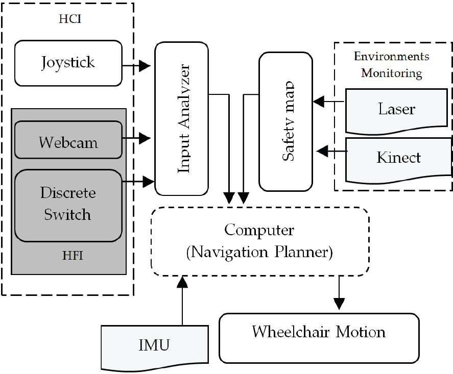
General operation flow
The first wheelchair input comes from a joystick, which is a standard HCI tool. When the user can operate this device, it is enough to consider only shared-control assistance. However, the focus here is on the second HCI that we call a hands-free interface (HFI). It consists of a switch and a webcam for receiving the user's commands. The former is responsible for initiating/terminating several manoeuvring modes, while the latter provides the direction to move in.
For the environments monitoring component, the combination of a laser range sensor and a Kinect is used to sense the environment for potential obstacles and deliver a safety map to the computer. The laser sensor is located in the front part of the wheelchair at a height of 20cm above the ground, covering an angle of 270°. The Kinect on the other hand is installed 1.3m above the ground and can perceive 3D information within 57° X 43° of the angle view. Before using both sensors, a calibration is performed to ensure the reliability of the obtained data. We used the standard stereo calibration procedure for the Kinect and the linear calibration model for tailoring data from the Kinect and the laser. The IMU sensor provides information about the wheelchair's current state in the world and is mainly employed here for correcting the heading orientation. Output from this sensor is calibrated and errors are compensated for using the extended Kalman filter. Therefore, the output provides a reliable 6 DOF reading.
During full time operation we do not directly use the HFI to continuously control the wheelchair, instead we only use it for heading the wheelchair in the user's intended direction in the manual mode. In the developed system, the computer mainly takes over the responsibilities for navigation and low-level control, while the user only takes care of the general directions of travel. This results in low user involvement and therefore higher user comfort. During semi-autonomous control, if the user wants to stop or deviate from the planned path, she/he can always interrupt by pressing the switch.
Figure 3 illustrates how the proposed system can give assistance. In this example the user wants to move from the current position to the goal location. Initially she/he manually alters the heading to face the goal. When semi-autonomous control is activated, the wheelchair moves to the desired direction, avoiding obstacles and refining the orientation when necessary. Due to a series of such operations, the final heading may divert from the goal direction. In such cases, the user can manually steer until the wheelchair reaches the goal. If no obstacles appear during travelling, the wheelchair just moves straight to the goal location.

Illustration how the proposed system can assist the user in practical operation.
We tune the input systems in this way because HFI offers few distinct commands and sometime contains errors during the obtaining process; therefore solely relying on such a medium may sometimes lead to an inappropriate motion command. Furthermore, unlike the joystick, the HFI requires more concentration from the user. Consequently, for a longer operation, it may become a burden on him/her and she/he cannot enjoy the surroundings while manoeuvring.
3. Hands-free Interface (HFI) and Input Analyser
A conventional joystick is well known for its functionality and for controlling the wheelchair effectively. Therefore, when users are unable to use this medium, the best alternative should be able to imitate the joystick operation. It should be easily adapted to the user and minimize the user's workload. The HFI uses a switch to initiate and terminate movement and natural gaze to instruct the direction of movement. With such a setup, the gaze actions, which are intended to steer the wheelchair can be distinguished from just looking around by the central controller.
The switch is a single and momentary type and is responsible for triggering several manoeuvring modes (i.e., “stop”, “semi-autonomous” and “manual”) depending on how long the user leaves it “on”. It can be realized by various mediums, such as detecting motion of facial parts (e.g., eye blinking or shaking), voices or a button switch. Physiological features will impose many burdens on the user when she/he needs to issue a command frequently, especially when she/he navigates in a limited space. Therefore, we choose to use a simple bitelike switch button (i.e., not an actual bite switch but one that we created by imitating the nature of the switch operation).
When the switch receives a cycle of momentary pattern (low→high→low), the “stop” or “semi-auto” command is executed depending on the current state (i.e., when the current state is stop, the system turns into semi-auto and when the current state is semi-auto, the system turns into stop). When it continuously receives a high signal, the system enters the “manual” mode until a low signal is issued. Every time the user exits the manual mode, the system stops and waits for the next command. In the manual mode, gaze direction is used to steer the wheelchair until it reaches the desired direction, while in the semi-auto mode gaze is only considered during initializing the goal direction and during performing an avoiding action.
For obtaining the gaze data, we use FaceAPI software [22], which can supply such information in real time. Figure 4 shows an example of the inferred gaze where the yaw angle is denoted by αu, the pitch by βu and the wheelchair orientation by θwchr. In this work, the yaw angle differentiates between “forward”, “left” and “right” movements, while the pitch angle distinguishes “reverse” movement. To determine the angle threshold values for characterizing the movements, we recorded the values of αu, βu and θwchr when the user manually steered the wheelchair using a joystick, in the environment illustrated in Figure 5 (Top). The obtained pattern is given in Figure 5 (Bottom).

Gaze and wheelchair directions.

(Top) Manual driving route. (Bottom) Measured head direction and wheelchair orientation.
From the pattern, we can see that during straight movement, αu varies between −15° and 15° and at the turnover points the value slightly diverts from this range. As for βu, throughout the process it fluctuates between 6° and 55°. Based on the results, we empirically classify αu into three possible movements: {αu ≥ 15° = “turn right”}, {αu ≤ −15° = “turn left”} and {-15° < αu <15° = “move forward”}. βu, on the other hand, will ignite the reverse movement when βu < 6° (i.e., full swing down).
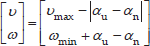
Based on the information from the switch and the gaze direction, the input analyser module decides the control command sent to the central controller. Figure 6 illustrates the mapping. When the switch triggers the “manual” mode, the gaze command is fully executed if this will not cause collision. Depending on the user's ability, the gaze input is treated as a proportional command or a discrete command. For the former command, the wheelchair motion is generated according to Equation (1), where

Control command execution based on the input from the switch and gaze. The shaded area indicates that gaze action will be executed.
When the switch ignites the “semi-auto” mode, the gaze information is only considered during initializing the goal direction and avoiding collision. Except in both situations, the gaze direction does not cause any effect on the wheelchair's motion. This can give freedom to the user to enjoy the surroundings while navigating. For initializing the goal, the user just needs to look at the area where she/he would like to go and presses the switch. The direction where the user looks is then regarded as the goal direction. During obstacle avoidance, the gaze direction is also used to determine the paths to be avoided. The process is almost the same as in the manual control; the only difference is that the user does not need to press the switch. The area that the user looks at during obstacle avoidance is automatically assigned as the direction to avoid if it is collision free.
4. Safety Map Development
In the developed system, the top priority is user safety and hence, a safety map is supplied in all operating modes to ensure that any generated motion is free from collision. In the semi-autonomous mode, the map gives the guidance to generate the optimal motion while seeking the goal or avoiding obstacles. In the manual mode, on the other hand, the map helps the user to brake when the given command is subject to collision.
Basically the safety map is represented by a 2D grid that surrounds the wheelchair with 8 × 8 m2 dimensions as shown in Figure 7 (a). The map indicates traversable surfaces in the environment. Each cell in the map encodes the certainty about the presence of obstacles around the cell. When driving in indoor environments, various potential obstacles exist. In general, obstacles can be classified into three categories: positive (e.g., human), negative (e.g., a downward stairway) and overhanging (e.g., a table) obstacles. Positive obstacles refer to objects that extend up from the ground, while negative obstacles are drastic drop offs in the ground plane. Overhanging obstacles are defined as any objects located above the ground.

(a) Overlapping data overview sourcing from the laser and Kinect. (b) Sample of acquired data: RGB image on the left side and the safety map on the right side.
To ensure the maximum reliability of the safety map, we make use of a combination of a laser sensor and a Kinect camera. The former is used for perceiving positive obstacle placement at 20cm above the ground, while the latter is utilized for detecting all types of obstacles (i.e., positive, negative and overhanging). Both sensors complement each other, in a sense that the laser sensor has a wide field of view (FOV) but is unable to precisely portray the surroundings. On the other hand, although the Kinect has a small FOV, it can recover 3D information.
4.1 Kinect and Laser Sensor Calibration
In order to perform reasoning about RGB pixel placement in 3D world coordinates, we make use of depth data supplied from the RGBD camera Kinect. Since the focal points of both colour and range cameras are located in different axes, we need calibration beforehand to rectify the camera parallax. Details about the calibration process can be found in [23]. In short, the process estimates intrinsic (Im) and distortion (Kn) parameters for both RGB (IRGB) and IR (IDepth) cameras and determines the transformation matrix (E) that maps pixels between them using Equation (2).

The distortion parameters Kn are used for correcting the image through the nonlinear inverse distortion model. A common equation for performing such an operation is given by Equation (3), where x and y are the corrected pixel locations, xw and yw are the original pixel locations in the world coordinates and r2 =xw2+ yw2.

Once the Kinect is fully calibrated, we can easily determine any RGB pixel location in the depth image and vice versa using the simple linear transformation model. Since the Kinect and the laser sensors are also located in different axes, we calibrate both data by minimizing the reading error in each Kinect's FOV angles. The calibration process makes use of the Kinect as the reference axis to deliver the laser sensor data for forming the safety map. Each intersection point between both sensors is collected and used to calculate the transformation model. Empirically we found that the linear model is sufficient to attain highly precise fitted data with a low computational complexity. Figure 7 (b) shows a sample of the obtained information, consisting of a RGB image (left) and a safety map (right). In the safety map, we can see that, once calibrated, the integrated data (the Kinect in grey and the laser sensor in red) are precisely aligned.
4.2 Obstacle Detection via Kinect
With vast amount of data (e.g., colour, texture, pattern), we use the Kinect for classifying the positive obstacle types as human or non-human and identifying the threat area that cannot be sensed directly by the laser sensor (e.g., negative obstacles). The Kinect is fully calibrated and is tilted downwards to obtain more views of the ground plane. To get insight of a hazardous location, the ground plane (Figure 8) must be detected first. We model the ground plane using the following equation:

Geometry of ground plane and negative obstacle detection.
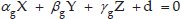
where
Once the ground plane is known, the positional relation between the ground plane and any arbitrary point viewed from the camera coordinate,


Sample of the detected ground plane
4.3 Positive Obstacle Classification
For each positive obstacle, we further classify it as human/non-human by using multi-features and a coarse to fine searching strategy [24]. In short, the process examines the obstacle dimensions on a X-Z plane and removes non-standardized regions with respect to the human dimensions by blob analysis. The pre-validated regions are then mapped onto the X-Y plane of the RGB image and the Depth image to refine the search. In this plane, the human-like regions are further post-validated by using human silhouette information with HU moment features [25]. Eventually, only the surviving areas are fed to the final filter, which is a head detector based on the framework from [26]. Only when any obstacle region passes through all the steps, do we regard the obstacle as a human.
If the obstacle is a human, the wheelchair should approach him/her by respecting the human's personal space [27] to produce a safe and comfortable motion. Considering this, it refrains from for selecting a path in the middle of two people or moving too close to a human. Such situations will most likely occur when operating in the semi-autonomous mode. We build the human encounter module based on the work by Tomari et al. [28]. The system generates a socially acceptable wheelchair motion by modifying the Proxemics rule [29]. Based on the head detector output, the head pose is probabilistically estimated by the particle filter (PF) framework. Assimilation between the head detector and the tracker is achieved via the nearest neighbour data association strategy. The likelihood of ith particle is computed by Equation (6), where Ofi is the average optical flow for 8 points distributed evenly within

The confidence level of each hypothesis is evaluated by computing its weight. We use two evaluation methods based on the image contour and the seven Adaboost cascades for classifying frontal, left and right [30]. The overall weight of each particle is computed by fusing the likelihoods from the image contour and the cascades classifier. Eventually, the current state of each target is estimated by using the average weight of all PF samples.
Once the head pose is known, the personal space shape (illustrated in Figure 10 (a)) is decided according to Equation (7) where (xw, zw) are the centres of two semi-ellipses, α is the yaw head pose angle obtained from the tracker and a and b are the minimum and maximum axes lengths. The first semi-ellipse (circle) (from 180° to 360°) will cover the human's backside area and the minor and major axes are defined by a (we set the value = 0.4 m). On the other hand, for the second semi-ellipse (from 0° to 180°), since it is the human's frontal space, the minor axis is equal to a, while the major axis b may change depending on the situation. b is set at 0.8m when the human is not aware of the wheelchair and 0.4m when the human is aware of it. Figure 10 (b) shows how the personal space is generated depending on whether the human is aware of the wheelchair (bottom) or not (top).

(a) Personal space (PS) shape model. (b) Visualization of the PS's shape evolving (denoted by the red marker) when the head is rotating to the left (top) and front (bottom).

During navigation, the wheelchair regards the personal space zone as a non-trespassing area. Although this restricts the area where the wheelchair can move, from a social viewpoint, this is comfortable for humans.
4.4 Negative Obstacle
Negative obstacles may be more hazardous than positive obstacles because they may make the wheelchair roll or tip over. Negative obstacle regions can be determined based on the height of each point (i.e.,

Negative obstacle region (red colour) in the RGB image and the safety map before (top) and after (bottom) projected onto the virtual ground plane.
To overcome this issue, we define a virtual ground plane. The plane is located at the same level as the actual ground plane and covers the negative region. Each negative obstacle point (Pc) is projected onto this plane to determine the corresponding point (Pc0) (See Figure 8). This relation can be represented by Pc0= Pc
4.5 Overhanging Obstacle
Overhanging obstacles can be regarded as positive obstacles that consist of two parts: the base and the cover. The cover predominates in overall size. The base is explicitly a threat while the cover may be safe or dangerous depending on its location with respect to the ground plane. For example, a table can be classified as a dangerous overhanging obstacle since generally the tabletop will be located around 0.75m above the ground. In contrast, a concrete beam or a ceiling is a safe overhanging obstacle because naturally its location is more than 2m above the ground. In the developed system, we discriminate between safe/unsafe overhanging obstacles based on how high their ‘covers’ are. A safe ‘cover’ will be removed from the safety map, while an unsafe one is treated like a positive obstacle.
5. Navigation using the Safety Map and HFI Input
To detect the optimal traversable regions on the safety map, we adopt an extension of a Vector Field Histogram (VFH+) [31] with a slight modification for considering the HFI input. Traversable regions are defined as the areas on the ground plane that do not pose any threat. VFH will mainly blend the information from the safety map and the HFI input for suggesting the optimal motion of travel. We call cells in the safety map that may contain obstacles active cells. All active cells are transformed into the 1D representation known as Polar Obstacle Density (POD). POD(wi,j) is the value for an active cell (i, j) in the POD representation, which is given by Equation (8), where (xi,j, yi,j) is the coordinate of the obstacle,P0 = (x0,y0) is the centre coordinate of the safety map, ci,j is the certainty value of the obstacle in the cell (in our case is equal to 1), di,j is the distance to the obstacle from P0 and a and b are design parameters.

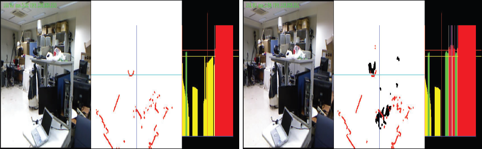
We convert this POD into a binary representation (PODb) where each direction is classified as either 0 (no threat, the wheelchair can move in that direction) or 1 (threat, it should not move in that direction). To do so, we define two values, τc and τd (τd > τc). The former is used for discriminating high and low POD values and the latter is used for determining high-risk obstacle (HRO) locations. A sample of the generated POD is given in Figure 12, where the RGB image, the safety map and the POD distribution image are shown from left to right. In the POD image, the yellow and green bars represent the low and high POD regions, respectively, while the red bars show HRO locations.
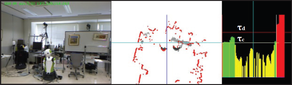
System monitoring view: (left) RGB Image. (middle) safety map. (right) POD distribution image
During straight movement, obstacles to the right and left sides of the wheelchair do not explicitly affect the movement. However, when the wheelchair needs to initiate avoiding actions, such obstacles may become dangerous. In Figure 13, two people, O1 and O2, may block the wheelchair movement. In this scenario, opening V1 meets a condition to be selected and movement to the left is suggested. However, if the wheelchair continues such an action, clearly it will bump into O1 even though the wide opening is available. To overcome such an issue, we generate the PODb as described below and use it to determine the wheelchair motion. Initially, values of all directions in PODb are set as 0. Then we search for HRO locations in the POD. If any HRO is located on the left side or right side of the centre of the POD, all PODb values to the left of the HRO location or to the right of HRO location are set as 1. If there exists no HRO, PODb(ωi,j) is set as 1 if the POD (ωi,j)>τc.

High risk obstacle encountering situation
When HRO is found in the centre of the POD, all PODb values to the left and to the right of this HRO are set as 1 and hence, the wheelchair stops moving. Once all direction values in the PODb locations are annotated, to determine the steering angle, we analyse the best opening in PODb, which must be wide and safe (i.e., Vwide). Also, it must consider the HFI input before sending a signal to the wheelchair. For these reasons, we use a hierarchical strategy and setup a prioritized framework for selecting the future direction according to the goal, the user's intention via HFI and safety.
If the goal angle is found in the wide opening, as seen in Figure 14(a), then it is selected as satisfying the goal-oriented requirement. Note that, the goal direction can always be set and reset by the user at any time by using the HFI as explained previously. When the goal requirement cannot be satisfied, i.e., when the goal is blocked, the wheelchair turns on the collision/obstacle avoidance mode. In this situation, the next priority for selecting a candidate is based on the user's gaze direction (under this mode the user does not have to press the switch). Considering this, when the wheelchair is at the hallway T-intersection (Figure 14 (b)), it can instantaneously steer to the user-driven direction. However when the user points at a direction that is subject to a collision, as shown in Figure 14 (c), the wheelchair neglects the gaze direction and steers to the safest zone. On reaching the zone, the wheelchair then fixes its orientation towards the goal.

Possible of occurrences during navigating (a) Free manoeuvre (b) hallway T-intersection. (c) Avoiding obstacle.
However, if the user presses the switch button while navigating (i.e., enters manual mode), the VFH algorithm still assists the user in such a way that it terminates any user command that may hurt him/her. For example, as seen in Figure 14 (c), if the user commands the wheelchair to the right, since it is dangerous, the computer overrides its command and causes the wheelchair to brake. However in this mode, it does not steer away as in the semi-auto mode; instead it remains stopped and only resumes if the user issues a safe command.
6. Experimental Results
In this section, we analysed the system performance in real operation environments. The evaluation framework consisted of three different parts. First we investigated the feasibility of the designed HFI for manoeuvring the wheelchair in a confined space. Second we measured the accuracy of the constructed safety map in terms of data integration and successful threat annotation. Finally we evaluated the performance of the controller considering both HFI and the safety map.
6.1 HFI Evaluation
In the first part of the evaluation, the user drove the wheelchair in the narrow lab environments illustrated in Figure 15 from a starting point to an ending point marked by ‘X’ using the HFI. In order to complete the task, the subject had to go through a tight space and needed to perform a series of minor and major turns. For the sake of comparison, the user was also asked to navigate through the same environments by using a standard joystick. Each process was repeated five times to determine the input controller precision (T1 to T5).

Sample of commanded path using joystick and HFI.
The resultant wheelchair motions (i.e., the orientation value) for each trial are shown in Figure 16. We can see that by using a joystick the generated motion looks smooth and consistent in terms of repetition. On the other hand, when using the HFI, although some small oscillations are found in the movement, overall we can see that the produced motion is most likely the same as the joystick. This indicates that, this medium can enable the user to command the wheelchair smoothly and is a reliable alternative when the joystick cannot be used.

Recorded wheelchair's orientation when navigate in the environments using joystick (top) and HFI (bottom).
In terms of task completion time, as shown in Figure 17, the joystick yielded the fastest result, with an average time of 37.92s. The HFI required almost double the joystick's time, with an average of 78.2s. This situation happens because of several reasons, such as failure to obtain gaze data or a delay during the communication of data. Therefore, further improvement needs to be devised in the gazing–inference medium, such as using IMU or using an electromyography device. As for the distance of travel, generally there were no significant differences between both mediums (the average for the joystick=14.593m and for HFI =14.506m). In short, it shows that the HFI can work as well as the joystick in terms of the generated motion and the distance of travel. However, regarding the execution time, more work needs to be done to lessen the delay during inferring the gaze information, such as by improving the hardware

Time and distance of travel when using joystick and HFI for five trials of navigation.
6.2 Safety Map Evaluation
In the second part of the evaluation we investigate the feasibility of the safety map for detecting and annotating all types of obstacles (positive, negative and overhanging). Initially we determine the sensor's data integration accuracy, following by a discussion on the performance in each safety map component.
6.2.1 Data Fitting Error between Kinect and Laser
We evaluated the accuracy of the data integration between the Kinect and the laser sensor by computing the difference between readings when measuring the distance to the same object. The data were mainly taken from wall surfaces, since we want both sensors to perceive information on the objects. They were measured at several distances ranging from 1m to 5m to portray the data fitting error globally.
Figure 18 displays the error pattern consisting of 812 measurements. We can observe from this figure that mainly the error becomes significant at FOV angles between 57° to 59° and 120° to 122°, in the range of 4m to 5m. Within this range, the difference in readings between the Kinect and the laser sensor is less than ± 7.12cm. Such precision is sufficient for our need, since most of the time the wheelchair will face threats that are quite significant in size.

Errors pattern between camera points and laser points from varying distances reading in the range of 1m to 5m
6.2.2 Human Cue Detection from the Positive Obstacle
While the ability to detect positive obstacles is essential for generating safe motion, further classification of the obstacle between human/non-human can ensure the final motion will be comfortable for the people in the surrounding area. We measured the performance of the human detector and pose estimator module on five different scenarios (two in a laboratory and three in the hallway).
Figure 19 summarizes the results. It can be seen that, when in the lab environments, under good lighting conditions, the module is able to gain high performance in terms of human head detection (average of 90%) and pose tracking (average of 82%). While, in the hallway, with natural light exposure, the module performance is quite fair, with an average of 70% for head detection and an average of 60% for tracking poses. This is due to the fact that low light exposure does not generate head texture well and hence, prevents the system from accomplishing tasks accurately. However, the module exhibits low false positive error (false alarm) rates in all given situations with the help of a coarse to fine searching strategy. For the overall score, we obtained an average of 82% for correct head localization, with 2.5% false alarms and 73.4% for correct head orientation estimation.

Performance of the head detector and pose tracker in five different scenarios.
When the obstacle is successfully distinguished and the human's pose is correctly estimated, the wheelchair will execute a safe and comfortable motion. If this is not the case then only a safe motion is considered.
6.2.3 Negative Obstacle Range Measurement
We examined whether or not the system can detect negative objects with sufficient precision at the proper times. It is important for the planner to know such information to issue commands that can prevent the wheelchair from falling down by avoiding negative obstacles well in advance.
Figure 20 shows an experimental result of negative object distance measurement. The horizontal axis indicates the actual distance from the front tip of the wheelchair to the negative obstacle (downward stairs with an 18cm stair step in this experiment) and the vertical axis indicates the measured result. It is seen that, at a range from 3m to 1.5m, the measured distance is accurate up to ±7.8cm. As the wheelchair approaches closer, the wheelchair missed the dip. Consequently, the measured distance remains constant at 1.5m. This result indicates that the wheelchair can reliably detect negative obstacle regions if they are farther than 1.5m. Therefore, we set this value as the minimum distance for the wheelchair to start avoiding when faced with negative obstacles.

Negative obstacle drop off detection and measurement
For positive obstacles, the planner can reactively avoid them at a distance lower than 0.4m. However for negative obstacles, according to our findings, the system cannot reliably detect them at such a close range. As a result, when detecting negative-obstacles, the system gives a high POD value when the distance is around 1.5m.
6.2.4 Overhanging Obstacle Detection
For a better understanding of why detecting overhanging obstacles is crucial in indoor navigation, we analyse a scenario where the sensor is able and unable to perceive such information. As given in Figure 21, we can see the difference in the attained safety map and POD histogram when we use only the laser and when we combine the laser with the Kinect. On the left side of the figure, the laser is unable to correctly detect the whole table shape; the resultant POD suggests a motion towards the table, which is dangerous to the user. However, when integrated with the Kinect, which has the capability to detect an overhanging obstacle, the POD successfully blocks any movement towards the table and provides a steer clear motion to the left. These examples provide insight into the versatility of fusing multi-sensors to visualize the surroundings more properly, compared to relying on a single perception tool.
Overhanging obstacle detection visualization.
6.3 Navigation Planner Analysis
In the final part of the evaluation, we perform an analysis of the navigation planner for moderating the HFI command with the safety map information, to provide the final motion output. We investigated the wheelchair reaction in both modes (manual and semi-auto).
In the first experiment, the user drove the wheelchair to the destination area that he was able to see in the environment. In the middle of the route, there was an obstacle that should be avoided. Figure 22 shows the recorded motions along with the gaze data during the navigation. The driving signal sent to the wheelchair closely followed the user's gaze direction when in manual and semi-auto modes (i.e., during avoiding the obstacle). In the manual mode (Figure 22 (top)), when the head was directed to the right (frames #35 to #60) and to the left (frames #70 to #100), the wheelchair executed the commands instantaneously by steering to the right and to the left, respectively. This shows that the planner can adequately respond to the user's commands.
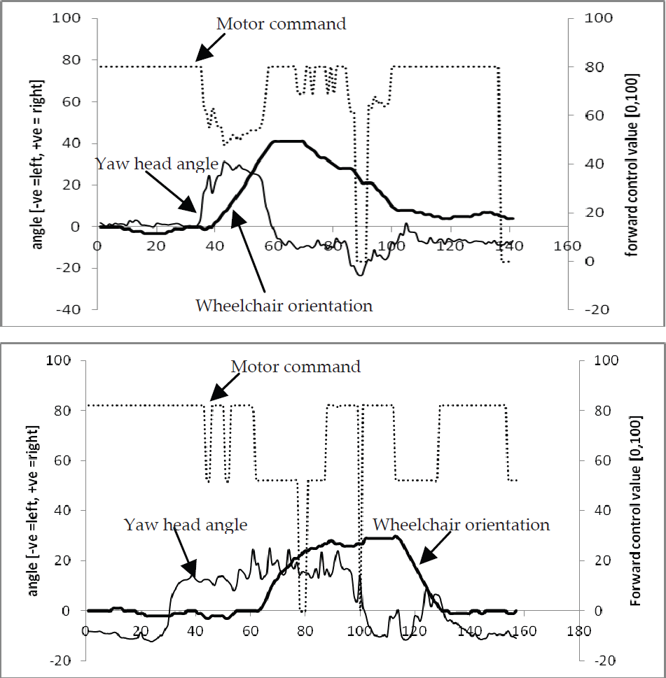
Wheelchair behaviour when the when response to HFI command in manual mode (top) and semi-auto mode (bottom).
The wheelchair response may be different in the semi-auto mode than in the manual mode, since the head direction is effective only when facing an obstacle (i.e., the goal being blocked). As shown in Figure 22 (bottom), in frames #60 to #130 the wheelchair performs an avoiding action. It is clearly seen that the direction to steer away from the obstacle is tailored with the head angle direction, which is to the right. Therefore we conclude that, the planner can properly respond and execute the user preference when navigating under semi-auto mode.
In the second experiment, we investigated the planner response when the user steered the wheelchair in an environment as illustrated in Figure 14 (c) and intentionally issued a command subject for collision. In the manual mode (Figure 23 (top)), as we showed previously, the driving signal should follow the user's gaze direction. However, as seen in frames #40 to #100, the system did not execute the user's command (motor command=0) since it was not safe and the wheelchair remained still. Later on, when the user commanded to the left (frames #100 to #110), since the steering command showed no possibility of collision, the system properly responded to execute it.

Wheelchair behaviour when blending the HFI command with the safety map information when in manual-mode (top) and semi-auto mode (bottom).
On the other hand, in the semi-auto mode, the wheelchair reaction to facing the same situation was different. Again, as shown previously, the direction for avoidance will usually follow the gaze direction closely. However, this was not in this case. As shown in Figure 23 (bottom), when the wheelchair faced the obstacle in frame #40, the user gave a suggestion to the right. However, since it was dangerous, the planner rejected the command and instead steered to the left to maintain safety. Once it reached an appropriate space, in frames #50 to #70, the wheelchair corrected the heading direction to face the goal location. This reactive behaviour is beneficial to the wheelchair by providing help to the user by automatically passing through obstacles, especially when the space is tight, provided that the planner can sense the environment accurately. Besides such cases, the planner can move the wheelchair by following the user's preference while avoiding obstacles.
6. Conclusion and Future Work
In this paper, we have proposed a wheelchair framework to enhance the manoeuvrability for users with severe motor impairment. With the use of hybrid HFI, the user can manually steer the wheelchair in an easy and natural way. We have shown that the proposed interfaces can achieve fair performance in terms of smoothness and distance of travel compared with a standard joystick. To monitor the environments, the developed system can sense almost all possible threats in indoor environments and generate the 2D grid safety map. The map includes positive, negative and overhanging obstacles. From the analysis of each component, the system is proved to reliably detect obstacle locations with a high precision. By incorporating the safety map, the wheelchair can avoid collision in both modes (i.e., manual and semi-auto) and hence, can reduce the user's burden of continuously monitoring the surroundings while manoeuvring.
For real implementation, execution time is crucial since the system needs to respond as soon as any threat is detected. For the developed systems, the vision part requires around 83ms for accomplishing 3D data mapping. When integrating the IMU sensor and the laser range finder, overall processing time slightly increases since the laser sensor requires 25ms to complete a cycle of scanning and the IMU requires 5ms acquisition time. In total, the processing time is 113ms, or 8 frames per second. For our need, such processing time is enough for the wheelchair to receive, evaluate and execute the user's commands appropriately. In future work, we will improve the reliability of each component of the system and evaluate it through operation experiments by actual wheelchair users.
Footnotes
7. Acknowledgments
This work was supported in part by JST PRESTO, A-Step and KAKENHI (22243037, 24700157).