
Abstract
In this article, we present an obstacle avoidance controller implemented in a field programmable gate array for an electric wheelchair. It is based on a traditional approach with ultrasonic sensors and fuzzy logic. Various tests were conducted to characterize the prototype and to evaluate the controller performance. The results showed that the system is able to acquire data from sensors and make decisions 46.16 times per second. The sensors’ coverage extends 3 m to the front, rear, left, and right sides of the wheelchair; moreover, the sensors detect 0.95-cm diameter objects at 40 cm. The power consumption was evaluated, and it was found that the hardware architecture reduces the battery life by only 0.87%. Furthermore, the controller helped to navigate in confined areas, avoiding obstacles with cautious movements and decreasing the likelihood of collision. The proposed methodology uses data from eight sonars distributed around the wheelchair to make navigation decisions, besides the hardware-based architecture guarantees real-time control and on-time response.
Keywords
Introduction
According to the study by Fehr et al., 1 a survey about wheelchair users in the United States reported that up to 40% find difficulties in maneuvering as a consequence of disabilities. Those individuals experiment limited mobility due to visual impairments, spasticity, tremors, or cognitive deficits. Indeed, the development of automated navigation systems would benefit these persons in their daily activities.
“Smart wheelchairs” integrate navigation systems and add-on modules in conventional power wheelchairs, as presented by Simpson. 2 Nowadays, the state of the art and other trends have been presented by Leaman and La 3 and Desai et al. 4 It is recommended the use of a collaborative scheme or semiautonomous control by Nisbet 5 and Hsu et al., 6 and hence, the user is still able to drive the wheelchair by himself and the semiautonomous system complements the driver’s skills.
Within the developed semiautonomous prototypes, a general-purpose task is used to avoid obstacles in unknown and dynamic scenarios. The traditional solution relies on the use of sensory systems for detection and range measurements, such as bumpers, infrared (IR) sensors, and ultrasonic sensors. Particularly, smart wheelchairs that use sonars have been devised by Levine et al., 7 Bourhis et al., 8 Simpson et al., 9 and Tyagi et al. 10 Those sensors are low cost, besides they provide reliable measurements and a quick response. The sonars determine distances to objects by measuring the time-of-flight (TOF) between an emitted ultrasonic burst and its echo. However, sonars commit errors when the incidence angle is bigger than 45° or when the reflecting surface is too small to return enough signal. In order to overcome those problems, a combination of sonic and IR sensors was explored. 11 –14 The IRs emit light pulses, but this could be ineffective on absorbing materials or transparent surfaces. Furthermore, the utilization of laser range finders (LRs) has been widely used in other smart wheelchairs, presented in the literature. 15 –22 The LRs offer the best accuracy for distance measurementsand a two-dimensional scan of the environment. Nonetheless, those sensors are far from being economical, their power consumption is high (a big problem for the wheelchair batteries), and their size limits mounting too many on any wheelchair structure.
Late detection systems integrate a combination of cameras and range sensors for collision avoidance. For instance, machine vision technology with cameras and IR sensors is implemented by Gomi and Griffith 23 ; meanwhile, an anti-collision system based on a stereovision camera is presented by How et al. 24 and stereoscopic cameras are used for three-dimensional (3-D) depth perception in the study by Nguyen et al. 25 The prototypes 26,27 dealt with the problem by combining an LR and a kinect sensor for 3-D mapping and also the kinect was used to detect obstacles 28 Furthermore, a collection of sensors has been implemented in other prototypes 29,30 including the kinect, LRs, IRs, and ultrasonics. Finally, in the study by Zhang et al., 31 there were used LRs, ultrasonics, and two webcams for obstacle localization. Other prototypes have used specialized software for machine vision and robot control; for example, Baya et al. 32 and Cavanini et al. 33 took advantage of the robot operating system (ROS) combined with cameras and different sensory systems.
Furthermore, the use of specialized software for machine vision and robot control is now a trend because of its versatility; for example, Baya et al., 32 Cavanini et al., 33 and TalebiFard et al. 34 used the ROS combined with cameras and different sensory systems. Despite the promising advantages of the vision hardware, its multiple functions are highly attached to the software and the processing core. Cameras share data by serial protocols with a computer running the machine vision software. Under this scheme, the overall system response relies on the computer’s processor resources, which are responsible for handling images, obtaining environmental information, calculating actions, and making the navigation decisions. Finally, the problem is related to the collision-free navigation of intelligent hospital beds. It was developed by Wang et al., 35,36 a methodology for a robotic hospital bed with autonomous navigation.
At this point, all the reviewed systems have demonstrated to be useful, but very few of them preserve secure conditions against software crashes. Those software-based systems are highly vulnerable to crash at multiple levels, for example, the operative system or the application information interfaces. The main weakness in those smart wheelchairs is the processing core: even if it is fast, it does not assure a real-time control or on-time wheelchair response. Consequently, the user’s security is compromised.
A more reliable approach is the use of hardware-based architecture, which involves the application of field programmable gate arrays (FPGAs). These devices are silicon chips with reconfigurable logic gates, and their functionality is defined by the user. FPGAs have proven to be very efficient, as they execute calculations in hardware and do not depend on any operating system. Other processor cores run one instruction at a time, while FPGAs execute parallel instructions within a single clock cycle. There are many advantages about configuring a controller in an FPGA instead of using a computer or a microcontroller, as explained by Bryner and Parnell. 37
Admittedly, FPGA applications for electric wheelchairs have been presented in the literature 38,39 ; however, they are not related to the navigation control. The former is related to the energy driving of the direct current rim motors using a fuzzy controller, and the second is related to a digital parallel fuzzy controller for steering an electric wheelchair. Moreover, the system presented by How et al. 24 involves an FPGA for image processing, but the data are finally analyzed by a single-board computer to make the navigation decisions.
For deploying an automatic navigation control for a smart wheelchair, with real-time response and high-speed processing, this article proposes a fuzzy logic controller (FLC) implemented in an FPGA. As mentioned by Hong et al., 40 fuzzy logic is a robust and reliable methodology that tackles environment and sensor uncertainties. A navigation control system for a mobile robot is described by Melendez et al. 41 Besides, fuzzy logic requires a low computational complexity compared with other navigation schemes used for avoiding obstacles, such as vector field histogram (VHF). 42 As presented by Baklouti et al., 28 VHF is computationally expensive and its convergence is not always ensured such as in U-shaped corridors. Furthermore, fuzzy logic does not need local or global maps, besides it can be used to prevent collisions in unknown and dynamic environments in a real-world application. The FLC methodology for mobile robots is described by Omrane et al., 43 and there are several smart wheelchair prototypes that use an FLC as the main control technique and range sensors as inputs. 10,11,28,44 –46 The proposed FLC runs in the FPGA at a high-speed rate and guarantees the wheelchairs reactions on-time, as this system acquires data from sensors and makes decisions within 46.16 times per second.
Methods
The electric wheelchair architecture
The overall architecture is presented in Figure 1. The hardware was incorporated into a commercial wheelchair Quickie P-222 SE (Sunrise Medical (US) LLC, Fresno, CA). The main core is the FPGA, included in the National Instruments CompactRIO (cRIO-9103). The FGPA is a Virtex-II (Xilinx) chip with 3 M system gates, 14,336 slices, 448 Kbits RAM, 96 multiplier blocks, and a maximum of 720 available I/O pads. The code, programmed with the LabVIEW FPGA [version 2015] toolkit, is divided into two blocks: the TOF for driving the sensors and the fuzzy controller for avoiding collisions.

The components of the wheelchair.
For acquiring the distance data, two high-speed digital modules NI 9401 were interfaced with eight Parallax PING))) sensors. The FPGA has a 40-MHz default clock, which means that the processor is able to respond within 25 ns cycles; however, the distance scanning process is limited by the sensor’s operation to 20 ms. Because of the FPGA parallel architecture and the high-speed response from the digital modules, that sampling rate is guaranteed for each sensor simultaneously.
The wheelchair movement is controlled by two analog voltage channels, provided by the NI 9263 module. There are used two analog channels, with a sampling rate of 100 kS/s and 16-bit resolution for each output. Therefore, this module provides accurate signal generation for controlling the wheelchair. Finally, the cRIO-9013 communicates, by a standard Ethernet connection, with a host laptop running the human–machine interface (HMI).
The FLC strategy
The FLC changes the wheelchair speed and orientation according to the distance measurements and the “change rate” inputs, which detect abrupt changes in distance measurements. The change rate inputs are calculated from the current and past distance samples, as presented by

where Sn(k) is the current distance measured by the sensor n and Sn(k − 1) corresponds to the past sample.
According to the proposed architecture, data from eight sensors are used as inputs for the FLC; however, including many inputs outcomes in a complex and nonpractical combination of rules. To make possible the implementation, four individual cases with few inputs were considered: forward obstacle avoidance (FOA), left collision detector (LCD), right collision detector (RCD), and backward collision detector (BCD). Those cases are activated one at a time according to the virtual joystick position. Moreover, it is proposed the combination of two inputs using the fuzzy conjunction AND/MIN. This simplification helps to widespread the coverage range without adding more sensors or rules. The FLC structure is shown in Figure 2.

The sensors distribution and the fuzzy logic controller structure. The distance inputs are labeled from S1 to S8.
Fuzzification of the variables
The input variables Sn (distance) are defined by the trapezoidal fuzzy sets C and F (“close” and “far”). Those membership functions are shown in Figure 3(a). The dSn (“change rate”) inputs are defined by a trapezoidal set named GF (“getting fast”), presented in Figure 3(b). Further, the output variables M and D (“movement” and “direction”) are presented in Figure 3(c) and (d). The M output is defined by the four linguistic variables: B, N, SF, and F (“back,” “null,” “small forward,” and “forward”). The D output is defined by the five linguistic variables: L, SL, N, SR, and R (“left,” “small left,” “null,” “small right,” and “right”).
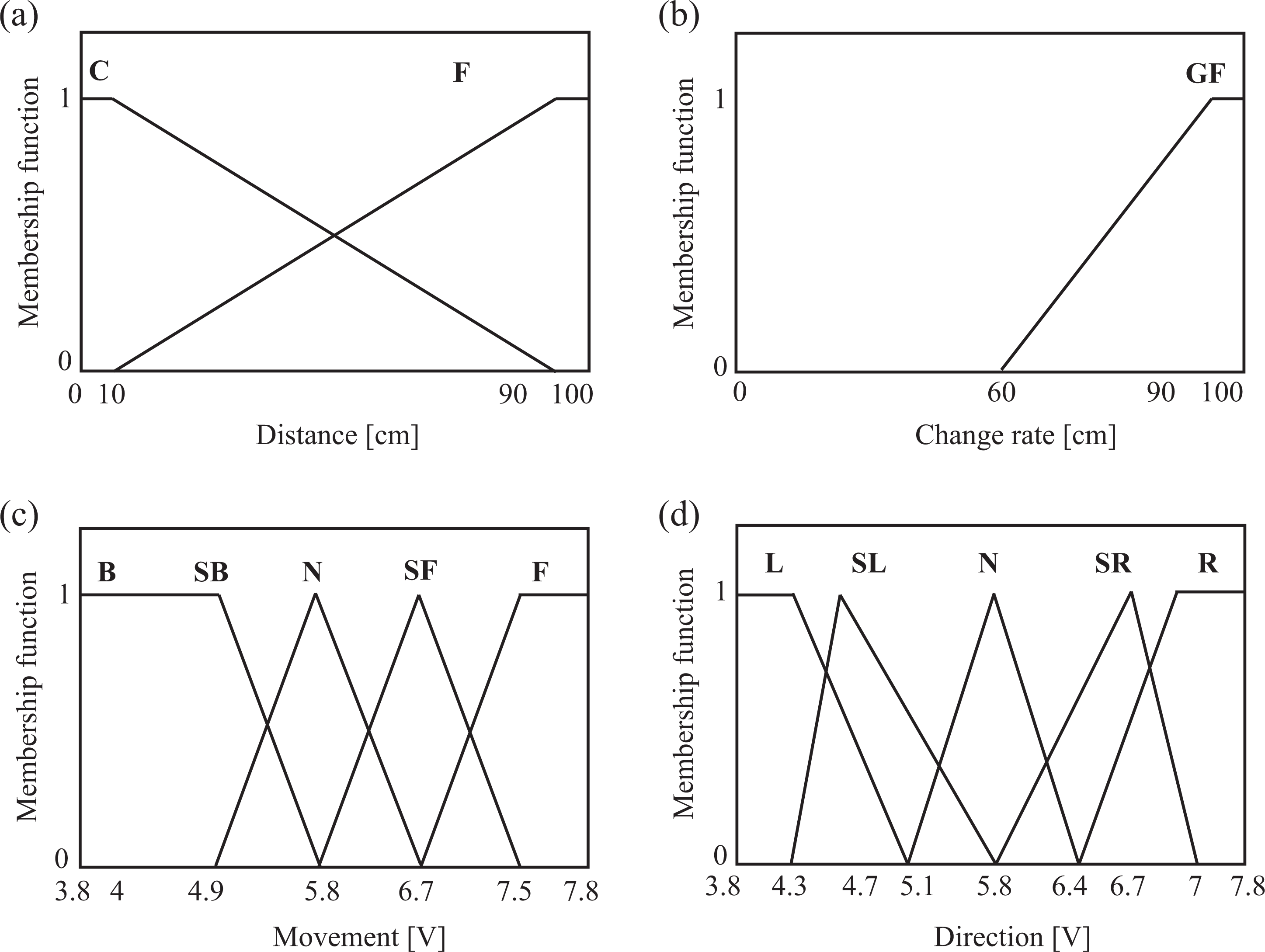
Membership functions for the obstacle avoidance controller: (a) input sensors S1, S3, S6, and S7; (b) input sensors S2, S4, S5, and S8; (c) output movement; and (d) output direction.
The rules base and the inference engine
The wheelchair must prevent collisions with static and dynamic objects (like a person walking) in any environment. The main idea is simple; when a sensor detects an object, the wheelchair must turn, change its speed, or stop if it is necessary. In Figure 4, there are four configurations to analyze how the system behaves under different conditions.

Navigation scenarios: (a) static obstacles, (b) dynamic obstacles, (c) lateral obstacles, and (d) rear obstacles.
The next step is considering the possible navigation cases with different input conditions and what actions are needed to do. Those situations are enlisted in Table 1. Finally, the rules are defined formally with the input and the output variables.
Navigation cases for the fuzzy rules.

The complete rule set for the FOA, LCD, RCD, and BCD cases is shown in Table 2. Each case possess its own rules: FOA is an obstacle avoidance controller with nine rules, which uses sensors from S1 to S5; the LCD and RCD are used to detect obstacles on both sides of the wheelchair, using as inputs S4 and S5; and finally, the BCD is used to stop the backward movement if any of the rear sensors S6, S7, or S8 is blocked.
Rule set for the fuzzy navigation assistant.

FOA: forward obstacle avoidance; LCD: left collision detector; RCD: right collision detector; BCD: backward collision detector.
Defuzzification of the outputs
The Mamdani model uses the inferred set shape for calculating the crisp outputs of the system. The defuzzification block uses the center of gravity to evaluate the area under the scaled membership functions.
The semiautonomous smart wheelchair operation
The smart wheelchair can be maneuvered with a virtual joystick, implemented in the HMI. The virtual joystick functions similarly to a physical one: if the individual drags the cursor from its home position, the wheelchair starts moving with that speed and orientation. When the user releases the cursor, it returns to the home position and the wheelchair stops.
The user is able to maneuver in normal or assisted mode. In normal mode, the wheelchair steers according to the user; however, in the assisted mode, the control is shared with the FLC. The four controller modes are selected according to the virtual joystick position. In particular, the FOA is activated by dragging the cursor along the positive y-axis and the BCD is activated by dragging the cursor along the negative y-axis. Similarly, the LCD is activated when the cursor is dragged to the negative side of the x-axis and the RCD controller is activated when the user drags the cursor to the positive side of the x-axis. Moreover, when the cursor is dragged diagonally to any axis, the wheelchair returns to normal mode. Under this scheme, the user is able to switch between collision assistants and maneuver manually when it is necessary.
Tests and results
Several tests were done in order to characterize the sensory system and the hardware implemented in the wheelchair. In addition, the smart wheelchair was steered by one of the authors to observe the FLC utility in different scenarios. Both evaluation sections are described next.
Prototype characterization
Sensor’s sampling rate
A sample rate of 50 Hz was configured for data acquisition; however, this value changes when the FLC is running. The evaluation of this parameter was done using the LabVIEW tick count function, which measures the cycle length. When the FLC was active, the measured cycle length was 21.66 ms, which represents a real execution rate of 46.16 Hz. Within this cycle time, data acquisition and processing are executed.
Sensor’s coverage
This test was done to determine the sonar’s coverage and the wheelchair’s blind spots. A mapping of positions was drawn, using a 1.8 × 2.4 m (5.9 × 7.87 ft) grid, with a resolution square of 5 × 5 cm (0.16 × 0.16 ft). The wheelchair was placed in the middle of the grid, filling 288 of the 1728 squares. A square wood dowel, whose dimensions were 40 × 40 × 62 cm (1.31 × 1.31 × 2.03 ft), was placed in all the grid positions to verify detection. The measured distance was considered valid or invalid by comparing it with the grid dimensions. The process was repeated for the 1440 positions and the results are presented in Figure 5, where the sensory system’s coverage is indicated by the dark areas. The coverage mapping was extended to 60 cm from the stationary wheelchair to the left, right, front, and rear sides.

The sensor’s coverage map. The dark areas indicate the detection positions in a grid resolution of 5 × 5 cm.
Detection of small objects
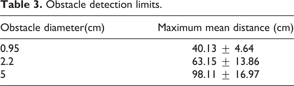
The evaluation was done using three tubes with different diameters. Those objects were placed in front of every sensor at different distances. The maximum distance for detection was considered the limit where the sensor loses the object. The collected data from the eight sensors were averaged, thus the values of maximum mean distance and standard deviation (SD) are presented in Table 3.
Obstacle detection limits.
Wheelchair’s safe power level
As indicated on the Quickie P-222 SE datasheet, the wheelchair’s speed at full power is 3.79 m/s (8.5 mph). This power can be adjusted manually with a knob control. The FLC adjusts speed according to the space conditions; however, it is important to estimate a safe power level for avoiding dangerous collisions.
For this test, the wheelchair was placed 3 m away from a foam wall, as shown in Figure 6, then it was steered forward with different speeds. Because of the controller’s action, the wheelchair must slow down and stop before colliding. This process was repeated 10 times for each power level. In order to register the moment when the wheelchair was stopped, it was used a software chronometer activated automatically by the controller outputs. When the front sensor detects a close distance, the wheelchair must be stopped.

Experimental scenario for determining the wheelchair’s safe speed for navigation.
The results obtained are presented in Table 4. There are shown different speeds versus the distance at which the wheelchair was commanded to stop, the final distance when the wheelchair really stopped and the speed versus the trial time and the number of collisions. The mean and the SD of the repetition values were calculated and presented in Table 4.
Collision test results.

For the speeds 0.65, 0.86, and 1.06 m/s (1.45, 1.92, and 2.37 mph), no collisions occurred as the wheelchair was able to slow down when the wall was nearby, thus those power levels are considered safe. However, for 1.25 and 1.47 m/s (2.79 and 3.28 mph), there were collisions during all the attempts. As a consequence, those power levels are considered unsafe. To prevent accidents in other trials, it was important to use the minimum power level and the safe speed of 0.65 m/s (1.45 mph). In addition, the navigation scenarios were built with foam blocks to prevent damages.
Hardware power consumption
The power consumption of the hardware presented in Figure 1 was measured. There are two parts, which operate at different voltages: the first part uses a 12 V and it is integrated by the power supply circuit for the sensors and the bidirectional interface; and the second part is the cRIO-9103, which uses a 24 V supply. The power consumption was calculated by measuring the currents and voltages when the FLC was active and inactive.
The power consumption results are summarized in Table 5. It is clear that the maximum power consumption occurs when the controller is active.
Power consumption of the assistance system.

FLC: fuzzy logic controller.
FPGA device utilization
After the compilation, the device utilization report for the implemented system was obtained. The report is presented in Table 6.
Device utilization report.

LUTs: Look Up Table; RAM: Random access memory.
FLC navigation evaluation
FOA considers many rules for avoiding obstacles, as presented in Table 2. In comparison, LCD, RCD, and BCD only stop the movement if obstacles are detected as the user turns the wheelchair or moves backward. According to the sensory system characterization, the limitations for those tasks are the coverage area shown in Figure 5, the size of the objects, and the wheelchair speed. For that reason, navigation tests were done only to evaluate the FOA performance. The test was developed in different scenarios, described as follows.
Corridor navigation
It is expected that the FOA assistant will help the users to navigate through long and narrow corridors. For this case, a 6-m long corridor (19.68 ft) was built. Five navigation repetitions were done; however, different widths were used: 2.5, 2, 1.5, 1, 0.8, and 0.7 m (8.2, 6.56, 4.92, 3.28, and 2.62 ft). The widest and the narrowest corridors are shown in Figure 7.

Experimental scenarios: (a) 2.5-m corridor and (b) 0.7-m corridor.
During the five iterations, the wheelchair was able to complete the trial without colliding, even in the narrowest corridor. The relation between the base speed (0.65 m/s) and the speed observed at the different corridors is presented in Table 7. It was observed that the speed changed according to the corridor space. For the 2.5 and 2 m corridors, the speed was unaffected; however, the speed decreased to almost the half in the narrowest corridor. No collisions were observed during this test.
Speed reduction in different corridor widths.

Corridor with obstacles
There were done five navigation attempts assisted automatically by the FOA. For comparison, other five trials were done by steering manually with the virtual joystick. The trajectories were recorded on video and marked using the VideoPoint Physics Fundamentals software [version 1.0]. In the first case, it was expected that the wheelchair could steer inside a corridor to avoid collisions automatically. The corridor, whose dimensions are 4.8 m length and 2 m width (15.74 × 6.56 ft), contains square obstacles of 0.6 × 0.6 m (1.96 × 1.96 ft).
Figure 8(a) shows the obtained trajectory during one attempt. Moreover, in Figure 8(b), it is shown the trajectory obtained by manual control. The average time for both cases and the total number of collisions registered are presented in Table 8. The time corresponding to each trial was measured, besides the mean and the SD were calculated. The SD for the automated navigation was small, which indicates that the trajectories were similar during all repetitions. However, the SD for the manual control indicates more variations in the time registered between each test.

The obstacle avoidance action in a corridor: (a) assisted automatically by the fuzzy controller and (b) controlled manually by the user.
Test time and number of collisions for the navigation experiments.
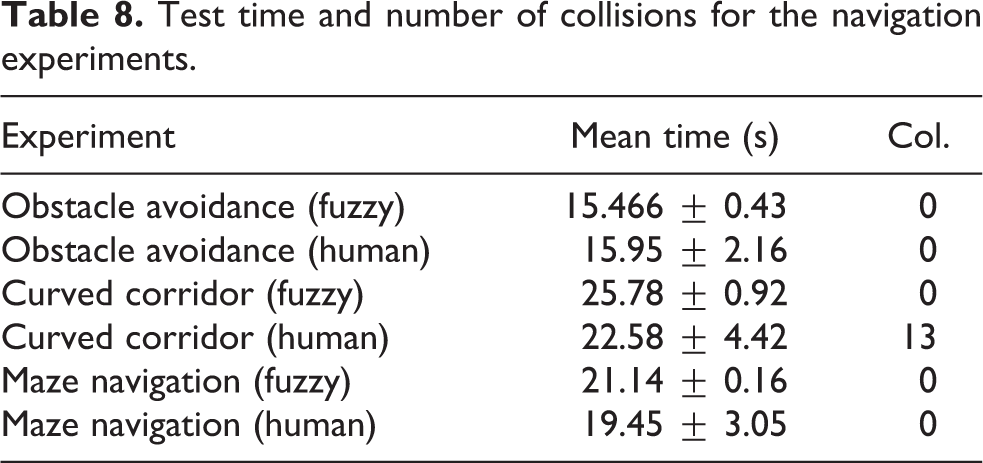
No collisions were registered during the trials; however, using the manual control, some movements were abrupt and hesitant.
Curved corridor
The FOA allows the wheelchair to navigate inside an irregular shape corridor, like the case presented in Figure 9. The space is narrow; thus, it is difficult to take the curve.

Navigation through differently shaped corridors: (a) assisted automatically by the fuzzy controller and (b) controlled manually by the user.
The fuzzy assistant helped to complete the navigation without difficulties, as shown in Figure 9(a). However, in the manual case presented in Figure 9(b), it was hard for the user to avoid abrupt movements. Moreover, it was easy to lose control and several collisions were registered.
Navigation in a small maze
For this test, a small maze was built inside a square room of 3.6 × 3.6 m (11.81 × 11.81 ft). The wheelchair, starting from one corner, had the objective to leave the maze. The obtained trajectory for the case assisted by the FLC is presented in Figure 10(a). No collisions were registered within this mode and the user was able to leave the room in every attempt. However, in the trajectory obtained during the manual control, shown in Figure 10(b), there were collisions with the walls. This trajectory shows that the user had difficulties in controlling the wheelchair because of the maze shape and the narrow space. The consumed time, the mean, and the SD were obtained for each scenario, as shown in Table 8. The SD for the automated attempt is small, thus the trajectories were similar during all the iterations. However, the SD for the manual tests indicates variations in the time registered between each test, which indicates that the attempts were irregular.

Navigation through the maze: (a) assisted automatically by the fuzzy controller and (b) controlled manually by the user.
Discussion
Prototype characterization
As mentioned in the study by Lopresti et al., 13 the sensor’s sampling rate is a major aspect for robotic wheelchairs. Microcontrollers and computers use sequential processing architectures, thus the consumed time is accumulated from each line of the code. On the other hand, the parallel architecture implemented in this prototype allows to get data from the eight sensors, simultaneously, to process the information, and to make navigation decisions every 21.66 ms. According to the sonar datasheet, the fastest time for taking measurements is 19.255 ms, however, to drive eight sensors in any software architecture (even a real-time software) that value is accumulated by each sensor, besides the time for passing data to the computer and the processing time. As a consequence, it is very difficult to consider sampling eight sensors with any software-based system at a high-speed rate.
The sensor coverage map presented in Figure 5 shows representative data about the sensor’s coverage at short distance. It shows a cone shape extending from the emitter to 3 m, according to the sensor’s range. Besides, the mapping shows clear areas at short distances and the coverage overlap in some areas. To augment the chances of detection, some fuzzy rules from Table 2 were designed to join the coverage cones together. As an example, the FOA controller is able to detect objects in the dark areas covered by sensors S1–S5, thus the object is likely to be detected before reaching the clear positions. In addition, the high sample rate reduces the probability of missing an object during the navigation.
The results presented in Table 3 show that the sensors are able to detect small objects at close distances. The smallest object was detected at approximately 40 cm (1.31 ft), and the SD confirms that this is a regular value for the eight sensors. Furthermore, the object size is not a problem, but its shape affects the signal reflection. Some objects are invisible to the sensors because of their orientation not because of their dimensions. Finally, another limitation observed is that the PING))) sensors cannot measure accurate distances to objects behind 3 m (9.84 ft). Thus, detection for this prototype is limited to 3 m.
According to the data presented in Table 4, the speeds at 0.65, 0.86, and 1.06 m/s are safe as no collisions occurred. However, the speeds at 1.25 and 1.47 m/s are unsafe, because all the trials ended with collisions. The registered stop value is similar for all the power levels, which implies that the controller reacted at the same moment during all the tests. Likewise, after comparing the stop and the final values, it is clear that the wheelchair kept moving after the controller stopped the motors but slight variations occurred because of the acceleration. This difference is more prominent in the upper power levels. Despite the controller’s capacity to react when an object is detected, the wheelchair’s mechanical system is not fast enough to stop the movement. At the unsafe speed levels, the difference between the stop distance and the final distance is more than 40 cm (1.31 ft), which means the wheelchair kept running after the controller slowed the motors. On the contrary, for the safe speed levels, the stop distance and the final distance present similar values as the wheelchair was able to stop before colliding. The Semi-autonomous Smart Wheelchair immediate reaction is not related to the sensor rate, but it depends on the wheelchair’s physical and mechanical characteristics.
In relation to the power consumption, the wheelchair uses rechargeable sealed lead-acid batteries, whose nominal voltage is 12 V and 35AH. The maximum consumption of the additional hardware in our prototype is 7.76 W, which compared to the 26.6 W calculated in the study by Lopresti et al., 13 do not represent a significant consumption for the batteries. The energy consumption of the installed hardware in our prototype is 7.76W. As indicated in that article, 26.6 W reduces battery life by 3%; meanwhile, our power consumption reduces battery life only by 0.87%. Consequently, the use of the FLC will not affect the battery life or the daily charges. Power consumption is an important factor to be considered when adapting commercial wheelchairs as indicated by Mazo et al. 12
Finally, for the device utilization, the implemented code uses a lot of the FPGA resources as seen in Table 6. A code optimization will be necessary for a future version.
FLC navigation evaluation
According to the corridor navigation with FOA, the fuzzy controller fits the wheelchair speed according to the space in corridors. Despite the speed reduction of 50% for the narrowest corridor, the wheelchair was able to complete the task without colliding. In that corridor, the space between the wheelchair and the walls was minimal.
For the navigation comparison between the manual and the automatic assistance, the tests showed that it is unsafe to complete the tasks solely by human skills. After several repetitions using the manual control, the task is likely to be completed with less problems. However, the user tends to make abrupt movements when he tries to correct his orientation. In confined areas, the user has to be very accurate with the joystick operation. However, for users with disabilities, this is complicated. The comparison between the trajectories presented in Figures 8 to 10 showed that the FLC helped to complete the task without collisions during the attempts.
Limitations
The sensor coverage was studied in two dimensions, but the signal is actually omnidirectional. As a consequence, the sensors could have different behaviors depending on its height position. This effect was not considered in the research.
The other prototypes presented in the literature 7,44,47,48 included additional behaviors such as door passing or follow walls. For this controller, it will be important to optimize the FPGA code to include more behaviors.
It was observed that the fast data acquisition and processing do not impede collisions because the mechanical system is not able to react immediately. Moreover, the wheelchair does not possess a braking engine to stop instantaneously.
The LCD, RCD, and BCD were not evaluated with the similar tests presented for the FOA. However, their operation is related to the sensor’s coverage and response.
Finally, the tests were done inside the laboratory under specific temperature and lighting conditions. No navigation tests were done with rehabilitation patients or user with disabilities.
Future work
In order to implement more functions for the navigation assistant, it will be important to optimize the FPGA code. It is necessary to develop a test protocol for the different navigation modes and with other users. Finally, it is very important to test the prototype with end users and specialized rehabilitation personal counselors to show the system usability and improve its functionality.
Conclusion
A navigation assistant was implemented in a commercial wheelchair. The tests indicated that the system’s architecture based on the FPGA, a fuzzy logic methodology, and ultrasonic sensors provide secure navigation. Furthermore, the controller is independent from software execution, which assures data acquisition from eight channels and data calculations within 21.66 ms. The sonars are able to detect different objects around the wheelchair, besides the fuzzy rules merge the sensor’s coverage to detect objects in critical points. Despite the immediate reaction of the controller, the wheelchair mechanical response is not immediate. Consequently, a safe speed of 0.65 m/s was determined. There were done tests within confined areas, which showed that the FLC modifies this speed in order to make cautious movements. Furthermore, the use of the FLC to maneuver in three different unstructured scenarios was validated. It was shown that the implemented system can help users who find it difficult to operate a wheelchair, as the assistant prevents collisions with objects when the user navigates in all directions.
Footnotes
Declaration of conflicting interests
The author(s) declared no potential conflicts of interest with respect to the research, authorship, and/or publication of this article.
Funding
The author(s) received no financial support for the research, authorship, and/or publication of this article.