
Abstract
Providing an assistive navigation system that augments rather than usurps user control of a powered wheelchair represents a significant technical challenge. This paper evaluates an assistive collision avoidance method for a powered wheelchair that allows the user to navigate safely whilst maintaining their overall governance of the platform motion. The paper shows that by shaping, switching and adjusting localized potential fields we are able to negotiate different obstacles by generating a more intuitively natural trajectory, one that does not deviate significantly from the operator in the loop desired-trajectory. It can also be seen that this method does not suffer from the local minima problem, or narrow corridor and proximity oscillation, which are common problems that occur when using potential fields. Furthermore this localized method enables the robotic platform to pass very close to obstacles, such as when negotiating a narrow passage or doorway.
Keywords
Introduction
Navigation in the robotic arena can be described as the guidance of a robot towards a goal whilst avoiding obstacles; however, those tasks must be undertaken with consideration to the platform kinematic constraints and dynamic behaviours. When we consider assistive, or semi-autonomous, robotics with the human in the loop – such as robotic wheelchairs and remote tele-operated platforms – we need to remove the autonomous high-level functions that perform tasks such as high-level path planning and targeting, or goal seeking [1]. The reason is that in reality, a conflict of interests may well occur; for example, the platform system takes its trajectory from the user's desire for something, possibly, as a result, causing some injury or damage (or at best apprehension) when using the system [2].
For many users, the operation of powered wheelchairs in enclosed environments, such as buildings, proves problematic. An important need is to be able to drive in such environments with minimal collisions. For those users with significant physical disabilities, accurate control of the chair is a major challenge. The inability to avoid colliding with objects or other persons can deter the user from driving or may even cause the removal of the option of independent powered control because it presents an unacceptable risk to the user, to others and to the environment.
Developing intelligent assistive systems is, therefore, a significant challenge for the research community. Finding solutions that assist the user with collision avoidance and assisted navigation are two requirements that would help to maintain the independent mobility of the PWC user.
Assistive systems need to operate safely in the dynamic human environment. For example, the system must only operate positive action when the operator is in the feedback and feed-forward control loop. Furthermore, any assistive trajectory must be smooth and locally acting to damp over-action whilst remaining adjustable. For example, the user may wish to manoeuvre close to a bed or desk, making deliberate and gentle contact with those obstacles not affected by the assistive robotic system.
A review of robotic control architectures and their effectiveness in 2011 [3] identified that reactive architectures performed significantly better than deliberate ones in an uncertain and dynamic environment; however, in order to achieve comprehensive navigation, a reactive robot would require real-world representation, perception and decision-making. By combining the Deliberative Control Architecture and the Subsumption Architecture, Arkin formed the Hybrid Control Architecture in 1989 [4]. This allows the top-down directives to provide the higher level dictates, such as real-world navigation and decision-making, and the lower level reactive architecture to deal with real-time collision avoidance, passing control back to the upper layers when it is unable to resolve the situation locally. Nakhaeinia [3] reports that this combined hybrid architecture provides a much better solution to autonomous robotic navigation than either method individually.
By taking the network concept for providing a better interconnected Subsumption Architecture [5], combining this with the Hybrid Control Architecture [4] and then introducing a human into the network, it is proposed that a more robust architecture for assistive mobile robotic control can be described than the one represented in Fig 1. This new human-in-the-loop Assistive Control Architecture (ACA) for assistive mobility devices provides a full interconnection between the higher layers and lower layers, in a top-down and bottom-up directive, unlike the previous architectures.
The ACA prevents the higher levels from subsuming the lower layers if the lower levels are still active. For example, the collision avoidance layer will not be overridden by the assistive trajectory level if there is an unpredicted interruption or undetected obstacle. Instead, the collision avoidance layer overrides the assistive trajectory layer, or alters the trajectory in a complementary fashion, whilst informing the user and higher levels. This new method allows the human to be the decision-maker whilst the ACA provides assistance.
Following on from this proposal, we have developed a new collision avoidance method based on using a potential force field as a moderating input on the desired trajectory. The repulsion generated by the nearest obstacle in each region of interest or zone is used to dampen the input to the drive motors. Therefore, the user has to deliberately drive the platform towards obstacles, for example, if should they wish to make contact with that obstacle. When the platform velocity input is used to adjust the damping co-efficient, the platform motion can be made to match the natural human trajectory, and a sudden jerk of the joystick or excessive joystick motion has no effect on the platform motion.
Our localized potential force field is then used as a dynamic workspace, travelling with the platform and acting upon the nearest obstacle rather than on all obstacles, as is conventional. We treat the platform not as a point mass but as a novel, geometrically shaped workspace that better represents the kinematic constraints and dimensions of the platform.

Human-in-the-loop Assistive Control Architecture for assistive mobility devices
In the next section, we define the problems we faced when developing human-assistive mobile robotics. The research background and state-of-the-art of the smart powered wheelchair follows. Next, we present our collision avoidance method that improves upon existing technology. We confirm this through experimentation using a test platform and finally conclude that the dynamic localized adjustable force field method (DLAFF) is compatible with the requirements for human-assistive wheelchair navigation.
Assistive technology developments, such as smart electric wheelchairs, are mobile robotic interactions that are traditionally bound to carefully controlled workspaces, increasingly towards uncertain and complex human environments. Seamless crossovers between human-defined desired trajectories and traditional, autonomous system-aided trajectories are required. Human-assistive systems place the intelligent user in the loop [1, 6] and, according to Matuszek et al. [7], this requires a stochastic and semantics-based workspace. Methods commonly employed in the Euclidean geometric domain, such as covariance ellipses indicating location and object uncertainty, now for assistive technologies may require weighted nuances, with obstacles and targets having a spectrum of importance.
Some of the main considerations for human-in-the-loop assistive mobile robotic platform development, according to the literature [1, 8–10], can be listed as follows:
possible injury to pedestrians,
possible damage to infrastructure,
learning to drive the PWC safely,
manoeuvring in tight spaces,
inability of users to see behind or to the side,
potential of tipping over,
reliability of equipment and
adjustability and adaptability of system/equipment to changing needs.
We considered solving problems 1–4 in this paper by developing a method to:
help correct the user trajectory, even with a small clearance gap between the doorway and the platform,
provide lane following or keeping to one side of the corridor so that people and other platforms have the room to pass without collision,
allow docking or close proximity with an object without a harsh collision,
vary the collision avoidance assistance according to the user's needs,
allow movement in confined spaces while providing collision avoidance and
make the system easily adjustable and configurable.
State-of-the-art for Smart Powered Wheelchairs
An extensive review of intelligent and assistive wheelchair literature was undertaken by Simpson in 2005 [11]; another independent review of the literature was undertaken by Faria in 2014 [12]. Some of the research projects mentioned in 2005 have continued to influence research [13–16], while other new platforms have emerged [17–19] and some 4,018 papers have been published between 2005 and 2013. Despite this significant research, little has been done to bring smart PWCs to the end-users, according to Garcia et al. [14]. They argue that most research is carried out in the lab without recourse to the stakeholders, in particular, to the users.
A collaborative control method (2010) [20, 21] was developed over a number of years at Imperial College London by Tom Carlson; their model, called DLOA, uses local obstacles detected in the vicinity of the user's intended direction (obtained from the joystick) and the system-shaped trajectory in order to avoid the obstacle or to pass through a doorway. If the collaborative controller determines a mismatch between the approach path and a system-generated path, then the system takes control. Their system uses a layered approach: beneath this trajectory assistance, they employ a virtual bumper using sonar-ranging sensors to avoid localized collisions. This layered structure is a common theme, also having been employed in the VAHM [22] and Wheelsley [23] projects, for example.
The ARTY researchers in 2012 [24], following on from Carlson, attempted to use two methods of navigational assistance for their smart PWC. The first method used the Vector Field Histogram (VFH) [25], which proved difficult to tune and adjust, is non-intuitive and relies on the model of the platform being expressed as a point object. The second method used the Dynamic Window Approach (DWA) [26], which is a better representation for taking into account platform dynamics and modelling and was easier to tune and adjust. However, this method was computationally expensive, taking too long to compute solutions. The researchers adopted a novel hybrid approach that provided an approximate solution to the DWA. Another separate development by researchers at the University of Seville has been to modify the DWA method into a shared dynamic control [27].
Methodology For The Dynamic Localized Adjustable Force Field Method (DLAFF)
Potential fields were first suggested by Andrews and Hogan [28] for use with manipulators and later by Katib [29], who included mobile robotics. The concept combines the principle of positive attractive forces acting at the goal, or target, and negative repulsive forces emanating from obstacles. A gradient then forms between the target and the current position of the robot; this forms a gradient descent trajectory from the current position to the target, making potential field methods highly suited to real-time mobile robotics applications [30]. This method has been adopted for collision avoidance with smart powered wheelchairs [31, 32]; road vehicle driving assistance based upon using potential fields to keep vehicles following lanes and utilizing a steering damping method has also been suggested [33].
Urdiales et al. [34] state that many assistive wheelchair collision avoidance systems rely upon the potential field concept or are derived from the method, such as the VFH.
The Virtual Force Field (VFF) [25], which led to the VFH method, was introduced in 1989 as real-time obstacle avoidance for fast robots. VFH utilizes a two-dimensional Cartesian grid, or active window, centred on the vehicle centre point that moves with the platform in the real-world reference frame, thus effectively reducing the world frame area in size to the immediate vicinity of the platform. Ultrasound ranging measurements can then be used to determine the existence of obstacles by using certainty values for each of those measurements in a histogram grid [35], from which a repulsive force vector can be determined. The resultant force vector driving the robot is then the summation of the repulsive vector and the target attractive vector.
We have used the concept of an active window or moving frame and force field to develop our method; however, we propose that the frame should be elliptically shaped, and adjustable in size according to the platform's dimensions and dynamics.
One common problem occurring with the application of potential fields has been the passage of the platform between two close obstacles, such as a doorway [36]. The force field either causes the platform to veer away, if the net magnitude of the driving force is less than the sum of the repulsive forces, or pass through it, if the repulsive force is less than the driving force's magnitude — a problem Soh and Demiris reported when using VFH [24]. We use a nonlinear localized potential field which acts between an inner and outer boundary (surrounding the platform) upon the nearest obstacle, Guldner et al. [36] introduced the concept of representing obstacles as point charges within circular security zones that are inside ellipsoidal gradients, which considered the nearest obstacle and used weighting to avoid discontinuities when switching between zones.
A solution to the local minima problem [37] used a human-robot interaction for the manipulation of potential fields [38] in order to navigate around obstacles. They used the human interaction to shape the potential field such that the two sides of the trap were modified by the human operator and they were ‘pulled’ into a convex boat-like shape, thus driving the robot out of the trapped situation. The development of our ellipse method allows adjustment of the repulsive zones according to the waypoint being negotiated, either by system recognition of the waypoint [39, 40] or by human override.
Platform Kinematic Model
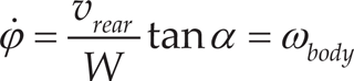
Human transport is largely based upon car-like vehicles, which can all be thought of as acting in a manner whose kinematic modelling can be described as a bicycle model [41]. Another alternative form of transport commonly used is the tank style, or differential drive wheels on the same axle, such as is used on electric wheelchairs; this kinematic model can be thought of as a unicycle [42]. Both the unicycle and bicycle models can be expressed as follows [43]:


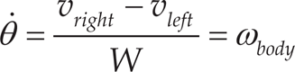
Where:
W = The distance between the two rear drive wheels,
Conventional use of the kinematic models [44] usually divides them such that unicycle-type robots obey Eq. (1) and Eq. (3), whilst bicycle-type robots obey Eq. (2) and Eq. (4). However, it can be clearly seen that the form of both equations are very similar; for example, unicycle robots could be represented as front-wheel driven tricycles, and six common wheel configurations (with 2-degrees-of-freedom or 3-degrees-of-freedom) have been given consideration [45]. However, in all cases, the effective real-world platform trajectory could be said to generally follow the mid-point between the two rear wheels, marked as ‘o’ (z body axis) in Fig. 2, where Eqns. (1) and (2) are effectively the same and describe the rate of translation of the platform at ‘o’ as forward platform velocity (vbody). Eqns. (3) and (4) describe the rate of body rotation (ωbody) about the z body axis on the x, y plane, where θ and φ are the instantaneous tangential heading angle for some time. It can be seen that the steering angle α can be effectively described as a bounded case of θ.
Whilst these simple models describe the kinematic behaviour of these non-holonomic vehicles that they represent, they do not offer any physical Euclidean geometric dimension of the robotic platform, and therefore techniques need to be employed for collision avoidance, such as increasing the protective zone around the robot or the repulsive zone around the obstacles. Furthermore, these simple kinematic models do not take into account dynamic changes such as mass and inertia, velocity and acceleration or gravity and incline: all of which become increasingly important in the dynamic workspace as the kinetic energies of the platform and other dynamic obstacles change.

Platform and ground frame of reference
To address these issues and to develop a better obstacle avoidance model, which can be applied to all platform kinematic models, we have chosen to represent the mobile robotic platform as a differential drive platform with a frame of reference as given in Fig. 2. The rear axle, which we set as the y body axis, has a mid-point marked o, which is set as the z body axis. The x body axis lies orthogonal to the rear axle at that mid-point. The steering angle, or maximum turn angle at which forward motion in the x body axis is still greater than zero, is represented by α, which in our model will be moved to the rear axle mid-point and treated as if it were θ.
If we take our user input desire as a force vector — rather than a velocity vector taken either from a joystick or some other human analogue interface device, or even from some digital threshold value from another human interface that is opposed by an obstacle force vector — then we need to develop the geometric kinematics function into one that better represents a truer model, allowing dynamic adjustments to be made from feedback sensors. For example, inertia and mass need to be considered adjustable due to loading and the gravity vector in order to maintain a constant velocity while driving up an incline, or, conversely, damping to prevent tipping over when turning on a slope.
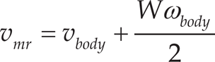
Referring to our method and previous statement that the human input device in some way gives a desired force vector, we can disseminate this into a force component and a torque component so desired at a certain time and — in order to damp or maintain that platform motion — we need to state the dynamic model in terms of left motor and right motor. If we take Eqns. (1) and (3) and then re-arrange them, we can obtain those kinematic equations in terms of each of the two drive wheels where Eqn. (5) gives the left wheel ground velocity (located on the positive y body axis at W/2) velocity and Eqn. (6) gives the right wheel ground velocity (on the negative body axis at −W/2).

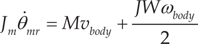
Then, in terms of a dynamic model [42] using Newton's second law where M and J are platform mass and rotational inertia, and Jm represents the motor and gearbox inertia, our dynamic force and torque model for left and right wheel motor torques are then given by Eqns. (7) and (8).
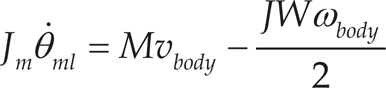
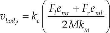
It can be shown that the electrical energy input to the electric motors directly relates to the mechanical energy of the platform. Therefore, losses and ratios can be empirically obtained and their respective sums are represented by constants k. Taking the voltage inputs to the motors as having an almost direct linear relationship to the electrical power, we can then say that the electrical voltage motor inputs to the motors are directly proportional to the respective desired wheel torques of each drive wheel, which in turn are directly proportional to the body velocity and body turn rate expressed in Eqns. (9) and (10).


We can then describe our improved adjustable dynamic model in terms of torque and force damping directly from the obstacle avoidance requirements, as shown in Eqns. (11) and (12), where the obstacle damping force from an obstacle on the front right zone quadrant acts independently on the left wheel F r , and an obstacle on the front left zone quadrant acts on the right wheel F l as exponential ratios. They are bounded by Eqn. (13) such that they drive their respective opposing side-wheel velocities to zero in the presence of obstacles, as previous work by Braitenberg [46] and Nolfi and Floreano [47] demonstrated with their biologically inspired mobile robots.


The damping equations of each motor can be re-arranged to be expressed in terms of the body-heading velocity and body-turning rate: Eqns. (14) and (15).

Following on from the development of the localized potential force field and the platform dynamic model development, we then apply them to the concept of a localized workspace travelling with the platform. Previous work using the VFH [25] and the DWA [26] had identified several problems when the methods were applied to the task of the assistive PWC [24, 34] and we solved these issues with our DLAFF method.
Having undertaken evaluation and experimentation, we propose that a more effective way of modelling the region of interest around the platform, or local workspace, can be expressed in terms of a Euclidean ellipse that has a geometric relationship with the PWC platform's dimensions. This region replaces the histogram workspace with a nonlinear repulsive region around the PWC platform. Similar work on the subject has looked at modelling obstacles such as ellipses to improve the flow of potential field lines [48] and another looked at modelling the obstacles as geometric shapes [49].

Elliptical platform obstacle avoidance model
In our DLAFF model, the inner ellipse represents the physical boundary of the platform and the outer ellipse the furthest extent of the repulsive region. One focus of the inner ellipse and outer ellipse marked in red and shown in Fig. 3 is located at the body-coordinate origin marked ‘o', also shown in Fig. 2, and the other focus of both ellipses is located along the x body axis — the inner ellipse coincides with the front steering axis, the outer ellipse moves outward from the inner focus’ location according to the adjustment of the region of repulsion. Therefore, the inner ellipse shape is determined by dimensions A and B, where 2A is at least the length of the platform (including appendages) and 2B is at least the width of the platform, plus any overhang. The platform sits within the inner ellipse boundary as shown in Fig. 4. The outer ellipse can be extended along Ex and Ey, as shown in Fig. 3, which is always equal to or greater than the inner ellipse's dimensions.
Furthermore, our ellipse model can be separated into zones with different elliptical dimensions depending upon the navigational requirements. For example, the right hand side zone may have the inner and outer ellipse extended along Ey (Fig. 3) to follow a corridor along one side, or for lane following behaviour. Another example would be to extend both the left and right front zones as shown in Fig. 3 along Ex; this extension can be based upon dynamic feedback, so that as velocity of the platform increases then the inner and outer ellipses are extended, not necessarily equally. Therefore, this method allows the repulsive elliptical zone surrounding the platform to be easily tuned to the task at hand, either by some other system or by the user.

Zonal application of the elliptical obstacle avoidance model
Sensors are mounted so as to radiate out from the platform, such that they provide ranging data along the lines marked R and p in Fig. 3 and Fig. 4. The repulsive force field method is applied as a moderating input to the drive motors, as developed in the previous section. This force is applied along the ranging axis R between the inner and outer ellipses, which is given in the general form by Eqn. (16), where the nearest obstacle on each side is specified by the zone such that Eqns. (17) and (18) represent the terms for the front left and right zones; the rear and side zones can be similarly obtained. Fig. 4 shows the front right quarter angle as θ, represent the region covering the maximum platform steering angle (max α) whilst still moving forward or reverse, such that the sensors in this region can be high resolution providing accurate range and angle, for example, in detecting doorway sides. The side zones are used to detect proximity to obstacles, such as walls, when the platform is translating in the x body axis, and obstacles when rotating about the z body axis in the special case of the unicycle or wheelchair kinematic model. Thus, our ellipse model separates obstacles and sensors into zoned regions of interest as shown in Fig. 4; where, depending upon the direction of travel, the nearest object in each zone then acts to damp each drive motor.
The damping terms:


Where: θ ≥ 0 and θ ≤ αmax

Where: θ < 0 and θ ≥ − αmax
The angle α relates to the maximum steering angle of the car-like platform whilst, in forward motion, the term k allows the potential field slope to be empirically tuned.
The zones shown in Fig. 4 are a simplification; the number depends upon the placement of suitable sensors, the type of platform and individual applications. Each zone can be independently manipulated: moving the inner and outer ellipse further out or the outer ellipse closer in (when the inner ellipse is at the minimum range). Furthermore, zones can be active or not, depending upon the requirements. For example, active zones would be related to the direction of platform motion, side zones can be activated when the platform is either rotating about the z body axis or according to the task: such as traversing corridors, when lane following or according to some other dynamic requirement.
The equations for all zones are the same as for the forward one, although the repulsion may be applied to both wheels equally to slow the platform down rather than turn it away. Zones should coincide with angular steering limitations such that no obstacle can be missed. Dynamic adjustment of the force field by velocity feedback or joystick input can be implemented by extending both the inner and outer ellipses by an amount proportionate to the velocity, and/or by adjusting k.
Our experimental platform hardware, labelled in Fig. 5, consisted of a differential drive wheelchair, with a width of 0.68m (2B inner ellipse variable) and a length of 1.0m (2A inner ellipse). The platform was driven by two 150W brushed DC motors, through two 25A independent motor drivers. A Hall Effect joystick and four digital buttons were employed as the human input devices. An Atmel SAM3X8E ARM 32-bit microcontroller was used as the system-processing unit. We modified the two standard motor gearboxes to make each accommodate a 360-pulse resolution optical wheel encoder.
For the movements of wall following and doorway passing, an array of six Sharp GP2Y0A710K0F 5m range infrared distance measuring sensors were mounted on the platform at 90°, 45°, 10°, −10°, −45°, −90°, and two 128-pixels TSL1411 line-scan imaging sensors (one covering the front left zone and the other the front right zone between −25° to 25°) modified to function in the near-infrared, in order to provide a high-resolution obstacle-edge detection for doorway passing. An additional two Sharp GP2Y0A710K0F 5m range infrared distance sensors, together with six sonar SRF02 ultrasonic range finders, were mounted lower down for the detection of obstacles.

Experimental DLAFF test platform
A series of tests were conducted to experimentally evaluate the performance of our DLAFF method:
Trajectory comparison,
Travel down a narrow corridor,
Travel down a wide corridor keeping to one side, i.e., lane keeping,
Approaches to an obstacle at different velocities,
Negotiating several obstacles in the pathway,
Passage through closely spaced obstacles, i.e., a doorway and
Driving up to an obstacle and docking.
An initial trajectory comparison was made between eight naturally driven human trajectories, shown in Fig. 6, and eight paths, shown in Fig. 7, that the DLAFF method generated by negotiating ninety-degree corridor turns. The PWC platform started at the same position each time and was driven by a non-disabled, experienced operator of a PWC. Full joystick control was available for the human trial; however, for the DLAFF trial, only forward velocity was controllable, not turning, and the collision avoidance provided the steering.
When a best-fit quadratic curve is applied to each of the two sets of trajectories, the resulting curves given in Fig. 8 can be seen to be a similar shape.
A 1.1m wide corridor was chosen for the first experiment, and it was only by adjusting the outer ellipse B value that we were able to pass down the centre of the narrow corridor. The trajectory is shown in Fig. 9a, with a platform clearance of 0.21m on either side. Despite moving the joystick from side to side as if to steer the platform deliberately into the walls—the joystick voltage in Fig. 9b shows this action—little deviation from the centre is seen, and no collision with the walls occurred. Furthermore, no oscillations can be seen with this damping method, as is often the case with potential field applications in mobile robotics [37].
Potential fields have been suggested for lane keeping in mobile robotics [33] and we considered this application in our second evaluation with a 1.7m wide corridor. In this experiment, we kept the right zone ellipse equal to the narrow corridor setting, and set the left ellipse zone such that the platform again followed a path parallel to the corridor. However, this time we had a bias to the right and we set the ellipse shape to allow a little free movement so that the platform could move a few centimetres off course: hence, not damping the overall velocity as much as we did in the narrow corridor. The low clearance between the platform and the right wall at the higher velocity was considered uncomfortable for the user and so adjustment to the two ellipses were made to guide the trajectory away from the right wall a little more. The lane-following trajectory can be seen in Fig. 10a and the attempt to vigorously deviate from the lane-following trajectory by moving the joystick from side to side can be seen in Fig. 10b.
We show in this experiment that one of the major problems when implementing potential fields in mobile robotics and passing between close objects can be overcome using our DLAFF method. We adjusted the potential field k to change the shape of the slope in order to reduce the velocity with which the platform passed through the doorway, and minimized the outer ellipse to allow a fast approach.
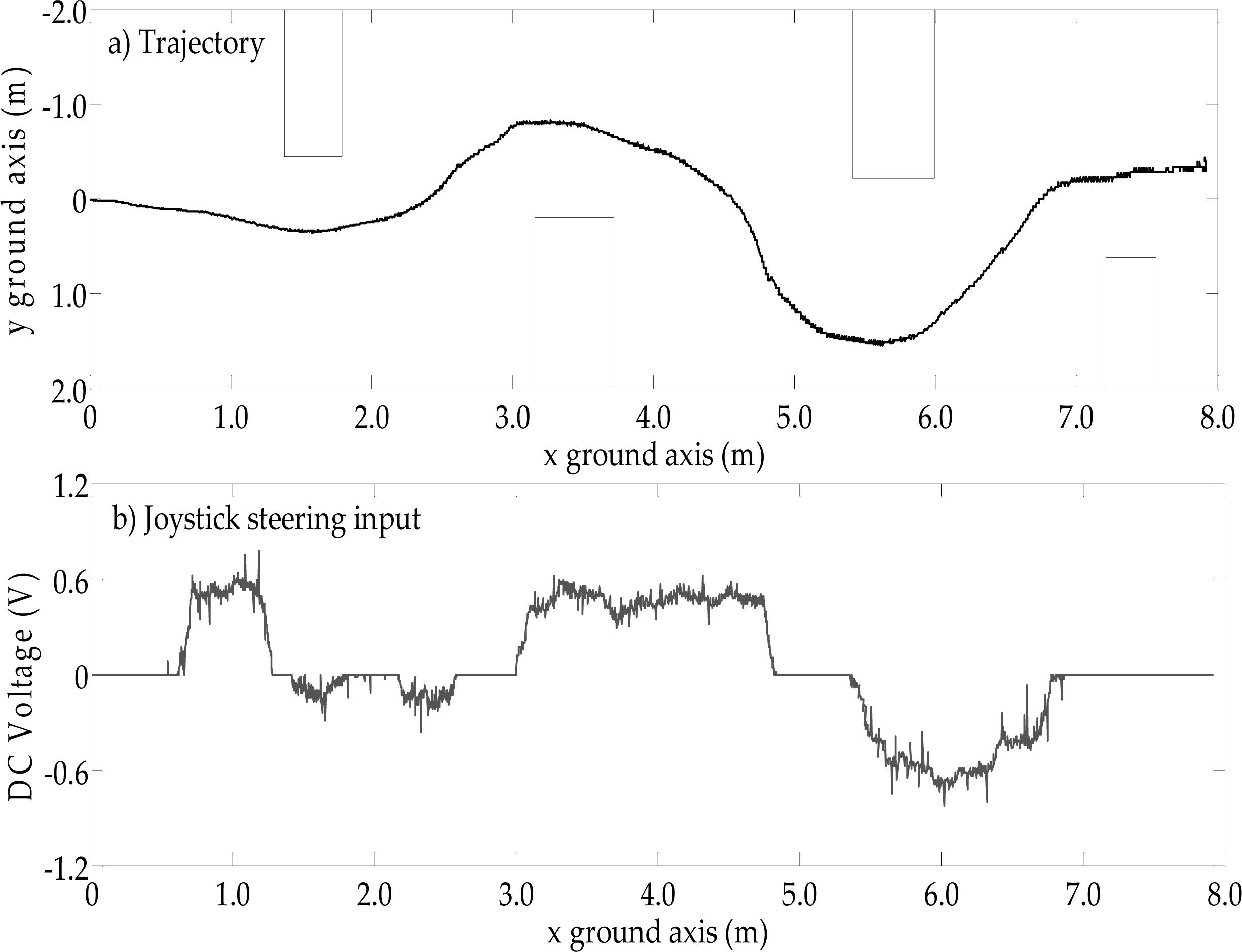
The doorway opening in this experiment was 0.76m; the clearance between the doorway frame and platform was only 40mm each side. The platform trajectory can be seen in Fig. 11a, in which the platform was driven away from the ride side of the doorway, whilst in Fig. 11b, the joystick user input remains at zero. The approach velocity to the doorway is nearly 0.8m/s (Fig. 11b), only slowing and manoeuvring in the last 0.75m; this speed was much faster than was comfortable for the experimenters. Several high-speed passes of the doorway are shown in Fig. 12, where the damping caused the platform to centre on the doorway as it approached. One of the trajectories (6), shown as a dashed line, can be seen to correctly cause the platform to avoid the doorway because the approach angle was too great for the platform to pass through. Hence, our method is not susceptible to the local minima problem [37].
Applying potential field methods to obstacle avoidance has traditionally meant that the repulsive effect of an obstacle may not be sufficiently powerful to cause a deviation of the trajectory until the platform is close to that obstacle; this causes the platform to behave in a non-intuitive manner. Using our DLAFF method, we took the user-desired platform-velocity vector magnitude from the joystick input (which we also treated independently as the force vector) or which we obtained from wheel-encoder velocity feedback, and used that feedback to extend the inner and outer front zone ellipses. This manipulation of the field allows the platform to move out around the obstacle earlier thus leading to a smoother trajectory around that obstacle; at nearly 0.8 m/s, the trajectory starts to deviate 2.5m from the obstacle, as shown in Fig. 13. When we approach the obstacle at a velocity of 0.6 m/s we can see that the trajectory starts to deviate at around 1.5m from the obstacle shown in Fig. 14. Finally if we drive slowly up to the obstacle, in this case <0.2 m/s, then the dynamic potential field allows the platform to be driven very close to the obstacle before diverting the trajectory away from it, as shown in Fig. 15 — such a requirement would be necessary when manoeuvring in highly cluttered and confined environments.

Human-turned PWC trajectories
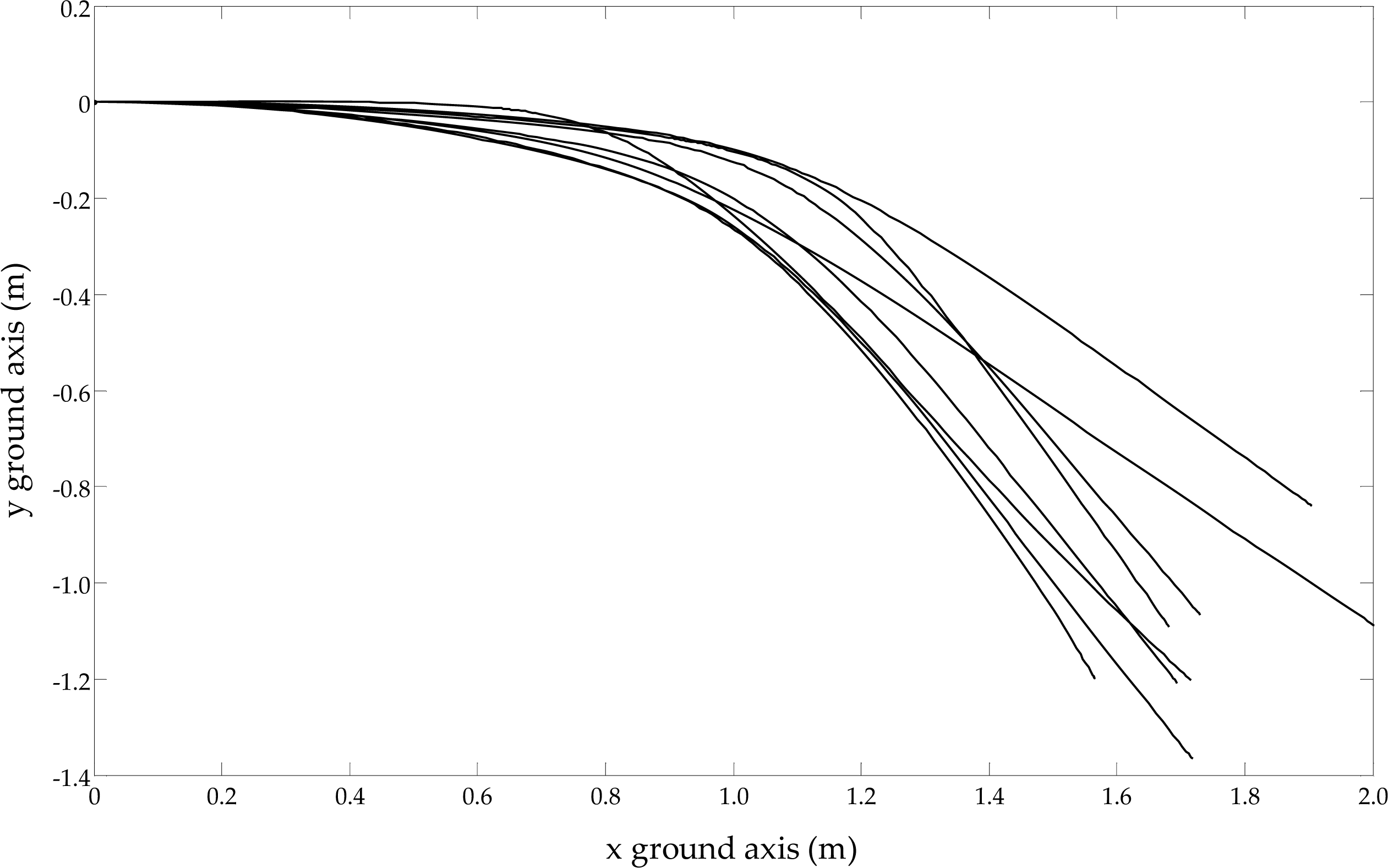
DLAFF collision-avoidance-turned PWC trajectories
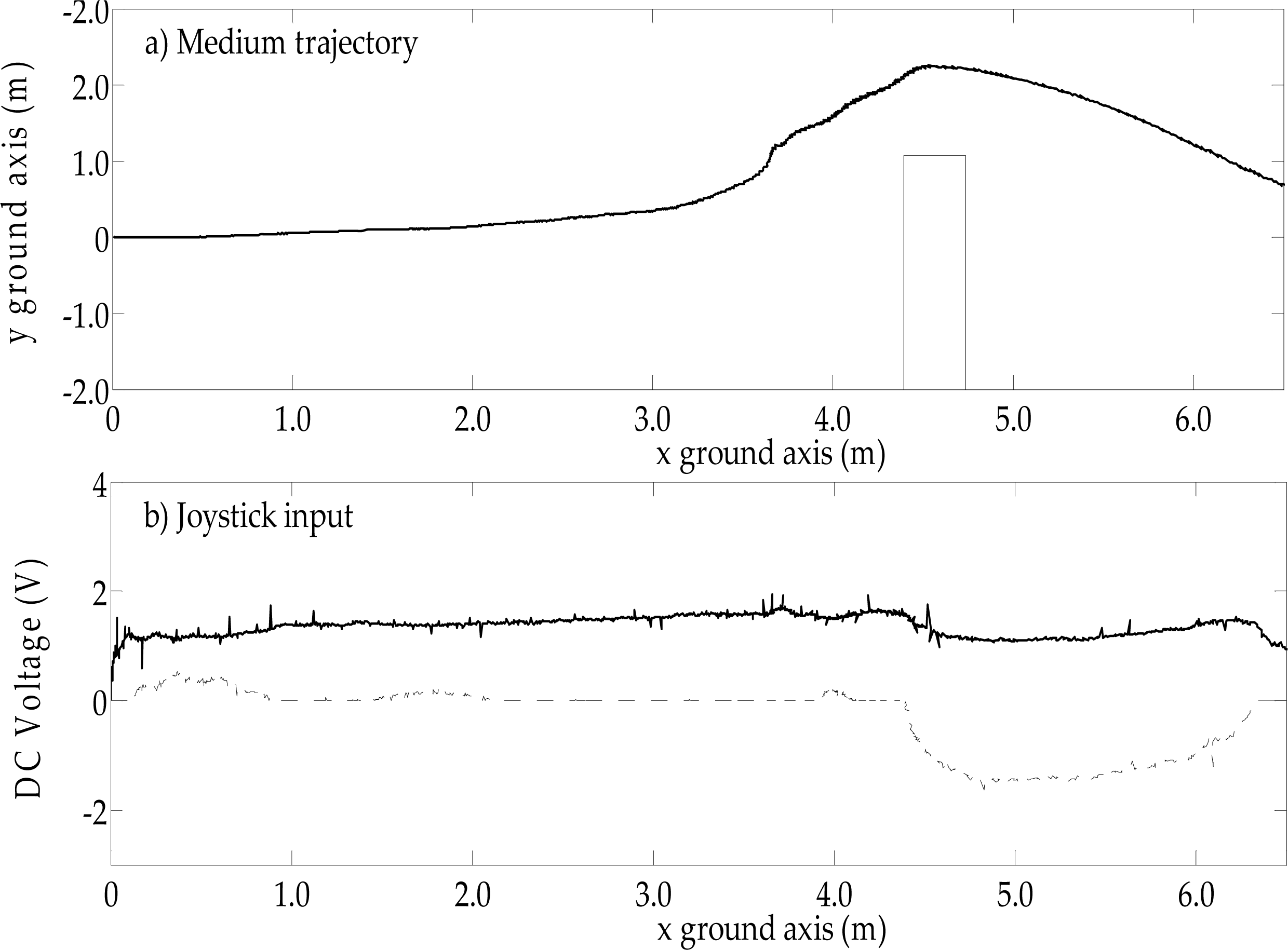
A multiple obstacle experiment was run with four obstacles in order to evaluate the performance of the platform when negotiating slaloms. The obstacles were placed approximately 1.5m apart longitudinally and approximately 0.5m apart laterally. The trajectory can be seen in Fig. 16a and the joystick steering can be seen in Fig. 16b, which shows the input from the user in trying to oppose the motion by deliberately driving the chair into the obstacles.
One inherent problem with obstacle avoidance methods is that by avoiding obstacles, the robotic platform is prevented from docking or passing close by; for example, when a human operator is on that platform, they may wish to pull up to a desk. We solve this problem by using our DLAFF method; our previous experiments have shown that the platform can pass through a doorway and pass close to corridor walls. We have also shown that the method allows dynamic feedback to alter the elliptical potential field. Therefore, in this experiment, we treated the complete frontal zone as the same shape, i.e., no longer handed (the nearest obstacle in either frontal zone acts on both drive wheels, equally) and we used the joystick velocity demand as feedback to adjust both the inner and outer ellipses proportionally.

Best-fit quadratic curve comparison

Passage down a narrow corridor
When we drove up to a wall with a dead-end, the period marked D of the joystick forward-velocity command shown in Fig. 17b can be seen to demand the platform move, yet the period marked S in Fig. 17a clearly shows that the actual platform velocity is zero during this period. It is only after the period D, when the joystick demand is reduced to a very low level that the dynamic damping allows the platform to move forward with a very slow velocity until docking occurs and the demand is zeroed. This experiment clearly shows that our DLAFF method allows the platform to dock gently, and that excessive demand drives the platform velocity to zero, such as a digital switch remaining high, the joystick being accidently stuck in the forward position or operated erratically due to the platform user's motor co-ordination difficulties, for example.
These experimental evaluations were repeated at least 10 times each with different attempts to crash and steer incorrectly; the data shown in each of the figures are representative of one of those tests.
Evaluation of smart PWCs has no associated standard and benchmarks. Driving around a course that may include corridors and doorways while assessing the number of collisions and the time taken is usually adopted as a method of evaluating the performance of an assistive robotic PWC. One trial undertaken in 2002 by Yanco et al. involved 14 non-disabled participants using the Wheelesley platform [50]. When asked to complete an obstacle-strewn course, participants were able to reduce their time taken by an average of 25% when using the assistive system rather than the manual one. Furthermore, the number of collisions was on average reduced from 0.25 using a manual system to 0.18 per person when in assistive mode. The users reported on a scale of 1–10, where 10 represented the best, that the system rated 8.7 and the manual rated 3.5, on average.

Lane-following movement

A fast and incorrect line of attack to the doorway
Another example of assessing smart PWCs is the ARTY project, in which researchers sought to test their smart PWC using eight non-disabled children aged 11 on a simple obstacle course, going forwards and in reverse (2012)[24]. The test consisted of trialling two assisted control modes (safeguarding and assistive) and did not appear to include a non-assisted comparison. Although the assistance was helpful when reversing, the researchers reported little difference in the forwards test. Interestingly, when the respondents were asked after the trial if ‘it felt natural driving the wheelchair', there was little distinction between safeguarding, the assistive method or the use of both together. The researchers went on to test the system with a five-year-old boy who had physical and cognitive disabilities, and who was considered by his occupational therapist not ready to learn how to operate a PWC.
In order to evaluate the human compatibility of the DLAFF methodology using our ACA control architecture, 17 non-disabled volunteers (a similar number of participants to that used by Yanco [50], Soh [24] and Urdiales [51]), with various levels of PWC operation and car-driving abilities, were used to test the platform performance in a controlled obstacle course environment, as shown in Fig 18. They were given simple instructions on how to operate the wheelchair platform safely, told that they would be followed by someone with an emergency power cut-off switch and shown their own easily accessible emergency stop button. The 17 participants were composed of 14 males and three females; unintentionally, all male participants were given the joystick analogue-input device and all female participants used a digital button push-input device.

Various doorway approaches

A fast approach to an obstacle
The participants were all shown the obstacles and walked through the course, the obstacles were all lightweight cardboard and the doorway had collapsible sides that folded back to prevent injuries or any need to stop. The course consisted of a narrow doorway and a series of obstacles, as indicated in Fig. 18. The task consisted of each individual completing 12 consecutive circuits, the first two with assisted navigation on, then the next two without assistance, and so on. The subjects were all notified of the status of the assistance and data were collected by the system with regard to the amount of deflection given by the system assistance to the user's trajectory when passing through the doorway.
A medium velocity approach to an obstacle

low velocity approach to an obstacle
All participants were asked to complete a questionnaire (see Appendix): the first page 1, up to and including question A, before the testing, and the remainder of the questions afterwards. This questionnaire contained a section based upon the NASA task-load index [52], which aimed at checking that the participants had followed the instructions given to them in completing the task.
The NASA Task Toad Index workload evaluation procedure is usually a two-part procedure that requires collecting an individual's rating and a weighting of each of the six perceptive categories:
Mental Demand (MD),
Temporal Demand (TD),
Performance (P),
Frustration (F),
Effort (E) and
Physical Demand (PD).
Obstacle slalom

Dead-end or docking
These perceptive responses are quantified into a 0 to 20 scale which is then used to produce an Overall Workload score; this method has been used for over 20 years in many diverse applications [53]. We have chosen to use this method for the purposes of checking for consistent testing. We informed the participants that they should circumnavigate the course, starting and stopping at the same place with the following strict caveats:
Repeat the same path accurately, each time,
Treat this test as if it were a driving test,
Attempt your best competitive effort,
No stopping,
Avoid all collisions and
Complete each circuit as fast as possible.
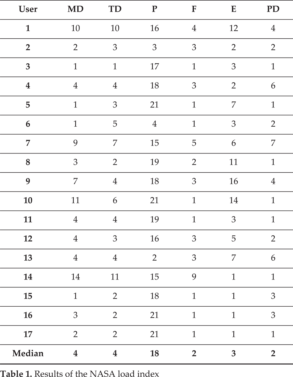
Having preloaded the task, it was felt unnecessary to use both parts of the NASA Task Index; therefore, only the first part was applied. The results are given in Table 1 which shows that the participants did abide by the caveats, that the tester did not guide the completion of the form and that some of the outliers were caused because the participants did not fully understand the context of the question — some thought that ‘effort’ applied to their attempts to follow the caveats rather than to the difficulty of the actual task. Similar confusion occurred with four individuals with regard to the mental demand and the temporal demand that they, again, believed referred to driving the wheelchair rather than to the task.

Obstacle course
Results of the NASA load index
Perception results of the participant questionnaire

The participant questionnaire given before and after questions was devised to assess the expectations of the participants towards the collision-avoidance system. They were shown the course and the task was explained with a demonstration. Then, just prior to starting the task, participants were asked to respond on a scale of 1 to 5 how well they expected the system and themselves to perform in completing that task. Having completed the task, they were asked to respond again with their revised response to the task, and how well they and the system performed.
Trajectory assistance when passing through a doorway

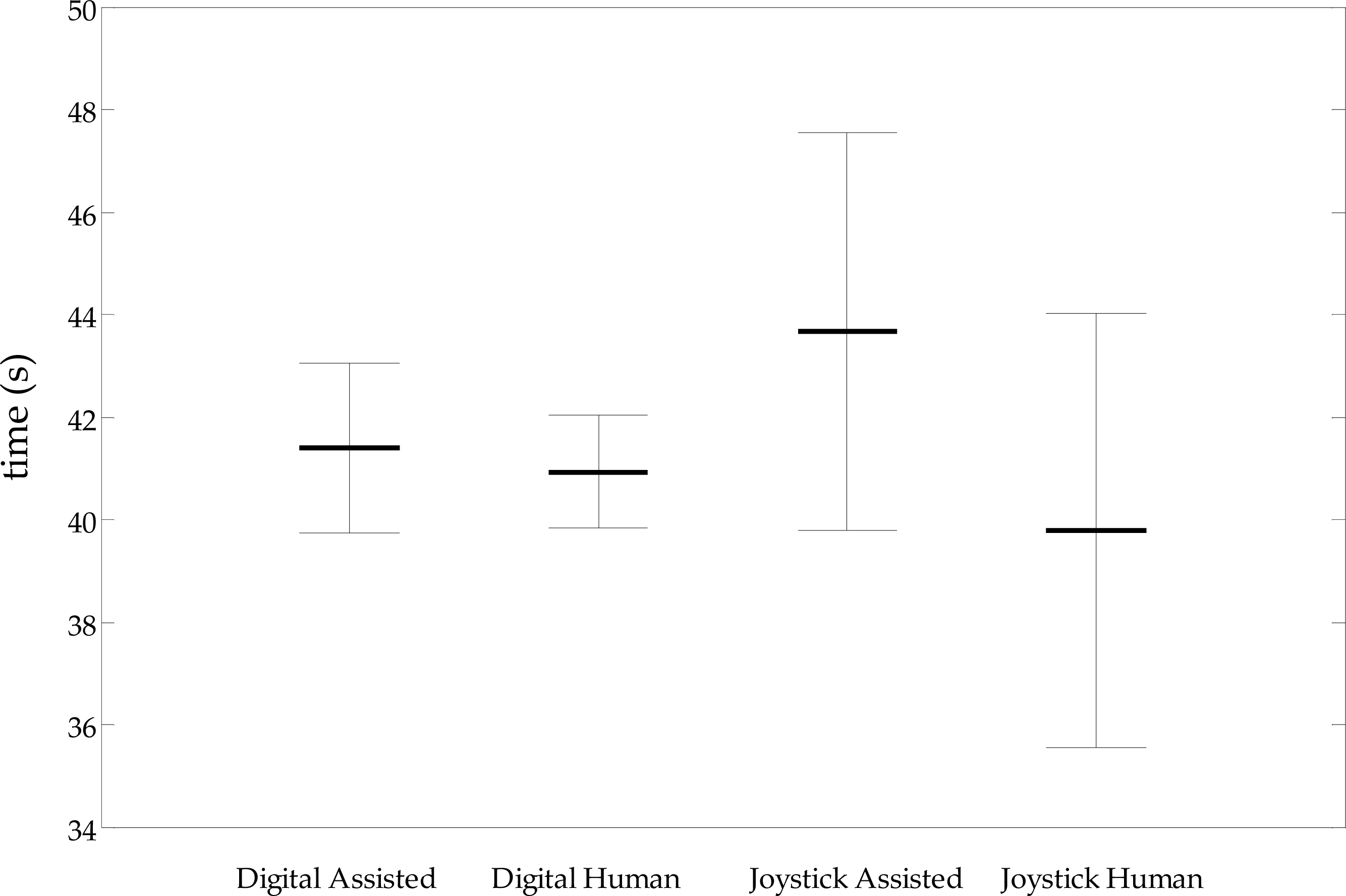
ANOVA results of the obstacle course lap times
The results of the personal perceptions are given in Table 2, which shows that the mean personal rating after (PRA) is higher than the mean personal rating before (PRB), with only two individual's down-rating themselves. The mean system ratings after (SRA) were also higher than the system ratings before (SRB), with no down-rating by any individual. The last column (E) in Table 2 represents the results of participants being asked how obvious, quantitatively speaking, were the system's interventions. All participants were asked whether the intervention was intuitive and was it helpful, to which they all replied that it was. The first column (A) in Table 2 indicates the participants’ previous experiences of wheelchair driving and may be used to qualify the answers given.
There were no collisions with the doorway in all 84 of the passes that the 17 participants made when the assistance was enabled, as shown in Table 3. However, there were four joystick-input participants who each collided once with the doorway during the 84 passes without assistance. One of the three digital-input participants collided on three of their six passes without assistance. The doorway-passing trajectory assistance for each participant was recorded and given again in Table 3. The three digital-input participants (15–17) consistently received the most assistance, as would be expected; the other 14 analogue-joystick-input participants ranged from a good central alignment with no help (Participant 13 on Pass 1) to one participant who decided to test the system by trying deliberately to crash (Participant 1 on Pass 5), which required the system to intervene more.
Previous research has determined that ANOVA is a suitable tool for assessing the statistical differences between assisted PWC driving and non-assisted. The aim of the human trial was to establish whether the DLAFF method and the ACA control architecture was intuitive and less frustrating than other assistive PWC methods. There were 84 timed laps with the system on and 84 laps with the system off, undertaken by participants using a human joystick-input device. The statistical ranges shown in Fig. 19 give a p-value of 0.23 for joystick users, indicating that there is not a significant statistical difference between assisted and non-assisted lap times. When the 36 digital-human input lap times were analysed, the p-value rose to 0.94, which is statistically significant. The assistive system with digital input had no collisions and no statistical lap-time reduction when compared to the non-assisted lap-times, which had three collisions. As a check, the p-value for the participant who had the three collisions was 0.98, which indicates that no time was expended due to the collisions.
Previous experiments by Ferrer et al. [54] using a modified VFH method indicated that oscillations occurred and, on evaluation, that user frustration was higher when the assistive system was engaged. Soh and Demiris also reported that VFH was difficult to tune and that they were unsure of the behaviour [24].
A novel, enhanced, human-in-the-loop control structure has been presented that allows the human-in-the-loop to provide guidance commands on a higher level than is possible in a traditional system, whilst retaining the role of instigator of all actions. The system incorporates a localized adjustable elliptical force field that can be used to overcome the traditional problems associated with potential field methods. This method is applied to a novel-shaped dynamic window that travels with the platform; this shape allows the platform trajectory to obey an appropriate set of kinematic constraints.
The paper demonstrates through human evaluation that:
when users try to pass through a narrow standard doorway using a powered wheelchair, collision will occasionally occur for some users when not provided with assistance;
our collision avoidance method prevents collision with narrow doorways and will not allow passage if the approach angle is such that the gap is too small, yet it does not suffer from the local minima problem;
the assistive trajectory is similar to the humans’ natural trajectory;
from the user feedback, our DLAFF method of assistance is intuitive and not intrusive when the user needs that assistance;
oscillations around objects and in narrow corridors do not occur when using our method;
trajectory deviation can be adjusted according to the dynamics of the platform, or obstacle.
The lap time analysis indicates that the collision avoidance method does not slow down a joystick-input powered-wheelchair user with any degree of statistical significance. Regarding digital input, a method that many highly disabled powered-wheelchair users may need to use, lap time analysis showed that when comparing the non-assisted laps to the assisted ones, there was a statistical significance that they were equal. In addition, all the assisted laps were collision free as opposed to the case of the non-assisted laps. One user who had three collisions with the doorway had almost identical lap times; the statistical significance between assisted and non-assisted laps was p = 0.98.
We therefore conclude that the DLAFF method is potentially suitable for application in human-in-the-loop systems, such as assistive mobile robotic wheelchairs and tele-operated robots; future work will be required to test the method in human clinical trials.
Footnotes
8.
This research was supported by the European Union Interreg IVA “2 Mers Seas Zeeën” cross-border co-operation programme (2007–2013) under the SYSIASS grant.
Appendix A
Explain the purpose of the trial and the test procedure:
To drive the wheelchair, via the joystick, from the start position around an obstacle course, through a narrow doorway and back around to the start position, as quickly as possible, without any collisions, stopping, or reversing. This should be repeated 12 times, the first two attempts with the system off, the second two attempts with the collision avoidance system on, and so on until all circuits are completed.
…………………………………………………………
…………………………………………………………
Notes: To complete section A during/after trial, and section B after trial without the participant seeing their score or being told any feedback until after recording data.