
Abstract
A hybrid tactile sensor system is proposed for a robot hand to hold and grip an object adaptively as the sensor system measures the slip of an object, the gripping force, and the deformation of its silicon rubber sensor element. A hybrid tactile sensor system consists of a Carbon Micro-Coil (CMC) touch sensor and a force sensor. The CMC sensor element is made of silicon rubber containing CMCs several micrometres in diameter. It is considered that the sensor element constitutes an LCR circuit, and the CMC touch sensor, deformed mechanically, produces signals due to the modification of the circuit. In this study, a dome-shaped CMC sensor element similar to the shape of a human fingertip was used. This paper first examines the characteristics of the CMC sensor in terms of slip detection when the sensor system held and released an object. Next, the characteristics of the CMC element are clarified with respect to the compression force and deformation when the CMC element was compressed vertically. Finally, methods using the hybrid tactile sensor system are developed to detect the slip of an object and estimate the magnitude of deformation of the CMC element.
Keywords
1. Introduction
Robots are expected to support human activities in an office or at home, as well as working in a factory. To develop those robots, sensor systems such as the vision and tactile sensor system are considered to be one of the most important devices in a robot. Although a CCD camera has been utilized as a useful sensor system for a robot, it seems that a practical tactile sensor system that can be easily mounted on a robot finger has not yet been developed.
In contrast, human tactile sense is a very useful sensory system. For example, humans can usually hold and operate an object with their fingers as they apply just enough gripping force to prevent the object from slipping. This is possibly because they use their tactile sense to measure the force and deformation of their fingertips simultaneously. Especially since human tactile sense is highly sensitive in order to measure the force variance of gramme order and the fine deformation of micrometre order, humans can employ the information to control the gripping force appropriately just before and after the gripped object starts to slip.
Some researchers have already developed tactile sensors to measure force and/or deformation applied to a sensor element [1–3], as well as slip of an object [4]. The optical three-axis tactile sensor [5, 6] is composed of several columnar feelers made of silicon rubber. The haptic sensor developed using GelForce technology [7, 8] utilizes a transparent rubber as a sensor element. These sensors can measure the magnitude and direction of a force by capturing the deformation of the sensor element. In addition, the slip-detecting tactile sensor [9, 10] consists of thin pressure-conductive rubber sandwiched between two conductive film sheets, and the sensor can detect the slip of an object touching it.
A Carbon Micro-Coil (CMC) touch sensor [11–13] is also known to be a highly sensitive tactile sensor. A CMC is a coil of micrometre size made of carbon. The length of the CMC used in this study is around 90 μm and its diameter is around 10 μm. The sensor element is made of silicon rubber containing CMCs. A CMC touch sensor is capable of responding to stimulation of micrometre order. A CMC sensor element simply consists of silicon rubber and electrodes for input/output sensor signals, and it is easily moulded into a shape similar to that of a human fingertip. Compared with the above-mentioned sensors, the CMC touch sensor is considered more suitable for an easy-to-mount tactile sensor on a robot fingertip.
In [14], the authors proposed a hybrid tactile sensor system consisting of the CMC touch sensor and a force sensor, and they developed a method of measuring the magnitudes of force and deformation of the sensor element using a CMC sensor element moulded into a square of side 30 mm, 3 mm thick. In this study, making a dome-shaped CMC sensor element enables the sensor system to be mounted on a robot hand.
In this paper, to develop a tactile sensor system for a root hand that can hold and grip an object adaptively as a human can, the characteristics of the CMC sensor in terms of slip detection when the hybrid sensor system holds an object are investigated. In the experiment, the outputs of a CMC sensor and a force sensor are sampled when an object that is held by the CMC sensor element slips. Next, to clarify the characteristics of the CMC element with respect to the compression force and deformation when the CMC element is compressed vertically, the relationships between the output of the force sensor, the compressive deformation of the CMC element, and the fine deformation of micrometre order of the CMC element are measured. Finally, to evaluate the performance of the hybrid sensor system with a dome-shaped sensor element, experiments to detect the slip of a gripped object using the CMC sensor's outputs and to estimate the compressive deformation and fine deformation of the sensor element using the force sensor's outputs are conducted.
2. Hybrid Tactile Sensor System Consisting of Dome-shaped CMC Sensor and Force Sensor
The hybrid sensor system proposed by the authors consists of a CMC touch sensor and a force sensor. The sensor system is two-layered. The concept of the sensor system is illustrated in Fig. 1. In the hybrid sensor system used in this paper, a dome-shaped CMC sensor element (Fig. 2) is placed on the force sensor. A CMC sensor element is made of silicon rubber (Wacher Asahikasei Silicone Co., Ltd.; ELASTOSIL M4400), moulded into a shape of a dome 16mm in diameter and 4 mm in height, such as a human fingertip. The hardness of the silicon rubber is Shore A23. It contains 10% CMCs by weight, uniformly distributed throughout the sensor element. The CMC touch sensor can respond to stimulation in the order of several micrometres.

Concept of a hybrid tactile sensor system
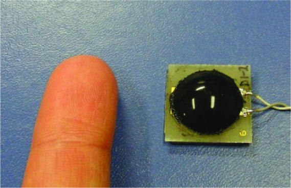
Dome-shaped CMC sensor element
CMCs in the sensor element serve as inductance, capacitance and resistance, while silicon rubber is dielectric and the sensor element is considered to constitute an LCR circuit. When the sensor element is deformed mechanically, the sensor signal processing device (CMC Technology Development Co., Ltd.) detects its impedance changes in the characteristics of the LCR circuit by measuring the modulation of amplitude and phase of an input excitation signal to the sensor element. The device also creates voltage signals of the R- and LC-components separately according to the amplitude and phase modulation.
The hybrid sensor system has the ability to measure deformation of the sensor element as well as force applied to it. When a robot equipped with the sensor system grips an object, not only the compression force in gripping the object but also the compressive deformation of the fingertips can be measured. In addition, as this paper describes, the sensor system can detect the slight deformation of the fingertips which occurs just before and after the gripped object starts to slip. Consequently, it is expected that a robot equipped with the sensor system holds and grips an object without dropping it and operates as adaptively as a human can.
3. Detection of Object's Slip Using Hybrid Sensor System
3.1 Experimental Apparatus with Hybrid Sensor System
As shown in Fig. 3, a measurement system was developed that uses a CMC touch sensor, a force sensor and a laser displacement meter to measure the characteristics of a CMC sensor in terms of an object's slip detection. This measurement system consists of a CMC touch sensor (CMC Technology Development Co., Ltd.), a six-axis force sensor (BL. AUTOTEC, Ltd.), a laser displacement meter (KEYENCE), and positioning stages (Kohzu Precision Co., Ltd.). The force sensor's resolutions of X-, Y-, and Z-axes are 2 gf, 2 gf, and 6 gf, respectively. The stage resolution is 0.5 μm/step. One of the dome-shaped rubber elements is a CMC sensor element including CMCs, and it is placed on the force sensor. The positioning stages driven by the stepping motors push the rubber elements against an object to grip it. The force sensor measures the X, Y, and Z-axis forces when the system holds an object; the laser displacement meter measures the vertical slip of the object when the system releases the object. In this experiment, the sensor outputs of the CMC touch sensor, force sensor and laser displacement meter are sampled simultaneously when the dome-shaped rubber elements hold and release an object.

Experimental apparatus with a hybrid sensor system for griping an object
3.2 Outputs of Hybrid Sensor System in Releasing an Object
In this experiment, to clarify the characteristics of a CMC sensor in terms of an object's slip detection, the CMC sensor's output, force sensor's output, and laser displacement meter's output are measured when the system holds an object at the initial gripping force of 1 N and releases it at the velocity of the stages of 0.1 mm/s. The object is a rectangular, plastic box (22 mm • 45 mm • 90 mm, 29 gf).
Figure 4 shows the outputs of the force sensor and laser displacement meter. The horizontal axis expresses the time while the left-side vertical axis expresses the force sensor's output. The right-side vertical axis expresses the amount of slip of the object measured by the laser displacement meter. The Z-axis force (gripping force) decreases from −1 N to −0.2 N as the system releases the object, although the Y-axis force remains almost constant close to zero and the X-axis force changes slightly. The slip has suddenly occurred at about 4.9 sec and the amount of slip increases drastically. Therefore, it is considered that the object started to fall at that time.

Outputs of force sensor and laser displacement meter in the process of holding and releasing an object
Figure 5 shows the outputs of the CMC sensor and laser displacement meter. The horizontal axis expresses the time while the left-side vertical axis expresses the CMC sensor's output. The right-side vertical axis expresses the amount of slip of the object. The voltages of the R- and LC-components of the CMC sensor increase gradually as the Z-axis force decreases as in Fig. 4; then, the CMC sensor's outputs drastically change when the object starts to fall. As a result, it is found that the CMC sensor can detect the slip of an object gripped by the sensor elements. Therefore, a method of slip detection will be developed to enable a robot hand equipped with the CMC sensor to grip an object.

Outputs of CMC sensor and laser displacement meter in the process of holding and releasing an object
Figure 6 shows the differences in the outputs of the CMC sensor. Each value means the difference between the output voltages of the CMC sensor that were measured at the interval of 0.01 sec. The horizontal axis expresses the time while the left-side vertical axis expresses the difference in the output of CMC sensor. The right-side vertical axis expresses the amount of slip of the object. We can see that the differences of the R- and LC-components change considerably just before the object slips down. Therefore, it is considered that if an optimum threshold of output difference is determined for detecting the slip of an object, a robot equipped with the CMC sensor can possibly hold an object at the suitable magnitude of gripping force without dropping it.

Differences in the outputs of CMC sensor in the process of holding and releasing an object
3.3 Experiment of Object's Slip Detection Using Hybrid Sensor System
This experiment, using the experimental apparatus shown in Fig. 3, investigates whether robot fingers with the hybrid sensor system can detect the slip of an object and keep holding it without dropping it. The rubber elements hold an object at the initial gripping force of 0.5 N and release it at the velocity of the positioning stages of 0.1 mm/sec. The threshold of the difference of the CMC sensor's output is set to ±0.05 V for detecting the slip of an object. When the value of the output difference crosses the threshold, the rubber elements are pushed against the object at the velocity of the stages of 3 mm/sec and the experimental apparatus tries to keep holding the object.
Figure 7 shows the outputs of the force sensor and laser displacement meter. The Z-axis force (gripping force) decreases as the rubber elements release the object. When the CMC sensor detects the slip of the object at about 4.2 sec, the rubber elements are pushed against the object to hold it and the values of the force sensor change drastically. After the experimental apparatus has gripped the object, the output of the laser displacement meter and the Z-axis force of the force sensor keep indicating −1.6 mm and about −0.5 N, respectively. This means that the object slipped down by about 1.6 mm and was still held by the rubber elements. Fig. 8 shows the outputs of CMC sensor and laser displacement meter measured simultaneously. In the additional experiment, it is confirmed that if the positioning stages stopped when the difference of the CMC sensor's output crossed the threshold, the object between the rubber elements fell down slowly and gradually. The result suggests that the CMC sensor can measure the slip of an object touching the sensor element.

Outputs of force sensor and laser displacement meter in the process of holding, releasing, and gripping an object

Outputs of CMC sensor and laser displacement meter in the process of holding, releasing, and gripping an object
4. Measurement of Force and Deformation of CMC Element Using Hybrid Sensor System
4.1 Measurement System of Characteristics of CMC Element in terms of Force and Deformation
In the study, a measurement system (Fig. 9) was developed that measures the characteristics of a silicon rubber element including CMCs (hereafter CMC element) in terms of force and deformation. This measurement system consists of a six-axis force sensor (BL. AUTOTEC, Ltd.) and a wedge-type Z stage (Kohzu Precision Co., Ltd.). The force sensor's resolutions of X-, Y-, and Z-axes are 2 gf, 2 gf, and 6 gf, respectively. The stage resolution is 0.125 μm/step. A CMC element is placed on the force sensor. The Z stage pushes the CMC element against the fixed acrylic plate perpendicularly, causing the compressive deformation and the fine deformation of micrometre order to the element. The force sensor samples compression force when the Z stage applies vertical compression to the element.

Measurement system of the characteristics of a CMC element in terms of force and deformation
4.2 Characteristics of CMC Element in terms of Force and Deformation
In this experiment, a dome-shaped CMC element is used. The force sensor measures compression force when vertical compression is applied to the CMC element and when the CMC element is subjected to fine deformations of 1, 3, 5, 7, and 9 μm in addition to the vertical compression.
Figure 10 shows the relationship between the output of the force sensor and the compressive deformation of the CMC element. The horizontal axis expresses the compressive deformation while the vertical axis expresses the compression force. The compression force increases as the compressive deformation increases, and it is found that the magnitude of the compressive deformation of the CMC element can be estimated using the output of the force sensor.

Relationship between the compression force and compressive deformation of the CMC element
During the experiment, the force sensor samples differences in the output of the force sensor. The results are shown in Fig. 11. Each value means the difference between the force sensor's outputs before and after each fine deformation is applied to the CMC element. The horizontal axis expresses the compression force while the vertical axis expresses the difference in the output of the force sensor. Each mark represents the difference in the output for a constant, fine deformation and for compression forces in the range of 0 to 34 N. It seems that the differences in the output of the force sensor for fine deformations gradually increase as the compression force increases. It is found that the difference in the output of the force sensor for a constant, fine deformation is variable depending on the amount of the compression force.

Differences in the output of force sensor for the fine deformations of 1 to 9 μm
Although the output of the force sensor for a constant, fine deformation varies with variations in compression force, it seems that differences in this output for fine deformation increase linearly when the compression force is kept constant as fine deformation increases from 1 to 9 μm. Therefore, the relationships between the difference in the output of the force sensor, fine deformation, and compression force are obtained in Fig. 12. The horizontal axis represents the difference in the output of the force sensor while the vertical axis is the fine deformation. The relationship between difference in the output of the force sensor and fine deformation is almost linear when the amount of the compression force is kept constant, and the amount of fine deformation can be estimated using the output of the force sensor if the amount of compression force is determined simultaneously.

Relationships between difference in the output of the force sensor, fine deformation, and compression force
4.3 Estimation of Deformation of CMC Element
In this experiment, using the force sensor's output, the magnitudes of compressive deformation and fine deformation of CMC element are evaluated. Figure 13 shows the relationship between the values of the compression force and the compressive deformation obtained in the previous experiment. The compression force is within the range of 0.8 to 34 N; the compressive deformation is within the range of 500 to 1300 μm. Figure 14 also describes the values of gradient of the approximate lines that were shown in Fig. 12. The gradient of line decreases gradually as the compression force increases from 2 to 34 N. Consequently, we can determine the gradient of line for compression force and calculate the fine deformation of the CMC element using the difference in the output of the force sensor.

Compressive deformation of CMC element for the compression force within the range of 0.8 to 34 N

Gradient of the approximate lines for the compression force within the range of 2 to 34 N
To estimate the magnitudes of compressive deformation and fine deformation of CMC element, the equations are determined as follows:


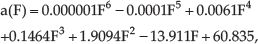
where F, ΔF, Dcomp., and ΔDfine are the output of the force sensor (compression force), the difference in the output of the force sensor (variance of compression force), the estimated compressive deformation, and the estimated fine deformation, respectively.
Next, an experiment is conducted to evaluate the magnitudes of compressive deformation and fine deformation of the CMC element using Eqs. (1) to (3). The measurement system (Fig. 9) is used as an evaluation system. Fine deformations of 1, 3, 5, 7, and 9 μm are applied to the CMC element in addition to compression forces of 1.3 to 10.5 N. The force sensor samples the compression force F and the variance of compression force ΔF before and after the fine deformations are applied to the CMC element. From the force sensor's outputs, the magnitudes of compressive deformation Dcomp and fine deformation ΔDfine are estimated using the equations.
Figure 15 shows the estimated values of compressive deformation. The horizontal axis expresses the given compressive deformation to the CMC element while the vertical axis expresses the estimated compressive deformation. The dotted line means that the values of the two compressive deformations are equal. The marks seem to be distributed near the line. Therefore, it is considered that the hybrid tactile sensor system can measure the magnitude of compressive deformation of the CMC sensor element within the range of 550 to 900 μm.

Estimated values of compressive deformation
Also, Fig. 16 describes the estimated values of fine deformation. The horizontal axis is the compression force while the vertical axis is the estimated fine deformation. The dotted lines mean fine deformations of 1, 3, 5, 7, and 9 μm. The marks of fine deformation within the range of 1 to 9 μm seem to be located near the lines regardless of the magnitude of the compression force. Therefore, the result suggests that the hybrid tactile sensor system can estimate the magnitude of fine deformation of the CMC element.

Estimated values of fine deformation
5. Conclusion
In this paper, a method was developed for a hybrid tactile sensor system to measure the magnitudes of force and deformation in a dome-shaped CMC sensor element made of silicon rubber. Also, it was found that, in a robot hand, the sensor system can detect the slip of an object held by the hand.
First, the outputs of the CMC sensor and the force sensor were measured when an object held by CMC elements slipped. Also, an experiment on CMC elements keeping an object held was conducted. The CMC sensor detected the slip of the object using the values of difference in the sensor's output, and the object remained held without falling.
Next, the characteristics of the dome-shaped CMC element in terms of the compression force and deformation were investigated. The relationship between the compression force and the compressive deformation in the CMC element, as well as the relationship between the difference in the force sensor's output and the fine deformation in the CMC element were also determined.
Finally, the hybrid tactile sensor system evaluated the compressive deformation and fine deformation in the CMC element when force variances in addition to compression forces of 1.3 to 10.5 N were applied to the CMC element. The compression force and the force variance were estimated as the compressive deformation within the range of 550 to 900 μm and the fine deformations within the range of 1 to 9 μm, respectively.
Footnotes
6. Acknowledgements
The authors would like to thank Kenji Kawabe (President of CMC Technology Development Co., Ltd.) for enabling the use of the CMC touch sensor.