
Abstract
Octafilar helical antenna (OFHA) is proposed for handheld ultra-high-frequency (UHF) radio frequency identification (RFID) reader. The investigated antenna configuration consists of OFHA placed on reader device in the presence of human hand model. The antenna is designed at UHF band centered at 915 MHz. The antenna return loss, axial ratio, gain, co-polarized and cross-polarized field components are calculated using the finite element method (FEM) and compared with that calculated by finite integration technique (FIT) for verification of the simulated results. A comparison between the performance of the quadrifilar helical antenna (QFHA) and the octafiliar helical antenna (OFHA) designed at 915 MHz in the presence of the reader device and human hand model is investigated. The OFHA introduces high gain, high front to back ratio, good axial ratio and omnidirectional coverage.
1. Introduction
In recent years, radio frequency identification (RFID) in the UHF band (860–960 MHz) has become popular in many applications. These applications include supply chain management, serving the needs of manufacturing, distribution and shipping [1]–[3]. RFID technology is used for automatically identifying and tracking objects offering best tradeoffs between read range, cost, and size. The RFID system generally consists of the reader, tag, and the system operates in the UHF band. The RFID reader antenna is an important component in RFID system and has been designed with circularly polarized (CP) operation. A CP antenna with a low profile, small size, lightweight, high gain, and high front-to-back ratio is required in a portable RFID reader [4]–[6]. Antenna with higher gain helps to increase read range for the same transmitted RF power, or equivalently one can decrease the transmitted power to achieve the same range. In compliance with maximum allowed 4W or 2W effective isotropic radiated power (EIRP) for microwave RFID systems, the latter option is perhaps more valuable as it implies lower power consumption by the transmitter and thus longer battery life.
Handheld antennas are likely to be close to human body. Therefore, for the associated health issue, the high front-to-back ratio can prevent users from exposure to the handheld application. Commercial handheld RFID readers use patch antenna where circular polarization is desired [7, 8]. The patch antennas are narrow bandwidth. The radiation pattern of a patch antenna has peak gain at boresight (directly in front of the antenna) which is not always ideal in RFID applications where an RFID reader antenna is centered above the coverage area. Resonant quadrifilar helix antenna (QFHA) and more recently the printed quadrifilar helix antenna are used extensively in satellite communication and GPS applications [9]. Generally, for the QFHA the bandwidth of the antenna is related to the size (in wavelengths) of the cylindrical envelope containing the radiating elements, with the volume and diameter being important parameters. The advantages of this antenna are its cardioids pattern, circular polarization and relatively small size compared to other antennas. In UHF RFID, small low gain helical antennas have been primarily used in their normal mode for readers [10]. A relatively recent work describes the potential use of axial mode helical antennas for readers, but the size and construction of those antennas were impractical for handheld readers [11]–[13]. A circular polarized QFHA for UHF RFID reader is introduced in [14, 15]. Octafiliar helical antenna (OFHA) was used for mobile satellite handset communication in [16, 17]. This paper describes the design of a printed OFHA with uniquely shaped radiation pattern to increase the coverage area. The printed OFHA offers advantages of light weight, low cost, circularly polarized, good axial ratio and omnidirectional radiation pattern. It doesn't need a ground plane, and the environment in the area underneath the OFHA has a relatively small effect on the radiation characteristics.
The antenna is modeled and analyzed using the finite element method (FEM) and the results are verified by that calculated by the finite integral technique (HT). In this paper, the finite element method (FEM) is used to solve Maxwell's partial differential equations describing an electromagnetic problem subject to proper boundary conditions. The entire volume of the problem is discretized into a large number of tetrahedral which is called the tetrahedral mesh or the finite element mesh. At the vertex of each tetrahedron, the field components tangential to the three edges at each vertex are stored. The normal vector field at the midpoint of the edges is also stored. These stored values are used to estimate the electric and magnetic fields inside the tetrahedral. Maxwell's equations are formulated from the field quantities in the tetrahedral and transformed to matrix equations that are solved by numerical methods. A denser mesh of small discretizations could be used for more precise solution [18, 19].
The Finite integration technique (FIT) with the perfect boundary approximation (PBA) is a generalization of the Finite-Difference Time-Domain (FDTD). In this method, the integral form of Maxwell's equations in time domain is discretized instead of the differential ones. The PBA mesh has excellent convergence properties. The simulation doesn't require a huge memory to be carried out. Accordingly, using the PBA mesh is suitable to simulate the large structures as the simulated results can be obtained in a very short time [20, 21]. Comparing the PBA with the staircase mesh and the tetrahedral mesh, it is considered the best one in terms of the low memory requirements. The tetrahedral mesh also has excellent convergence properties but it requires large memory and a long computing time if large structures are to be simulated. As for the staircase mesh, it is suitable for simple structures without curved structures as it will not converge in a reasonable computing time. The paper is organized with Section II describes the modeling and construction of the OFHA as part of the reader structure. Section III presents and discusses the simulation results. Finally, Section IV concludes the results in the paper.
2. Numerical Results
The OFHA consists of four identical bifilar helices arranged coaxially with 45° degree separation to each other in space. Fig. 1a shows the structure configuration of half-turn OFHA. One arm of the OFHA called bifilar consists of two diagonally opposite thin strips wound around circular cylinder and form two identical helical elements connected radially at the top. A bifilar element comprises a continuous conductor which is open at the radial center of the bottom end. The two open conductor ends provide the feed terminals for the helix. The rectangular coordinates of any arbitrary point on the bifilar element are given by [19]

The construction of Octafilar helical antenna (OFHA) in free space.
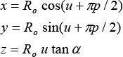
where p=0 and p=2 for two helix arms, u is the angle measured from the x-axis, started from u=0 and ended at u=2πN, N is the number of turns. Ro is the helix radius. For one turn helix C is the circumference (2π Ro), and the spacing between turns S=C tan α, where α is the pitch angle which is formed by a line tangent to the helix wire and a plane perpendicular to the helix axis. H is the axial length (NS). The four identical helices compromising the OFHA are fed from the bottom end by a phasing network producing a phase progression of 45° degrees with the sense of the phasing controlling whether the antenna radiates in the back fire or end fire mode.
2.1. OFHA in Free Space
The OFHA in free space is shown in Fig.8.1a. The antenna is designed to operate in the UHF band with center frequency 915 MHz OFHA radius Ro= 16.39 mm, the axial length H= 86.89 mm, and the spacing between turns S = 2H= 173.8 mm. A half- turn helix is used without ground plane. In spite of the solid heavy visual look, the antenna was hollow and lightweight [20]. The antenna was wound using Ws = 2 mm copper strips on a hollow dielectric core cylinder (3 mm thick walls) and covered with a Radom layer (1 mm thick walls), both made from plastic material of εr = 2.5. The top and bottom ends of the antenna are covered with Radom layer (1mm thick). The total antenna length is La = 91.89 mm and radius Ra = 17.4 mm. The antenna is fed via coaxial cable at the bottom end of the antenna with feeding gab g = 2 mm. The four arms are fed by source with equal amplitude but out of phase of 45° from each other. The antenna has no ground plane.
The frequency response of the return loss for the OFHA in free space is presented in Fig. 2. The −10 dB impedance matching bandwidth is 114 MHz. The simulated results were calculated using the FEM. The OFHA in free space is resonant over the band from 886 MHz to 1000 MHz. The left hand, EL, and right hand, ER, circular polarization field components of OFHA at the resonance frequency f=915 MHz are shown in Fig. 3. Omni-directional CP pattern is obtained in x-y plane with high front to back ratio for EL of 27.5 dB is obtained in x-z and y-z planes without using conducting ground plane. A 3—D radiation pattern of the OFHA in free space at 915 MHz is shown in Fig. 4. Figure 5 shows the antenna gain and axial ratio versus the angle, ?, in the x-z plane. The half-power beamwidth is 124°. The OFHA introduces gain of 5.4258 dB and the axial ratio of 0.22 dB at 915 MHz. The angle for AR< 2 dB is 108°. The frequency response of the antenna gain and axial ratio are shown in Fig. 6. The gain is varied from 5.317 dB to 5.439 dB, while the axial ratio changes from 0.0644 dB to 0.319 dB. The OFHA offers relatively constant gain and axial ratio over the whole entire frequency band. The radiation efficiency of the OFHA is 76% at the resonance frequency of 5.8 GHz.

The return loss of the OFHA versus frequency in free space.

The polarization patterns of the OFHA in free space at f= 915 MHz

The 3-D radiation pattern of the OFHA in free space at 915 MHz.

The Gain and axial ratio of the OFHA versus observation angle in free space.

The Gain and axial ratio of the OFHA versus frequency in free space.
2.2 OFHA Placed on a Reader Device in the Presence of Human Hand Model
The proposed antenna model is connected to the reader device in such a way that the radiation characteristics of the OFHA will not be affected by the presence of the reader device and the human hand as shown in Fig.7. The dimensions of a proposed reader device and a homogenous human hand model are presented in Table 1. The return loss of the OFHA in the presence of the reader device and the human hand model is presented in Fig. 8.
The dimensions of handheld reader device and human hand model (915 MHz).


The OFHA antenna placed on reader device in the presence of human hand.

The return loss versus frequency of the OFHA in the presence of reader device and human hand.
The frequency bandwidth is 109 MHz extending from 886 MHz to 995 MHz. The presence of the handheld reader device and a human hand model change the effective dielectric constant of the antenna leads to better impedance matching with the feeding network. The CP radiation patterns, EL, and ER, in different planes at 915 MHz are shown in Fig. 9. Omni-directional CP pattern is obtained in x-y plane and high front to back ratio of 25.17 dB is obtained in x-z and y-z planes. Numerical results are obtained using FEM and compared with that calculated by FIT with good agreement between results. A 3-D radiation pattern of the OFHA in the presence of reader device and human hand at f=915 MHz is shown in Fig. 10. The antenna gain and axial ratio versus the observation angle, θ, in x-z plane is presented in Fig. 11. The antenna gain is 5.365 dB and the axial ratio of 0.18 dB. The antenna gain and axial ratio over the frequency band is shown in Fig. 12. It is noticed that, the gain is changed from 5.175 dB to 5.374 dB i.e. approximately constant over the frequency band, while the axial ratio is changed from 0.117 dB to 0.29 dB i.e. good circular polarization is maintained over the frequency band. The handheld reader device with the human hand model arrangement with the OFHA has no effect on the radiation properties of the antenna as they are placed in the back direction of the OFHA antenna.
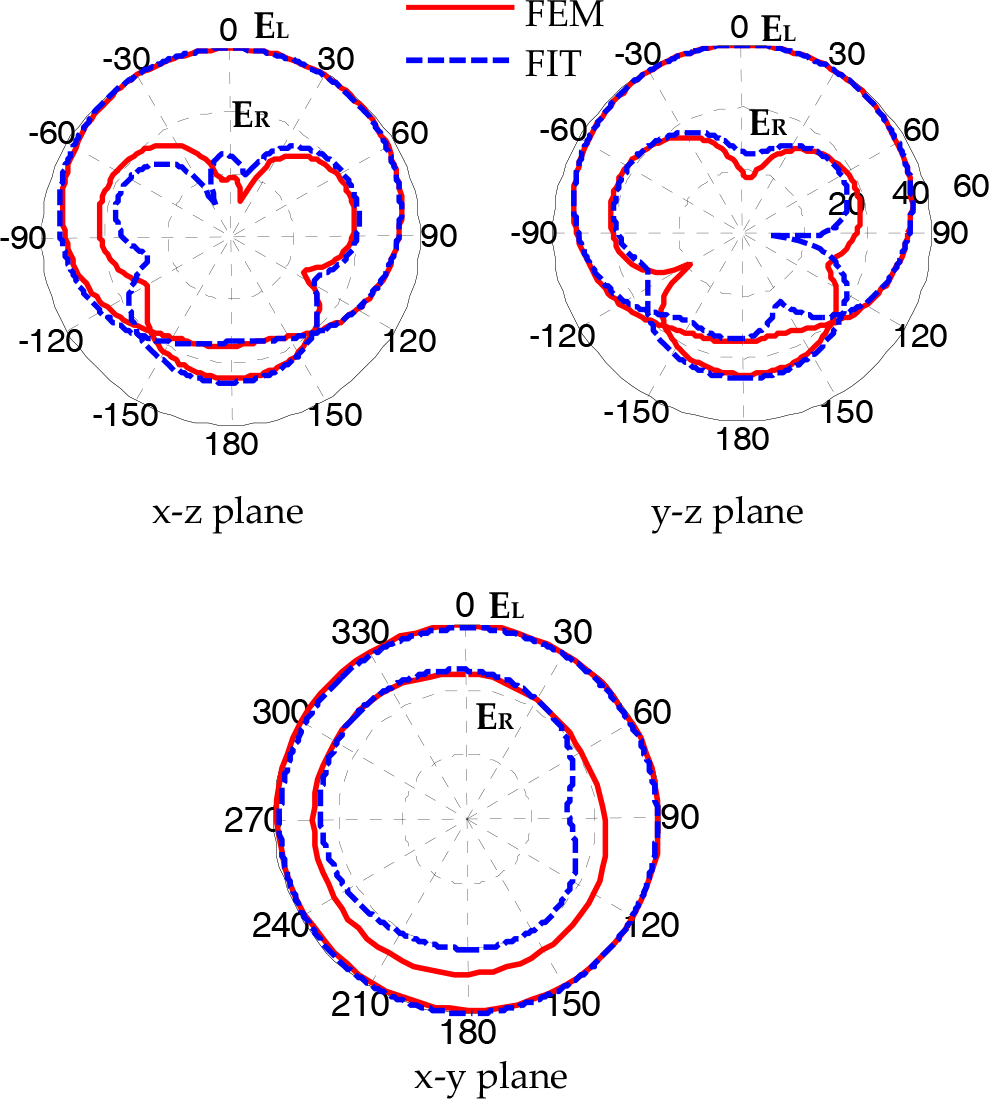
The polarization patterns of the OFHA in the presence of reader device and human hand at f=915 MHz.

A 3-D radiation pattern of the OFHA in the presence of reader device and human hand at f=915 MHz.

The Gain and axial ratio of the OFHA versus observation angle in the presence of reader device and human hand model.
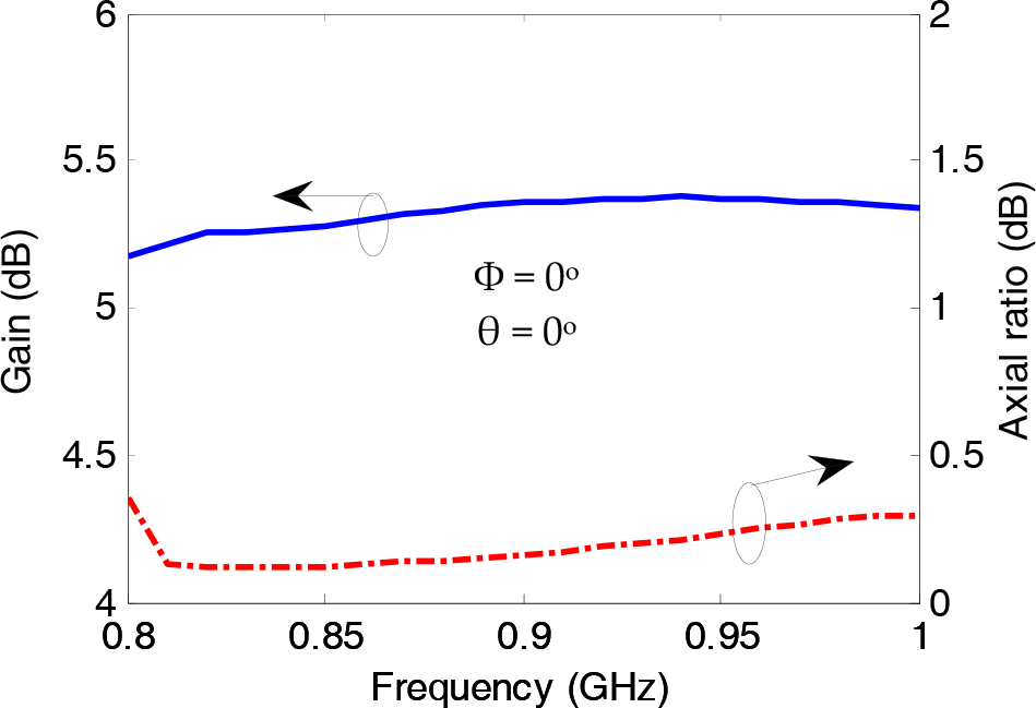
The Gain and axial ratio of the OFHA versus frequency in the presence of reader device and human hand model.
2.3 Comparison Between OFHA and QFHA Placed on a Reader Device in The Presence of Human Hand Model
A comparison using the FEM between the QFHA and proposed OFHA radiation characteristics on the presence of the reader device and human hand model at 915 MHz is presented in Fig. 8.13. The QFHA antenna consists of two bifilar arms in phase quadrateure in orientation and phase shift. The dimensions of the QFHA antenna are optimized for 915 MHz operation. The dimensions of QFHA are Ro = 16.39 mm, H = 95.9 mm, La = 100.9 mm, and Ra = 17.4 mm. The impedance bandwidth of the OFHA is much better than that of the QFHA. The OFHA has high front to back ratio and more omnidirectional pattern than QFHA as shown in Fig. 13.a. The input impedance of the OFHA is lower than that of the QFHA as depicted in [19] as shown in Fig. 13.b. In this case there is no need for using matching network with OFHA. From Fig. 8.13c and Fig. 8.13d, the OFHA introduces improved gain and axial ratio over the UHF frequency band relative to the QFHA.

The polarization patterns of the OFHA and QFHA in the presence of reader device and human hand at f= 915 MHz.
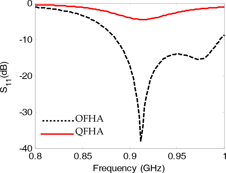
The return loss versus of the OFHA and QFHA in the presence of reader device and human hand.

The Gain of the OFHA and QFHA in the presence of reader device and human hand.

The axial ratio of the OFHA and QFHA in the presence of reader device and human hand.
3. Conclusion
This paper proposes and studies the parameters of an OFHA for handheld UHF RFID reader. The performance of the antenna is investigated using FEM and compared with that calculated by FIT for verifying the results in free space. The OFHA in free space has gain of 5.425 dB and axial ratio of 0.218 dB at f=915 MHz. A simulated model for a handheld reader device in the presence of the human hand is developed. The OFHA is placed on the reader device model in such away that there is little effect on the radiation characteristics of the antenna. The circular polarized field components, return loss, gain and axial ratio of the OFHA are calculated. A comparison between the OFHA and QFHA under the same environmental conditions is investigated. The OFHA introduces high gain, good axial ratio, and high front to back ratio, omnidirectional coverage and good impedance matching compared with the conventional QFHA.