
Abstract
This paper presents a new application of dielectric resonator antenna in radio frequency identification system. A curved dual-band dielectric resonator antenna for RFID applications is proposed. The tag antenna is designed to operate at 2.45 GHz (2.25– 2.55 GHz) and 5.8 GHz (5.65– 5.95 GHz) bands. The radiation characteristics of the tag antenna in free space are investigated. The radar cross sections under different loads are obtained. The effect of curvature on the tag antenna performance is explained. Two examples are considered. In the first example, the tag antenna is mounted on cylindrical bottle filled with the Polyethylene material. The effect of the object properties on the radiation characteristics and the radar cross section is investigated. In the second example, the tag antenna is mounted on spherical bottle filled with the Polyethylene material. The radiation and backscattering characteristics are calculated. The Finite Element Method (FEM) is used for simulation and the Finite Integration Technique (FIT) is used to verify the simulated results.
1. Introduction
RFID systems were introduced as a solution for identification of large volume of objects in a shorter period of time. RFID systems provide an automatic means to identify physical objects without the need for line-of-sight communication [1]–[3]. The main components of a RFID system are tags, readers, and host computer. RFID tags are attached to physical objects as a means to identify them. RFID readers convert the radio waves sent from the tags to get the digital data and send the collected data to the host computer.
The use of RFID systems depends on the frequency bands licensed by governments. They include 135 kHz, 13.56 MHz, 868 MHz (Europe), 915 MHz (U.S.), 2.45 GHz, and 5.8 GHz among others [4]. Most of tag antennas are a design compromise between conflicting requirements. The size, shape, sensitivity of operations in proximity to different materials and cost are all important tradeoffs in the overall design. There is no one right transponder for all applications and therefore, this field of RF design is open for innovative ideas.
RFID systems operating at single carrier frequency can hardly handle the great variety of shapes that occur in products and packaging. A dual- band antenna RFID tag is presented in [5] that allow operation in the 13.56 MHz band as well as in the 868 MHz band. In [6], a triple band printed dipole tag antenna is proposed for RFID. The triple- band printed dipole is designed to operate at 0.92 GHz, 2.45 GHz and 5.8 GHz.
Over the past two and half decades, dielectric resonator antennas (DRAs) in various geometries have been modelled and studied [7, 8]. Since the DRAs have negligible metallic loss, it is highly efficient when operated at millimetre wave frequencies. Conversely, a high- permittivity dielectric resonator can be used as a small and low profile antenna operated at lower microwave frequencies. Recently, DRA mounted on or embedded in metal circular cylindrical, superquadric cylindrical ground plane and spherical ground planes are investigated in [9,9]. The effects of curvature on the antenna performance parameters are explained.
In recent years, a dielectric ring resonator fed by an L-shaped microstrip monopole is reported in [11]. The microstrip monopole can radiate at its resonance frequency also excite a hybrid mode in the annular resonator, thus providing greater bandwidth than ordinary dielectric resonator antenna.
In this paper, dual-band dielectric resonator tag antennas for RFID applications based on the antenna structure proposed in [13] are constructed. A dual-band DRA tag antenna is designed to operate at 2.45 GHz (2.25GHz – 2.55 GHz), and 5.8 GHz (5.65 GHz- 5.95 GHz). Two examples are considered. The first one is the RFID on cylindrical Glass bottle filled with Polyethylene material. The second one is the RFID on spherical Glass bottle filled with Polyethylene material. The finite element method (FEM) is used to optimize and analyze tag antenna performance parameters such as reflection coefficient, radiation pattern, reading range and antenna gain. In order to validate the performance of the tag antenna, the parameters are performed using the finite integration technique (FIT) and compared with the results obtained by FEM.
2. Solution Methods
2.1 FEM Solution
FEM is a numerical method that is used to solve boundary-value problems characterized by partial differential equations and a set of boundary conditions [12]. The geometrical domain of a boundary-value problem is discretized using sub-domain elements, called the finite elements (often triangles or quadrilaterals in 2D and tetrahedral, bricks, or prisms in 3D), and the differential equation is applied to a single element after it is brought to a “weak” integro-differential form. A set of shape functions is used to represent the primary unknown variable in the element domain. A set of linear equations is obtained for each element in the discretized domain. A global matrix system is formed after the assembly of all elements. FEM is one of the most successful frequency domain computational methods for electromagnetic simulations. It combines geometrical adaptability and material generality for modelling arbitrary geometries and materials of any composition. More details about FEM can be found in [13].
2.2 FIT Solution
The finite integration technique is a method for time-dependent electromagnetic problems which was developed in [14]. HT solves Maxwell's equations in integral form with respect to space, but in differential form with respect to time:


In order to solve these equations numerically, a finite calculation domain is defined, enclosing the considered application problem. By creating a suitable mesh system, this domain is split up into grid cells in the x, y, and z directions. The spatial discretization of Maxwell's equations is finally performed on these orthogonal grid systems. The electric and magnetic field components can be put in a matrix form that can be solved by a suitable routine. The FIT formulation is a very general method and therefore can be applied to all frequency ranges. The perfect matched layer (PML) is used to simulate the free space for the radiating structures. More details about FIT can be found in [15].
3. RFID Tag Analysis
Commonly antennas are designed to match to a substantially real load in order to minimize the standing waves along the feeding transmission line. However, for RFID antennas, the load is in close proximity to the antenna and also reactive. Therefore, in order to improve the tag performance the power transferred to the load must be maximized [1]. Let Za=R a +j X a and ZC=RC+jXC are the antenna and chip complex impedances respectively. Maximum power transfer occurs when Z a =ZC*. The power transfer efficiency is the ratio of the actual power transferred to the maximum possible power transferred, which is given by [2]

A power wave reflection coefficient can be defined as
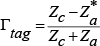
where Z a is the antenna impedance and ZC is the chip impedance. So that τ+|Γtag |2=1. Here, Γtag plays a similar role to Su in the traditional antenna matching problem. The maximum read range of the tag along the (θ, φ) direction, is computed from Friis free-space formula as [6]

where λ is the wavelength, Pt is the power transmitted by the reader, Gt is the gain of the transmitting reader antenna, Gr is the gain of the receiving tag antenna, Pth is the minimum threshold power necessary to provide enough power to the RFID tag chip which is equal to –10 dBm in this case, p is the polarization mismatch factor and τ is power transmission coefficient. The radar cross section, RCS, can be altered by terminating the antenna with different load impedances, where the modulation depth of the RCS affects the tag reading range [16]–[19]. Generally the RCS of a tag antenna can be defined by

where
In the backscattering-modulation process, the tag responds to the reader by varying the impedance of the IC chip from conjugate matching state with (ZC=Z a ) to one of the following states: short circuit (ZC=0), or open circuit (ZC=∞), or changing real part of the IC chip impedance, or changing the imaginary part of the IC chip impedance. By changing the IC chip impedance, the RCS of the tag and the power received by the reader are changed. The difference between radar cross sections from conjugate matching state and any other state is called the differential (or delta) RCS (Δσ) which is to be detected by the reader. An incident plane wave travelling in y-direction is used to excite the tag antenna. The scattered field calculated with this load impedance represents the field seen by the reader. Typically tag antenna responds to the reader by either varying the amplitude of the backscattered fields (ASK modulation) or the phase of the backscattered fields (PSK modulation). In this simulation the modulation is made by varying the real part (for ASK) or the imaginary part (for PSK) of the IC chip load impedance [20]
4. Numerical Results
The geometry of the curved dual-band RFID tag antenna in free space is shown in Fig. 1. The antenna structure is based on the design has been reported in [275]. A dielectric ring resonator with relative permittivity εrd =37 (Ca4.82Mg0.18Ta2TiO12) [21], inner radius R1 =1 mm, outer radius R2 =4.44 mm and height Hd =1 mm, is placed on the FR4-epoxy substrate of relative permittivity εrs =4.4, tanδ=0.02 and has a dimension of Ls×Ws×Hs =26×29×1 mm3 with printed L-shaped microstrip monopole of dimensions Lm1 =16.5 mm, Lm2 =15.5 mm, and width Wm =0.5 mm. The L-shaped monopole has conductor thickness of 0.06 mm. The corner of the L-shaped monopole is at (–7.76 mm, 2 mm). The center of dielectric ring resonator is at (0, –7 mm). A partial ground plane is placed on the substrate back with dimensions Lg×Wg =26×5 mm2. The total length of the L-shape monopole is 2(Lm1+Lm2) which is approximately half wavelength of the first resonance frequency 2.45 GHz. Thus the L-shape monopole is responsible for the presence of the first resonance frequency at 2.45 GHz. The dimensions of the dielectric ring resonator are chosen to be resonating at the second band of 5.8 GHz. However, it is difficult to develop an analytical expression of the resonant frequency, and most analyses of ring resonators up to date are based on numerical methods [13]. Using simulation in HFSS, the dielectric ring resonator has the lowest resonance frequency about 5.85 GHz. Thus the dielectric resonator is at its resonance in the higher band. But in the lower band, the dielectric resonator is below its resonance and works as a high relative permittivity load. Therefore, in the lower band, the monopole is the major radiator, and its resonance frequency is determined by its length.

The geometry of the curved dual-band RFID tag antenna in free space.
The dielectric ring resonator has a planar top surface while its bottom surface will follow the shape of the tag curvature in free space or the shape of the surface of the attached object as discussed previously in chapter six. Similarly, the L-shape monopole, substrate, and the partial ground plane will follow the shape of the tag curvature in free space or the shape of the surface of the attached object. RC is the radius of curvature of the RFID tag antenna in free space, and Φ is the curvature angle of the tag antenna (These symbols will represent the radius and angle of curvature for the tag's attached object). First, the antenna dimensions are optimized in free space for conjugate matching with the Philips RFID/ASIC chip having an input impedance ZC=28-j111.9 Ω at 2.45 GHz and ZC=28-j47.3 Ω at 5.8 GHz at minimum received power of –10 dBm [20]. The IC-microchip is placed between the L-shaped monopole and the partial ground plane as shown in Fig. 1.
The radiation characteristics of the proposed tag antenna including the antenna input impedance, chip impedance, the reflection coefficient, the power transmission coefficient, the antenna gain and the read range as functions of frequency for the planar RFID tag antenna in free space are shown in Fig. 2. The antenna input impedance is conjugate matched with the IC-microchip capacitive impedance at the two resonance frequencies resulting in two impedance matching bands, where the lower band is 140 MHz (2.39– 2.53 GHz) and higher band is 630 MHz (5.49– 6.12 GHz) as shown in Fig. 2a. Good impedance matching is obtained in both the lower and higher bands with –30.5 dB and –35.2 dB reflection coefficient respectively as shown in Fig. 2b. Thus high power transmission is occurred at the two resonance frequencies as depicted from the variation of the power transmission coefficient ratio shown in Fig.2c. The gain variation versus frequency is shown in Fig. 2d. The antenna gain (as a ratio) is 0.25 at 2.45 GHz and 2.5 at 5.8 GHz. Using the read range equation given by eq. (3.3) the RFID tag gives maximum read range of 0.95 m and 1.3 m at the resonance frequency of the two bands respectively as depicted from Fig. 2e. The results of the RFID tag antenna in free space is calculated using FEM and compared with that calculated by using FIT are illustrated. Good agreements are obtained.

The characteristics of the planar dual-band RFID tag antenna in free space.
The simulated radiation patterns in different planes at the lower resonance frequency (f1 =2.45 GHz) and the higher resonance frequency (f2 =5.8 GHz) are plotted in Fig. 3 for the planar RFID tag antenna in free space. An omni-directional radiation pattern is obtained in x-z plane at f1 =2.45 GHz and f2 =5.8 GHz which meets the RFID system requirements.

The radiation patterns of the planar dual-band RFID tag antenna in free space at different planes.
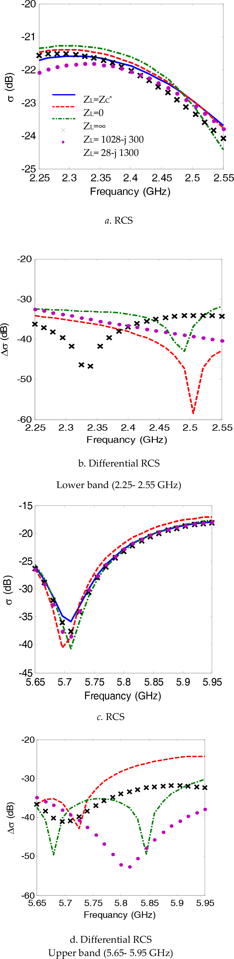
Figure 4a shows the radar cross section for the planar RFID tag antenna in free space against the frequency in the lower frequency band (2.25– 2.55 GHz). The impedance of the IC-microchip changes its load impedance between two different states, matching state and high impedance state as discussed in Chapter three. Different antenna loads are considered. Cases include chip impedance conjugate matching state (ZC =Za*=28–111.9 at f1=2.45 GHz and ZC=Za*=28– j47.3 at f2=5.8 GHz), short circuit state (ZC = 0), open circuit state (ZC = ∞), resistive load state (ZC =1028– j111.9 at f1=2.45 GHz and ZC=1028– j47.3 at f2=5.8 GHz) to produce amplitude variation in the scattered field, and capacitive load state (ZC=28– j1111.9 at f1=2.45 GHz and ZC=28– j1047.3 at f2=5.8 GHz) to give phase variation in the scattered field are considered. Minimum RCS is obtained for the open circuit loading state due to the minimum area of radiation from the antenna while the short circuit loading state provide the maximum RCS from the antenna because of the maximum area of radiation. Figure 4b shows the differential radar cross section (Δσ) between the impedance matching state and one of the other high impedance states for the RFID tag antenna in free space against the frequency in the lower frequency band for different load impedances. Maximum (Δσ) is obtained at the RFID resonance frequency of 2.45 GHz. Figures 4c and 4d show the radar cross section and the differential radar cross section (Δσ) for the planar RFID tag antenna in free space against the frequency in the upper frequency band (5.65– 5.95 GHz) at different antenna loads [242, 243].

The RCS and differential RCS for planar dual-band RFID tag antenna in free space loaded with different load impedances.
4.1 The Effect of Curvature on Dual-Band DRA Tag Antenna in Free Space
Practically the RFID tag is attached to different objects. The shape, size, material and contents of the object affect the performance of the RFID tag. The attached objects may have a planar flat surface or a curved surface [276–279]. The RFID tags operates in the microwave frequency band with center frequencies given as 2.45 GHz and 5.8 GHz. The RFID tag has principal applications in chemical and pharmaceutical industries. Objects may have different surface shapes such as planar, cylindrical, or spherical. The geometry of the curved tag antenna (at different radii of curvature) in free space is shown in Fig. 5. The bottom surface of the DRA is curved following the shape of tag curvature while the top surface is kept planar with the tag dimensions are kept the same as in the perivous section.

The geometry of the tag antenna in free space at different radii of curvature.
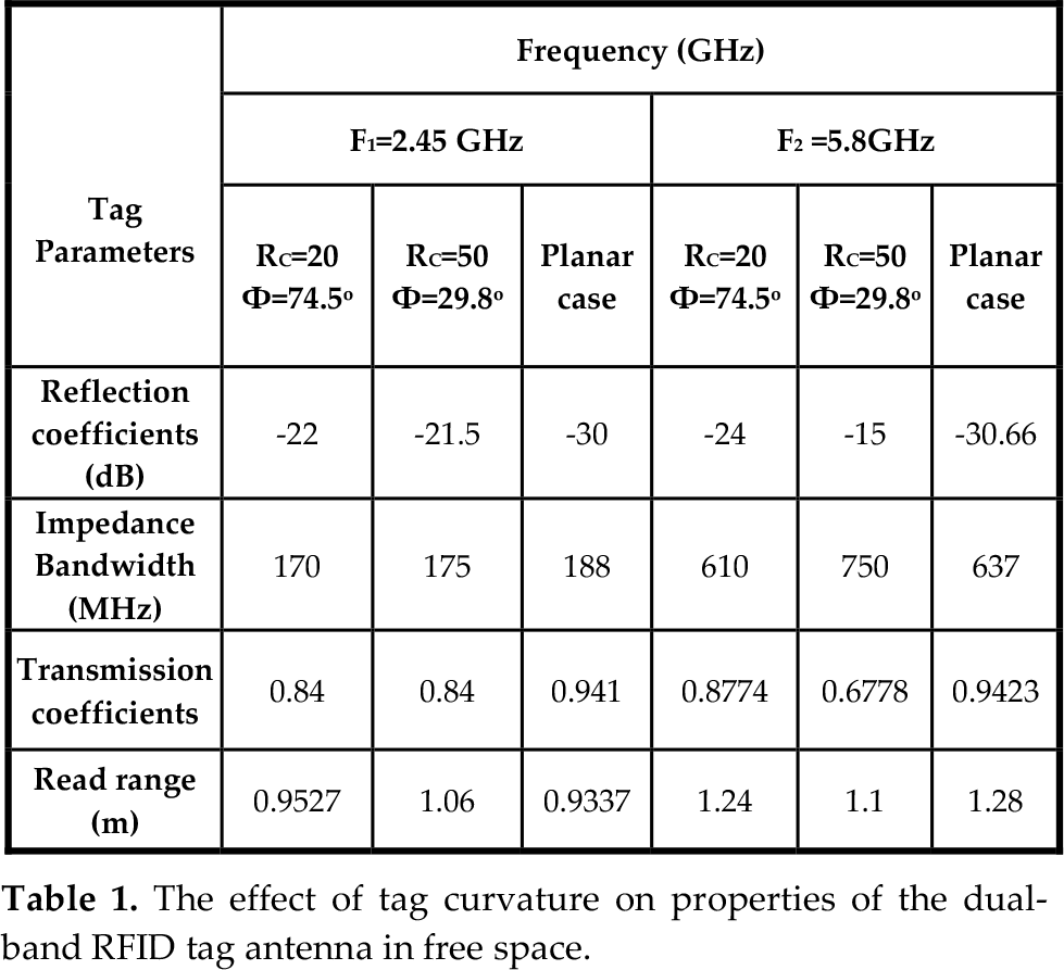
The effect of the tag curvature on its radiation characteristics in free space at different radii of curvature (RC =20 mm, Φ =74.5°), (RC =50 mm, Φ =29.8°) compared with the planar case is depicted in Fig. 6. There is a slit change in the amplitude of the tag antenna input impedance at different radii of curvature. As the radius of curvature is decreased, the height of the DRA (height only at its axis is kept constant) is increased while all the other dimensions are not affected and are the same as the planar case. Thus changing the radius of curvature has only effect on the DRA which reflect itself in changes in the higher frequency band which is responsible for. As the radius of curvature is increased the input impedance of the curved tag approaches that of the planar case as shown in Fig. 6a. Figure 6, shows that changing the radius of curvature have a little effect on the matching conditions and the impedance matching bandwidth of the reflection coefficient, transmission coefficient, gain, and the read range in the lower frequency band. While in the upper frequency band there is a small shift in the resonance frequency to about 70 MHz at RC =20 mm, F =74.5° and 40 MHz at RC =50 mm, Φ =29.8° compared with the similar results in the planar case. As the radius of curvature is decreased the gain and read range of the tag antenna at the upper resonance frequency is decreased while not affected at the lower resonance frequency.

The effect of curvature on the radiation characteristics of the dual-band RFID tag antenna in free space
Table 1. Summarize a comparison between the reflection coefficient, impedance matching bandwidth, the power transmission coefficient and the read range for different radii of curvature. The simulated radiation patterns in different planes at the lower resonance frequency (f1 =2.45 GHz) and upper resonance frequency (f2 =5.8 GHz) at different radii of curvature (RC =20 mm, Φ =74.5°), (RC =50 mm, Φ =29.8°) compared with the planar case are plotted in Fig. 7. Changing the radius of curvature of the dual-band tag has almost no effect on the radiation patterns in different planes compared with the planar case at both the lower and upper resonance frequency. Omnidirectional pattern still observed in the x-z plane at both the lower and upper resonance frequency.
The effect of tag curvature on properties of the dual-band RFID tag antenna in free space.

The effect of curvature on radiation patterns of the dual-band RFID tag antenna in free space in different planes.
4.2. Dual-Band DRA Tag Antenna Mounted on Cylindrical Glass Bottle Filled with Liquid
As depicted from [3] that the RFID tag has high sensitivity of operations in proximity to objects made from materials with different electrical properties containing object of different materials. Thus the RFID tag antenna dimensions are re-designed according to the change of size, shape or materials of the attached object. Figure 8 shows the proposed RFID tag antenna mounted on cylindrical Glass PTFE-reinf bottle with relative permittivity εrb =2.5, tanδ =0.02 with dimensions Hb×Rb×tb =160×40×5 mm3, H2 =20 mm, R2 =12 mm, and H3 =20 mm. The cylindrical bottle is filled with Palmitic Acid material (Liquid) of εrp = 2.25, tanδ=0.001 and height H1 =120 mm, R1 =30 mm. The bottle top is closed by rubber hard sphere with εr =3 and radius R3 = 10 mm connected with cylinder of dimensions R4×H4 =7 ×15 mm2, and H5 =17.15 mm. The bottle may be filled with any other liquid material with different properties as will be discussed later.

The curved dual-band RFID tag antenna configuration mounted on cylindrical Glass bottle filled with the Polyethylene material (RC=40 mm, Φ=37.4°).
The performance of the RFID tag antenna when mounted on the cylindrical glass bottle filled with liquid material is changed compared with the free space case. Thus a re-design of the antenna dimensions is performed in order to tuning the antenna input impedance for conjugate matching with the IC-microchip. The re-designed RFID tag antenna parameters are Lm1 =18 mm, Lm2 =12 mm, Hd =0.5 mm, Hs =0.6 mm, and The center of ring resonator is at (0, − 2.5 mm). The corner of the L-shaped monopole is at (–6.07 mm, 5.5 mm), while keeping all other parameters fixed as in Fig. 1. Figure 9 shows the performance parameters of the re-designed tag antenna when mounted on a cylindrical Glass bottle filled with Palmitic-Acid material. Good agreements between the present method and FIT method are obtained. The re-designed antenna input impedance is conjugate matched with the IC-microchip capacitive impedance of –25 dB and –40.6 dB at the lower and upper frequency resonance frequencies respectively. The impedance matching bandwidth is 160 MHz (2.4–2.56 GHz) in the lower frequency band while 690 MHz (5.47– 6.16 GHz) in the upper frequency band. The antenna gain (ratio) is increased compared with the planar tag in free space resulting in 4.16 at 2.45 GHz and 3.74 at 5.8 GHz. The attenuation in the liquid is increased with increasing the operating frequency resulting in degradation in the antenna gain at the upper resonance frequency. Thus the RFID tag read range has a maximum value of 3 m and 2.35 m at the lower and upper frequencies respectively.

The radiation characteristics of the curved dual-band RFID tag antenna mounted on cylindrical Glass bottle filled with Palmitic-Acid (RC=40 mm, Φ=37.4°).
The simulated radiation patterns in different planes at the lower resonance frequency (f1 =2.45 GHz) are plotted in Fig. 10a, while the patterns at the higher resonance frequency (f2 =5.8 GHz) are plotted in Fig. 10b for the RFID tag antenna mounted on cylindrical Glass bottle. Nearly omnidirectional patterns are obtained in different planes. The radar cross section and the differential RCS of the RFID tag antenna mounted on cylindrical bottle at different load impedances are demonstrated in Fig. 11. The presence of the object changes the shape and the values of the radar cross section at different load impedances due to the effect of the dielectric properties of the cylindrical glass bottle. The presence of the liquid inside the bottle increases the RCS from the antenna compared with the free space case.

The radiation patterns in different planes for the curved dual-band RFID tag antenna mounted on cylindrical Glass bottle filled with Polyethylene (RC=40 mm, Φ=37.4°).
The RCS and differential RCS for curved dual-band RFID tag antenna mounted on cylindrical Glass bottle filled with Polyethylene material at different load impedances.
4.3 Dual-Band DRA Tag Antenna Mounted on Cylindrical Glass Bottle Filled with Water and Water-Like Liquids
The DRA tag antenna behavior near water or water like liquids is investigated. The tag antenna dimensions are tuned to give the same resonance frequencies (f1=2.45 GHz and f2=5.8 GHz). The center of the ring DRA is moved to (0,-0.5mm) while all other dimensions are kept as in Fig.8. Figure 12, shows a comparison between the behavior of the tuned tag antenna when the cylindrical Glass bottle is empty, filled with distilled water of μr=78.4, σ=0.99, 0=5.55×10⁻⁶ s/m, and water like material with εr=55.6. The water contained in the cylindrical Glass bottle degrades the performance of the whole tag antenna and reduces the antenna gain and the read range. This effect is due to the discontinuity in the dielectric constant between the object material and its content material. The absorption of power dissolves the water material leading to high power attenuation and thus the antenna gain is reduced. This reduction in antenna gain reduces the maximum read range of the tag.

The radiation characteristics of the curved dual-band RFID tag antenna mounted on cylindrical Glass bottle with (RC=40 mm, Φ=37.4°) filled with water distilled (εr=78.4, μr=0.99, σ=5.55×10⁻⁶ s/m), water like (εr=55.6) and empty case.
4.4 Dual-Band DRA Tag Antenna Mounted on Spherical Glass Bottle Filled Liquid Material
The effect of the shape and size of the attached object on the radiation characteristics of the RFID tag is investigated. Keeping the material contained in the bottle the same as that in section 4.2 and changing the shape and size of the bottle to spherical shape with the same material properties as presented in Fig. 13. The tag antenna is mounted on a spherical Glass PTFE-reinf bottle with relative permittivity εrb = 2.5, tanδ =0.02 with dimensions Hb×Rb×tb =137.5×50×5 mm3, H2 =15 mm, R2 =15 mm, and H3 =15 mm, R3 =7.5 mm. The spherical bottle is filled with Palmitic Acid material of εrp = 2.25, tanδ =0.001, height H1 =65 mm, and R1 =27.5 mm. The bottle top is closed by rubber hard sphere with εr =3 and radius R3 =7.5 mm connected with cylinder of dimensions R4×H4 =4 ×15 mm2. The RFID tag antenna dimensions are the same as in Fig. 8.

The curved dual-band RFID tag antenna configuration mounted on spherical Glass bottle filled with the Polyethylene (RC=50 mm, Φ=29.8°).
The different performance parameters of the RFID tag mounted on spherical bottle filled with Palmitic acid are presented in Fig. 14. Almost good agreements between results calculated by the FEM and that calculated by FIT method are obtained. Changing the shape and size of the attached object has almost little effect on the performance of the RFID tag. The tag antenna is conjugate matched to the IC-microchip with refection coefficient of –21 dB at the lower resonance frequency while –61 dB at the upper resonance frequency. The impedance matching bandwidth is about 160 MHz (2.4–2.56 GHz) and 1200 MHz (5.1–6.3 GHz) at the lower and upper bands respectively. As depicted from section 4.1 changing the size of the attached object has almost no effect on the bandwidth of the lower band while it has increasing the impedance matching bandwidth of the upper band. The antenna gain is increased resulting in an increase in the tag read range of 3.37 m and 3 m at the lower and upper resonance frequency respectively. The simulated radiation patterns in different planes at f1 =2.45 GHz for the tag antenna mounted on a spherical bottle are illustrated in Fig. 15. Omni-directional patterns still preserved.

The radiation characteristics of the curved dual-band RFID tag antenna mounted on spherical Glass bottle filled with Palmitic Acid material (RC=40 mm, Φ=29.8°).

The radiation pattern in different planes for the curved dual-band RFID tag antenna mounted on spherical Glass bottle (RC=40 mm, Φ=29.8°).
5. Conclusions
A design of dual-band dielectric resonator antenna for RFID tag applications on 2.45 GHz (2.25–2.55 GHz) and 5.8 GHz (5.65–5.95 GHz) frequency bands has been proposed. The antenna has good impedance matching with commercially available IC-microchip without using additional matching network. The curvature has little effect on the antenna input impedance, reflection coefficient, transmission coefficient and the read range in the lower frequency band. While in the upper frequency band there is a small shift in the resonance frequency to about 70 MHz at RC =20 mm, Φ =74.5° and 40 MHz at RC =50 mm, Φ =29.8°. The effect of attaching the tag to bottles with different shapes (cylindrical or spherical) made from different material properties and containing liquids with different material properties is calculated. A re-design for the RFID tag dimensions is needed when it attached to object with different material properties in order to retrieve the proper performance of the tag (matching conditions). The electrical properties of the material includes in the attached object degrades the performance of the RFID tag compared with that of free space or empty bottle case. Changing the size of the attached object with the same material properties and material contents have almost no effect on the resonance frequency of the lower band while has a great effect on the resonance frequency of the upper band. The shape of the attached object broadens the upper impedance matching bandwidth while no affecting the lower band. The performance degradation in the lower band can be tuned through the L-shape monopole while in the upper band is through the dielectric ring resonator.