
Abstract
The design of a NF- focused DRA phased array antenna is implemented for fixed RFID reader applications at 5.8 GHz. The radiated field is focused in the near-zone of the array aperture. Numerical investigations on the radiation characteristics of the NF- focused array as well as uniform phase array are presented to demonstrate its feasibility for RFID real applications.
1. Introduction
Radio Frequency Identification (RFID) constitutes revolutionizing methods of identification and traceability that are among the major concerns of industry. RFID systems are utilized in many different applications such as in real-time identification, asset tracking, intelligent transportation, security surveillance and management processes [1]–[2]. Practically, RFID reader has a read zone that can sometimes be difficult to control due to multi-path effects or reflections of the RF signal. Problems that may arise with conventional RFID readers include:1) the reader may detect tags that are not in the reader coverage area, and 2) the tags may be located adjacent to the reader antenna thus blocking its field. The RFID reader antenna is an important component in RFID systems and has been designed with circularly polarized (CP) operation. CP antennas can reduce the loss caused by the multi-path effects between the reader and the tag antenna. A CP antenna with a low profile, small size, lightweight, high gain, and high front-to-back ratio is required in a portable RFID reader [3]–[5]. Recently, fixed-reader antennas are becoming more complex patch arrays with high gain, narrow beam and low side lobe level [6]–[7]. However, for some applications, tags may be located in the near-field region of the reader antenna not in its far-field region. Therefore, a reader antenna array exhibiting a near-field (NF) focused radiation, which is able to maximize the field amplitude in a size-limited spot within the antenna near-field region, while not affecting the field strength far from the antenna (far-field region) is needed.
Recently, NF-focusing has attracted major interest due to its potential applications in near-field sensing and imaging microscopy [8]–[10]. NF- Focusing is used in RFID to increase the field incident on the tags at allowed effective isotropic radiated power (EIRP) kept constant [11]. Dielectric resonator antennas (DRAs) have attracted broad attention in many applications due to their many attractive features in terms of high radiation efficiency, wide bandwidth, light weight, small size and low profile [12]. Perforated structure was applied in [13, 14] to overcome the mounting problems of the DR over the ground plane. In this paper, an 8×8 NF-focused DRA phased array with supporting arms for fixed RFID reader at 5.8 GHz is proposed. The NF-focused DRA array is designed to maximize the radiated power density in a limited size spot area in the near field of the reader. The performance parameters of the NF-focused array are compared with that of uniform phased array. The finite integration technique (FIT) [15] is used to optimize and analyze the antenna array performance parameters such as reflection coefficient, radiation pattern and antenna gain. The finite element method (FEM) is used to validate the results [16].
The paper is organized as follows. In Section II, numerical results for a circularly polarized DRA with supporting arms as a building block for the RFID reader antenna array are investigated. Near field focused DRA array for fixed RFID reader consists of 4×4 sub-array (64 DRA elements) is designed at 5.8 GHz. Section III concludes the results.
2. Numerical Results
2.1 Single Element
A circularly polarized elliptical dielectric resonator antenna (EDRA) with supporting arms using a single feeding probe resonating at 5.8 GHz is shown in Fig. 1. A detailed study for designing a circularly polarized superqudric dielectric resonator antenna using a single feed has been carried out in [17]. According to that study, a circularly polarized DRA with elliptical cross-section using a single feed has been designed and optimized for portable RFID reader antenna. The antenna cross section is chosen to be elliptical, with major axis radius ‘b’ of 8.4 mm, minor axis radius ‘a’ of 5.6 mm, and the height ‘Hd’ of 5.8 mm with dielectric constant ‘εr’ of 12. A coaxial probe, with radius 0.25 mm and height ‘hf’ of 4.8 mm, is used to excite the DRA. The probe location is optimized to be off-center at (Wx, Wy) of (3.2 mm, –3.2 mm) for circular polarization. The elliptical DRA is mounted on square ground plane with edge length ‘G’ of 35.15 mm. The supporting arms have rectangular shape with width Wp= 4 mm, and thickness Hp=1 mm. The supporting arms are perforated by incorporating air holes in the arms. The air holes have equal radii, Rp=1.1 mm and center to center separation Sp=3Rp. Perforated structure was proposed in [13] to overcome the mounting problems of the DR over the ground plane and more manual effort in the alignment of the DRA with the feeding structure especially for arrays.

The geometry of the single element circularly polarized elliptical DRA with supporting arms.
Later, the perforated technique was used in the dielectric Fresnel lens design to obtain proper phase compensation and gain enhancement [14]. The technique of perforating a dielectric sheet eliminates the need to position and bond individual DRA elements in an array. Perforations create different effective dielectric permittivity and make the fabrication of DRA arrays feasible. The perforations result in lowering the effective dielectric constant for the region between the DRA elements. The EDRA element is made from one piece of material; with a perforated bonding dielectric rods and completely eliminating all the rest of the dielectric materials. The dielectric rods have low dielectric constant and thin enough to avoid guiding waves around the design frequency of the element itself.
The effective dielectric constant, εreff, of the perforated material can be calculated from [14]


where Rp is the radius of the air holes, and Sp is the center to center separation distance of the holes. Thus, the supporting arms are used to reduce the fabrication complexity while keeping the same radiation characteristic as the case for the absence of the supporting arms (free element) [14].
Figure 2a shows the simulated return loss, S11, of the single element with perforated supporting arms against the frequency. The impedance bandwidth is extended from 5.44 GHz to 6.15 GHz for S11 < –10 dB. The simulated results by FIT show good agreements with those calculated by FEM. The variations of the input impedance against the frequency are presented in Fig. 2b. The antenna provides good impedance matching with a 50 Ω coaxial cable over the band (5.65– 5.95 GHz).

The return loss and the input impedance versus frequency for the single DRA element.
The simulated radiation pattern components, left hand polarization, EL, and right hand polarization, ER, of the single element at 5.8 GHz in x-z plane and y-z plane are shown in Fig. 3. Asymmetrical radiation patterns are obtained in both the x-z plane and y-z plane due to the asymmetrical position of the feeding probe. The half-power beam width (HPBW) is 86° and 82° in the x-z plane and y-z plane respectively. The axial ratio at the normal axis, φ= θ=0, versus frequency is shown in Fig. 4a. The antenna provides circular polarization bandwidth of 0.15 GHz for AR<3 dB (from 5.7 GHz to 5.85 GHz) and with minimum value of 1.85 dB at 5.8 GHz. The antenna gain at the normal axis over the operating band is shown in Fig. 4b. The maximum gain at the normal axis is 6.67 dB at 5.8 GHz and nearly constant within 0.5 dB over the RFID frequency band (5.65– 5.95 GHz).

The radiation characteristics of the single element DRA in different planes at f=5.8 GHz.

The axial ratio and antenna gain of the single element DRA.
2.2 Pair-Unit Array Element
Although a simple probe excitation is used for circular polarization, this method has the disadvantage of providing a narrow bandwidth. On the other hand, an EDRA pair-unit composed of a two elements is well known to have an extremely broad bandwidth [18].
Figure 5 illustrates the arrangement of the EDRA in pair-unit geometry. Each element of this pair- unit is fed uniformly in power from orthogonal feed points F1 and F2, and they are out of phase by –90° from each other with –90° rotation angle of the elements. The distance G between the centers of the elements is 35.172 mm which is about 0.68Λ***o at resonance, i.e. 5.8 GHz. This is to allow for narrowing the main lobe in the composite array pattern. Also, the rotation of the orientation by 90° has been done to achieve orthognality of the fields in the two elements. This ortogonality of the fields directions as well as with the 90° phase shift between the fields will end up producing a circularly polarized radiation.
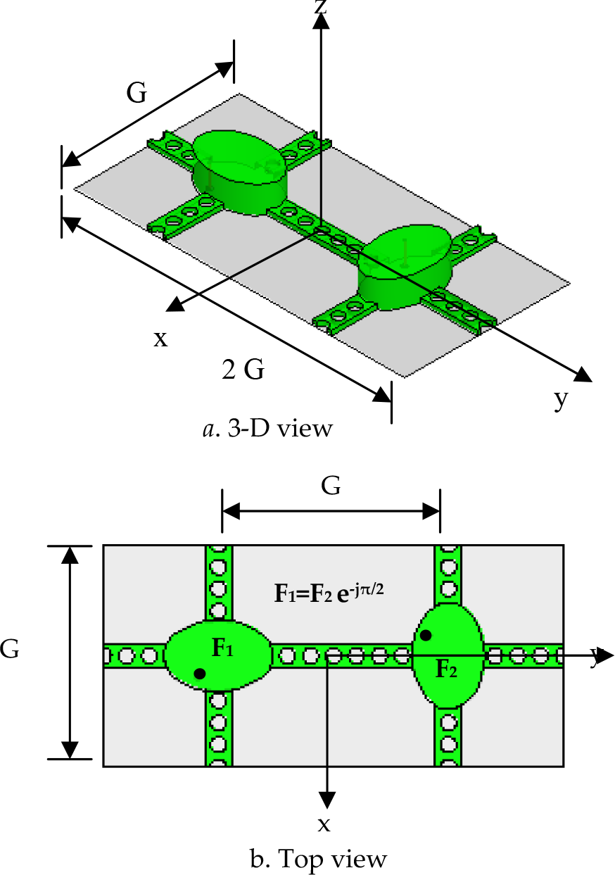
The circularly polarized elliptical EDRA pair- unit array.
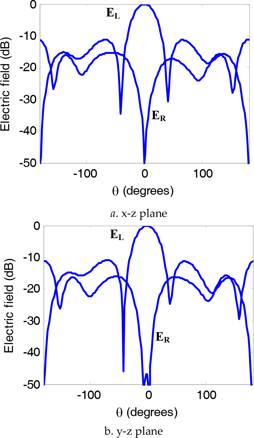
To achieve the condition of matching; the S11, S22, and Zin are computed for the pair- unit and plotted in Fig. 6. Matching is found to be acceptable for the elements from 5.44 GHz to 6.15 GHz. The radiation patterns are computed in plane φ=0, and plane φ=90° as in Fig. 7. A narrow main beam is achieved in the y-z plane with low side lobe level, while asymmetric radiated field is obtained in the x-z plane due to the asymmetrical position of the feeding probes. The HPBW is 82° in the x-z plane and 32° y-z plane respectively.

The characteristics of the pair- unit EDRA with a single feed and supporting arms.

The radiation characteristics of the pair- units elliptical EDRA with a single feed and supporting arms in different planes.
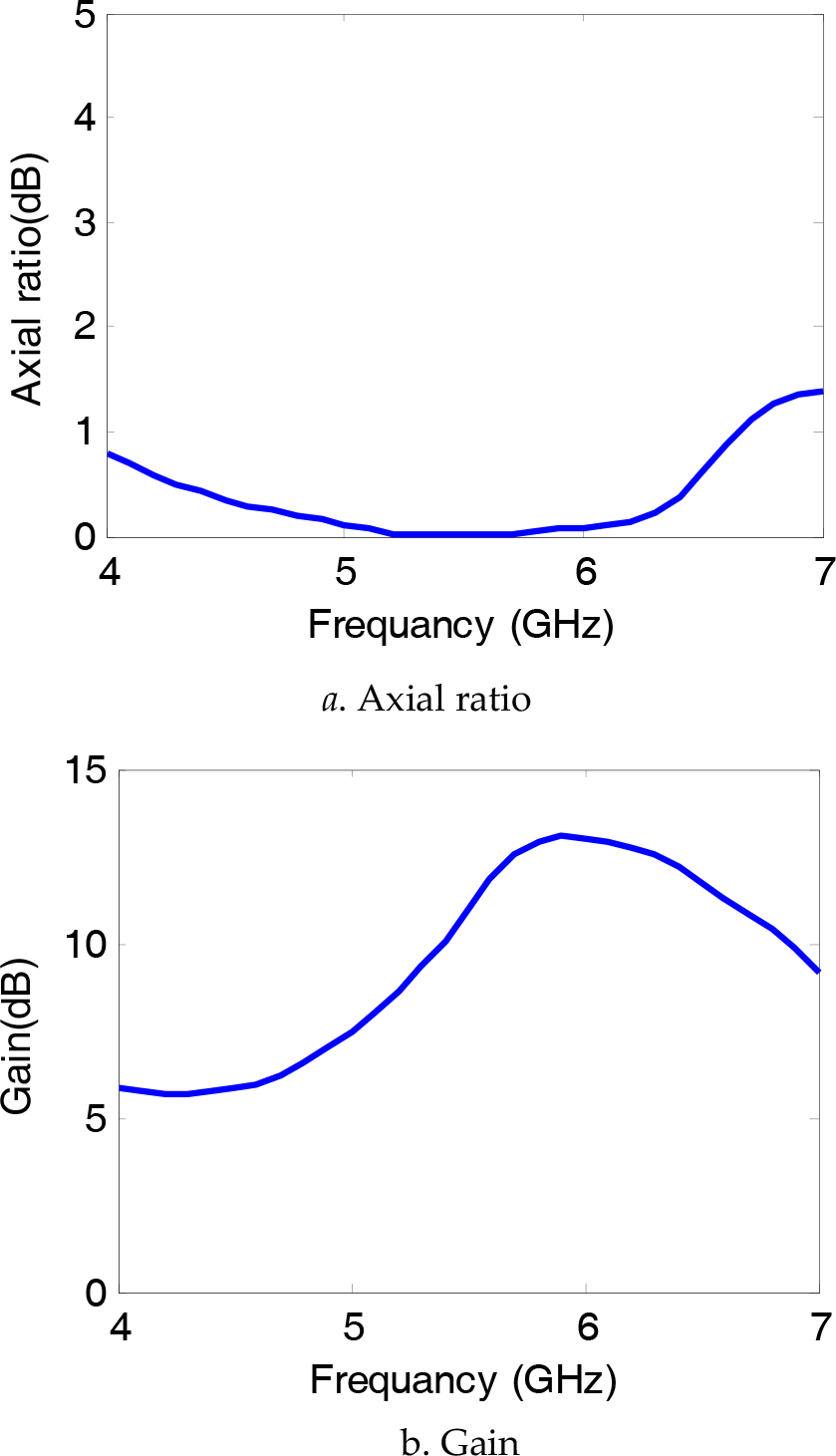
The axial ratio versus frequency for the pair- unit at φ= θ=0 is shown in Fig. 8a. This configuration shows improved bandwidth of 2.45 GHz for AR< 3 dB compared with 0.15 GHz for the single element. The AR is 0.76 dB at frequency f=5.8 GHz. The antenna gain variation over the frequency band at φ= θ=0 for the pair-unit is shown in Fig. 8b. The pair-unit improves the antenna gain to reach 9.69 dB at frequency f=5.8 GHz

The axial ratio and the antenna gain of the pair- unite elliptical EDRA with a single feed and supporting arms.
2.3 2×2 Dielectric Resonator Antenna Elements in a sub-array
The geometry of such four elements in such 2×2 sub-array is used to improve the gain of the reader antenna. The arrangement of the 2×2 EDRA elements in a sub-array is shown in Fig. 9. The phase shift and the orientation rotation have been done to get circular polarization as explained before. The technique of sequentially feeding pairs of single-fed EDRA elements was used to improve the circular polarization bandwidth of the pair-unit [18, 19].
Each element is fed uniformly in power from orthogonal feed points F1 and F2. The elements in one diagonal are 90° out of phase and also rotated 90° in orientation relative to the elements in the other diagonal as shown in Fig. 10. The distance between the geometrical centers of the elements is G to reduce the mutual coupling between the array elements. The return losses, S11, S22, S33, S44 and the input impedance for the sub-array are illustrated in Fig. 11 respectively. The impedance matching bandwidth still preserved from 5.4 GHz to 6.22 GHz for all the array elements.

The geometry of 2×2 DRA elements (sub-array).

The return loss and the input impedance for 2×2 DRA elements (sub-array).
The circular polarization radiation pattern components EL and ER are shown in Fig. 12. Narrow beam width with HPBW of 34° is obtained in both the x-z and y-z planes. The axial ratio versus frequency is shown in Fig. 13a. The sub-array provides an extremely broadband axial ratio bandwidth due to the orthogonality of the array elements in phase and orientation. The sub-array gain versus frequency is presented in Fig.13b providing high gain of 13.1 dB at 5.8 GHz.
The radiation characteristics of 2×2 DRA elements (sub-array) in different planes.
The axial ratio and the antenna gain of 2×2 DRA elements (sub-array).
2.4 8×8 Dielectric Resonator Antenna Elements (4×4 Sub-arrays)
The RFID reader antenna array is shown in Fig. 14. The array is arranged as an 8×8 DRA element which is actually consisting of 4×4 of sub-array elements with each sub-array organized using four DRA elements as explained in section 2.3. The total dimensions of the array are L×L= 28.13 × 28.13 cm2 (5.44 λo***×5.44 λo where λo is the free-space wavelength at 5.8 GHz). The distance between the EDRAs is kept at 0.68 λo when the frequency is 5.8 GHz as mentioned before in order to reduce the mutual coupling between elements. The antenna aperture is in the (x, y) plane and (xi, yi) are the coordinates of the ith element. The phase of the feeding currents has been adjusted to maximize the radiated field at a distance Ro=40 cm (7.73λo) from the antenna aperture. For the NF-focused phased array, the phase shift for the ith element can be calculated from [11]

The geometry of 8×8 DRA array (4×4 sub-arrays)

When the phase is adjusted as in eq. (9.2), the properties of the electric field at the focal plane is exactly the same as those in the far field (for the unfocused case). This was proved theoretically in earlier studies [11].
The beamwidth between 3-dB points in the focal plane is defined as the array spot size. The spot size area radius, W of a NF-focused planar array depends on the inter-element distance, array size and geometry, required focal length and phase profile at the antenna aperture [19]–[20]

For L=28.13 cm, Ro=40 cm, and λo=5.17 cm, W=1.26 λo (which is W= 6.52 cm). The Poynting vector which equals to the cross product of electric field, Ē, by the complex conjugate of the magnetic field, Ĥ. The magnitude of its real part is the active power density while the magnitude of its imaginary part is the reactive power density [21]. Adding the phase shift to the array elements results in focusing both the active and reactive power density at the focal plane (the plane which include the focus point). The ratio between the active power density and the reactive power density is very large (about 127). Thus, only the active radiated power density will be taken into account and given by

The equivalent plane wave power densities are defined from the E-field and H-field as follows

where Se and Sh are the equivalent plane wave power density derived from the E-field and H-field respectively and η o =377Ω. The active power density in the near field given by (Eq. 9.5) compared to the one obtained by equivalent plane wave power density derived from the E-field and H-field given by eq. (9.6) have been presented in [21]. The E-field power density is sufficient for near field (Fresnel region) calculations of the radiated power density. The performance of the 8×8 NF focused DRA array is presented compared to the near-field characteristics of the uniformly phased array.
A 3D view of the normalized power density in the transverse plane (x-y plane) at a distance Ro=40 cm is shown in Fig. 15.

Simulated normalized power density in an 80×80 cm2 area at Ro= 40 cm from the antenna aperture.
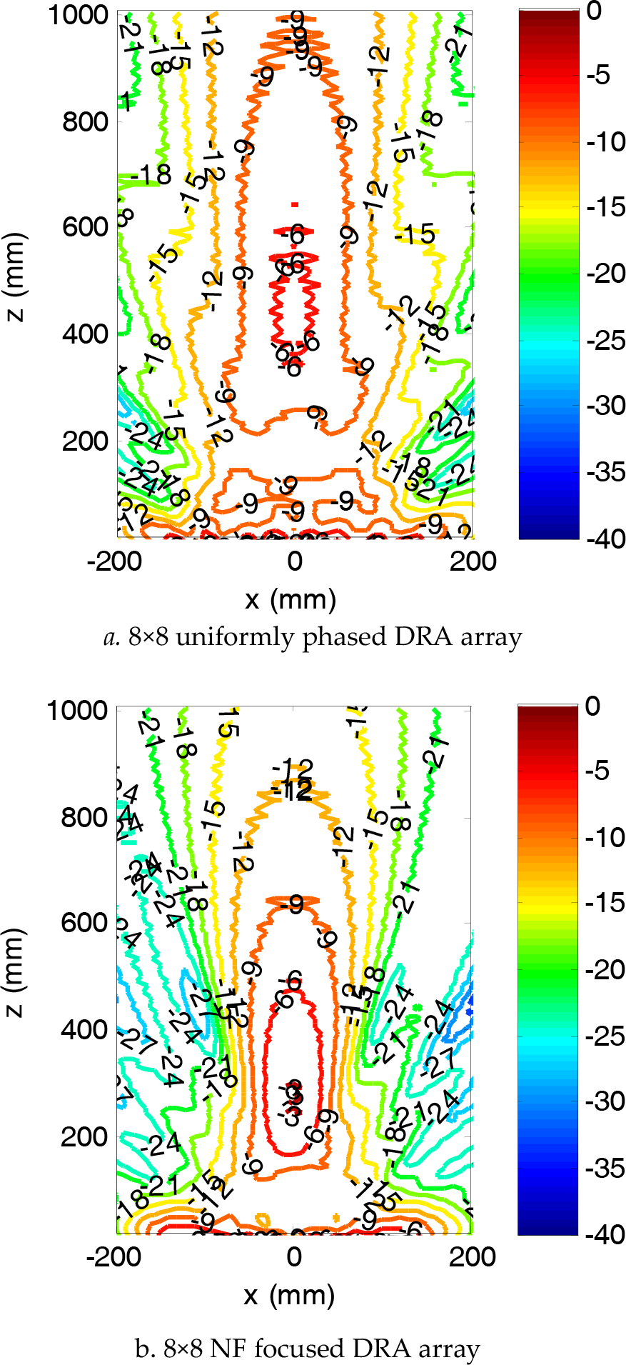
The contour plot of the normalized power density is shown in Figs.16 for uniformly phased EDRA array and the NF-focused EDRA array. The contour curves show that the field amplitude of the power density decays more slowly in the case of uniformly phased array than that for the NF-focused array.

Contour plot of the simulated normalized power density in an 80 ×80 cm2 area at Ro= 40 cm from the antenna aperture.
Figure 17 and Figure 18 shows the contour plot of the normalized power density in the planes orthogonal to the antenna aperture in the y-z plane and x-z plane respectively, for both the NF- focused array case and uniformly phased array case. Figure 19 shows the power density variation along the z-axis at x=y=0 for the NF-focused array. The 3-dB contour curve of the NF-focused array exhibits a diameter of about 30.7 cm. The AR in 40 × 40 cm2 area of the transverse plane at focal point 40 cm away from the NF array aperture is shown in Fig. 20. The NF-focused array exhibits focused circular polarization in area around the focal point less than that for the uniformly phased array.

Contour plot of the simulated normalized power density in an 80 ×1000 cm2 area at Ro= 40 cm on the y-z plane.
Contour plot of the simulated normalized power density in an 80 ×1000 cm2 area at Ro= 40 cm on the x-z plane.
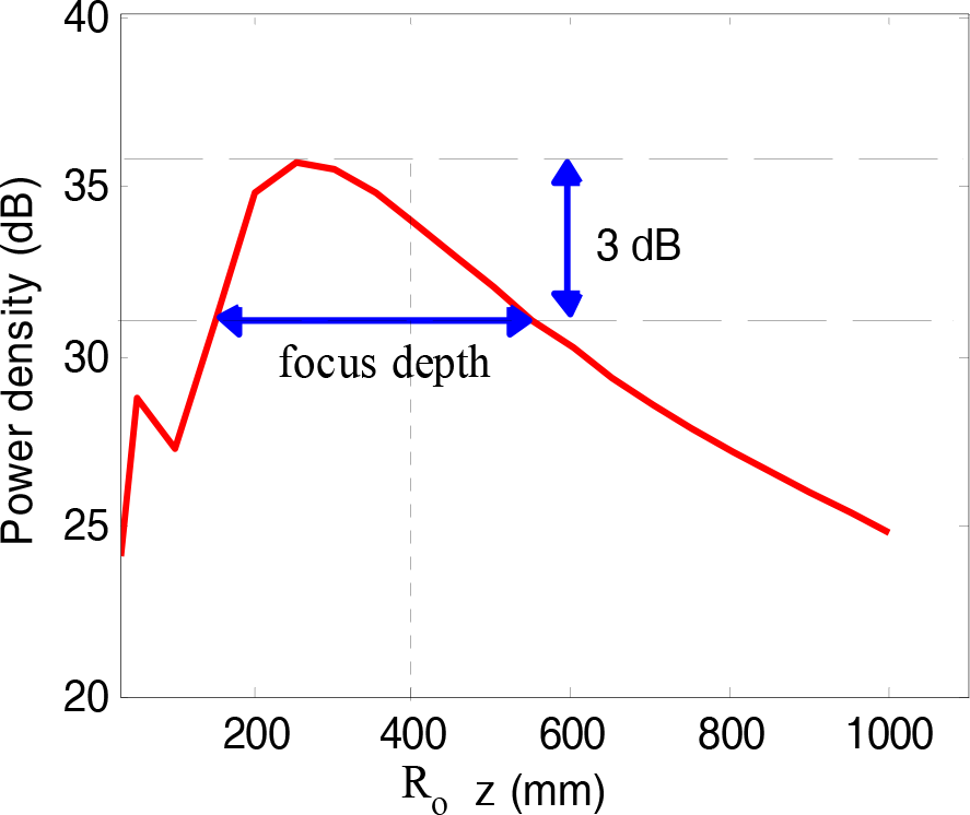
Simulated radiated power density along the axial direction for the NF-focused DRA array.

Contour plot of the simulated axial ratio in an 80 ×80 cm2 area at Ro= 40 cm from the antenna aperture.

Simulated normalized power density along the transverse direction at Ro= 40 cm from the antenna aperture.
The variations of the normalized power density along x- axis and y- axis are shown in Fig. 20 The side lobe level, SLL, in 80 × 80 cm2 area is less than –18 dB while –6.5 dB for the uniformly phased array. The far-field components for 8×8 uniformly phased array in different planes is shown in Fig. 21. Approximately the same field distributions in the far- field region for the uniformly phased array are obtained in the near field region for the NF-focused array (see Fig. 20) due to the phase correction of each element in the array.
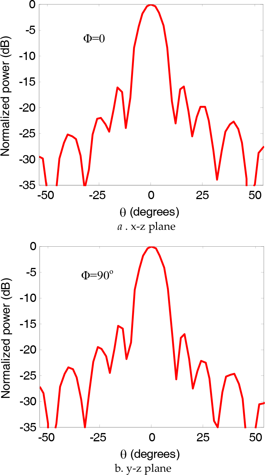
The far- field power pattern of the uniform phase DRA array in different planes.
3. Conclusions
This paper presented the design procedure of an 8×8 NF- focused DRA phased array for fixed RFID reader applications. The array was designed, optimized and analyzed using FIT and FEM. The performance parameters of a circularly polarized DRA with supporting arm as a building block for the RFID reader antenna is investigated. The parameters of the NF- focused array and its uniformly phased version are introduced. Numerical results confirm the feasibility of the proposed phased array configuration as a near field focusing antenna. The NF-focused array introduces a focused spot area with diameter of 13.7 cm and SLL of –16 dB so representing a valuable solution in realistic applications.