
Abstract
In this study, we analyse the work of bipedal walking robots with compliant feet. For this purpose, a walking model of bipedal robots with compliant feet is considered. The ligamentous structure of the human foot is used for the compliant feet mechanisms of the bipedal robot considered herein. A work principle is used for determining the corresponding work at the joint space of the compliant legs according to the reaction force which is propagated from the foot space. The usefulness of the work analysis is demonstrated through exemplary simulations. Consequently, it is shown that the work analysis can be used for evaluating the fatigue of the bipedal robot accumulated by the physical walking impact between the supporting foot and the contact surface. Furthermore, comfortable walking by means of footgear with a compliance is addressed.
Introduction
There has been a significant advance in the research of walking robots mimicking the variety of human functions [1–5]. However, developing a human-friendly robot that is an active or assistant worker in both industrial and social spaces is still a challenging area of research. Recently, an impressive humanoid robot that is available to walk well like a human has been developed [5]. It is actually expected that such an intelligent robot can perform many dangerous tasks as well as various human-friendly tasks on behalf of a person. Even though many studies on the effective walk of bipedal robots exists [6–8], they have not addressed an analysis of compliant legs in terms of comfortable walking. In this paper, we investigate the field of compliant walking which is very important to moderate the shock loads of such bipedal leg mechanisms [9][10].
From the biomimetic point of view, it is valuable to look at the walking behaviours of humans in order to achieve a comfortable robotic walking [11]. If we walk for a long time, we usually experience the joints of each leg getting tired gradually and our body eventually becomes fatigued. This fatigue is basically dependent on the momentum of walking over the length of time. Practically, the shock of each leg by repetitive ground contact may inflict an excessive force on the joints. On the other hand, such an influence of shock might be reduced by employing a certain compliant mechanism. In this sense, we need to check the joint torque effect from the reaction force which is transferred from the foot space during walking. It is also valuable to consider any compliance model of a foot mechanism for compliant robotic walking. Related to compliant walking, rehabilitation and medical researchers have been actively studying in the field of ankle-foot prosthesis for amputees [10]. They have developed a powered foot mechanism with elasticity and addressed the importance of the compliance of the foot mechanism to protect from damage due to foot collision. It is natural that such an elastic foot mechanism is usually helpful for alleviating the shock loads of the ankle. Recently, the joint torque effect resulting from the compliance of a foot mechanism has been discussed [12]. This is meaningful for an effective leg-foot mechanism from the design perspective [13–15]. In addition, a work analysis of each leg is necessary to deal with the issue of comfortable walking for bipedal robotic applications. However, it actually requires significant effort to evaluate the comfortability of walking which is closely related to obtaining good performance of legged robots [16–18].
The objective of this paper is to analyse the work at the joint space of compliant legs for bipedal walking robots. It is finally shown that the work analysis is useful for evaluating the fatigue of the bipedal legs accumulated by the impact of physical walking between the supporting foot and the contact surface. For this purpose, in Section 2, we specify a walking model of bipedal robots with compliant feet and describe the reaction force, the joint torque and work of the walking model. In Section 3, typical walking-based simulations are performed to show the effectiveness of a compliant foot mechanism used for the bipedal legs through the work analysis. The concluding remarks are drawn in Section 4.
Modelling of a Bipedal Robot with Compliant Feet
In order to analyse the systematic influence of the reaction force transferred from the plantar surface of bipedal robots, we consider a typical model of bipedal walking robots as shown in Fig. 1 and also reveal a walking model of the bipedal robot with compliant feet. In order to have an effective model of a compliant robotic foot mechanism, firstly we must consider the ligamentous structure of the human foot [11], as shown in Fig. 2. Part A in Fig. 2 corresponds to the ankle joint. Parts B and C are the knots of the plantar aponeurosis. Parts D and E are the knots of the heel and front parts of the foot. Specifically, the role of the spring ligament(SL) supports the longitudinal arch connecting BAC. The short plantar ligament(SPL) and the long plantar ligament(LPL) assist the longitudinal support of the plate on the outside and detect the droop of the arch by supporting the calcaneocuboid joint. In addition, the plantar aponeurosis (PA) is considered as a tie-rod for balancing of the truss. Through observation of the human foot, we can make a simplified model of a robotic foot mechanism with compliance [19], as shown in Fig. 3. In fact, the link of l1 represents the connecting rod between the A and B points, and l2 is the part of bone connecting both A and C. The ligaments attached in those links have been modelled simply as a spring with a compliance.
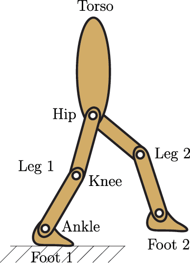
A model of bipedal walking robots

Compliant components of human foot

A model of robotic foot mechanism with compliance
Secondly, if such a compliant foot mechanism shown in Fig. 3 is attached to bipedal legs, we can make a walking model of bipedal robots with compliant feet as shown in Fig. 4(a). Then, for the purpose of compliant walking analysis, we attempt to obtain the joint torque and work according to the reaction force at the foot space of the bipedal robot as shown in Fig. 4(a). In the usual walking process of bipedal robots, if a vertical force fL is applied to ankle A as shown in Fig. 4(b), the corresponding reaction force is generated in the plantar surface contacting with the ground. In particular, the reaction force can be classified by two types, as shown in Fig. 4(b). One reaction force is made by the rigid link l1 of the truss and the other is determined by the spring. In practice, the front part of the foot is extended to the x direction when the foot is touching the ground, and the spring forming the tie-rod of the truss saves the tension energy made by its stiffness. This tension energy increases gradually by the structural change of the foot mechanism and it makes the additional reaction force supporting the truss. Thus, the determinant of the z-directional reaction force at the ankle fr can be represented as follows:

A walking model of bipedal robots with compliant feet: (a) lower body and leg mechanism with a compliant foot (b) compliant motion of the supporting foot and its reaction.

where the z-directional reaction force of each link and the corresponding joint angles are determined by


here fL is the –z-directional force given at the ankle. Additionally, the –x-directional force made by the spring fk is determined as follows:

where k denotes the stiffness coefficient of the spring.
Physically, the reaction force fr in (1) affects the motion of the joints of the leg. If it is excessive, the leg mechanism can suffer serious damage. So, knowing the impact of the reaction force is helpful for us to manage the actual walking motion of each leg. In this sense, the corresponding torques at the knee and hip joints according to the reaction force, τ H and τ K , can be determined as follows:


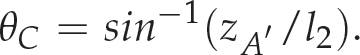
where θ* can be determined by


Finally, according to the virtual work principle [20], the corresponding works at the knee and hip joints according to the reaction force, wK(t) and wH(t), can be expressed as follows:


where
Note that the work expressions in (13) and (14) are useful for determining the corresponding work at the joint space of the compliant legs according to the reaction force which is propagated from the foot space. They can also be applied to analysing the performance of comfortable walking by the bipedal robot.
This section illustrates the exemplary simulation results obtained when analysing the work at the joint space of the compliant leg mechanisms of the bipedal robot when doing certain walking motions.
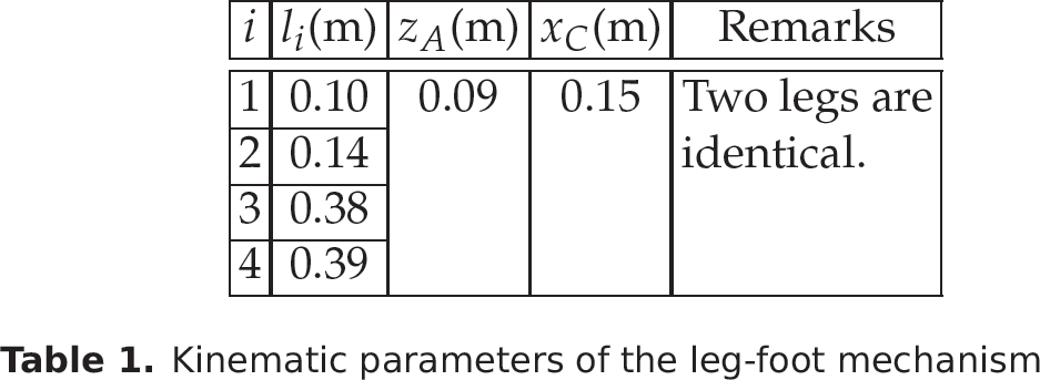
For effective simulations, the following conditions have been considered. There is no slip between the supporting foot and the contact surface. The tension of the spring used in the foot mechanism is available for the shock loads of the assigned walking, and if the waking load is removed, the extended stretch of the spring returns to the initial state. The vertical motion of the hip is only considered in Fig. 4. The kinematic parameters of the leg-foot mechanism have been assigned as shown in Table 1, where the initial position of the front part of the foot xC is determined by the initial configuration as follows:
Kinematic parameters of the leg-foot mechanism
Kinematic parameters of the leg-foot mechanism

where the truss angles θ B and θ C have been determined by (4) and (7).
Through exemplary walking simulations, we attempted to show the reaction force patterns according to the load pattern prescribed at the ankle. The corresponding joint torque and work profiles at the knee and hip joints of the compliant legs according to the reaction force which is propagated from the foot space have also been presented. Since the two bipedal legs in Fig. 4 are usually identical, the motion style of each leg has been considered as the same. So, we mainly demonstrate the simulation results for the walking of the right leg.
Fig. 5 shows a sinusoidal motion pattern assigned for the simulation study, and the distance function between the ankle and the hip h(t) is predefined as follows:

Motion pattern of the right hip for a periodic walk

where h0 is the initial distance between the ankle and the hip, and the parameter d adjusts the range of motion of the hip. Those parameters have been assigned as 0.74 m and 0.14 m by considering the normal human motion, respectively. Actually, such a motion pattern can be experienced in human walking [21]. In addition, the actuating range of the angle θ* at the right ankle for the given motion is shown in Fig. 6.
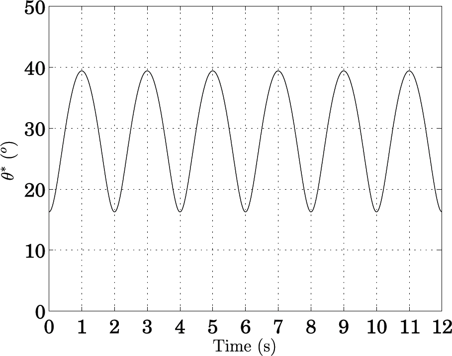
Trajectory of motion angle of the right ankle
Fig. 7 shows the z-directional force pattern loaded at the ankle by the given motion. This means that the normal force of −70 N has been considered periodically for each leg mechanism while walking. In practice, the vertical force pattern depends on the mass of the robot body and the acceleration of the leg motion while walking. But for effective work analysis, we prescribed such a maximum force pattern during the walk period. In this case, the trajectory of part A of the ankle in the xz plane has been assigned as shown in Fig. 8(a). Fig. 8(b) represents the motion pattern of A on the trajectory when the spring coefficient k is set as 700 N/m, and it is given by

Vertical force pattern given at the right ankle
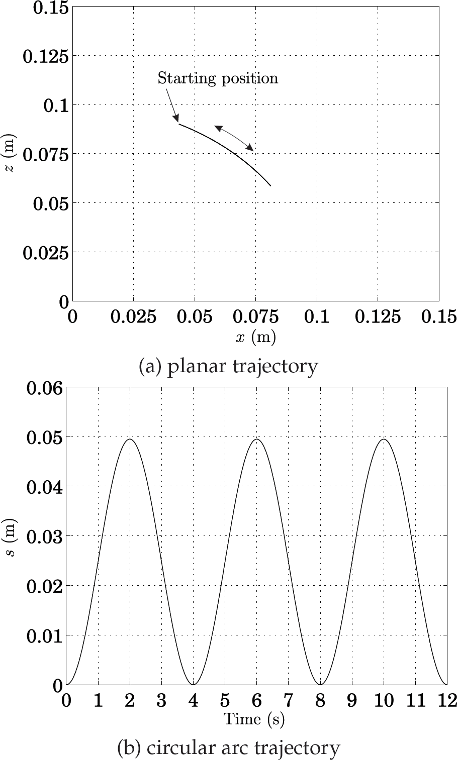
Trajectory of the right ankle

where sf is the total movement of the motion trajectory and it depends on the stiffness of the spring. For instance, if the normal force fL is −70 N and k is assigned as 1750 N/m, 1050 N/m, or 700 N/m, sf can be differently determined by 0.0227 m, 0.0363 m, or 0.0495 m, respectively.
In this simulation, we considered four cases of the plantar spring with the following stiffness: (a) k=∞ N/m, (b) k=1750 N/m, (c) k=1050 N/m, and (d) k=700 N/m. This approach is valuable for us to confirm the systematic influence of the reaction force depending on the compliance of the foot mechanism during the walking process.
According to the simulation, the two reaction force patterns determined by the link l1 of the truss and the spring, respectively, have been shown in Fig. 9. We can see in Fig. 9 that the magnitudes of those patterns are dependent on the level of the stiffness of the spring, but their trends are similar. In particular, the reaction force by the truss link is decreasing in the stepping range of 0∼2 s, 4∼6 s and 8∼10 s for each gait, and the reaction force by the spring is increasing relatively in the ranges. The reaction force by the truss link does not exist when the foot has been lifted in the range of 2∼4 s, 6∼8 s and 10∼12 s, and the reaction force by the spring dissipates gradually in the ranges. After all, the resultant reaction force is determined by adding these two terms, as shown in Fig. 10. It is worth noting that the reaction force at the moment of stepping can be reduced by employing such a compliant foot mechanism. In particular, Fig. 10(a) shows the reaction force at the ankle when the spring has no compliance (k = ∞ N/m), and Figs. 10(b), (c) and (d) show the reaction force patterns when the stiffness coefficients of the spring have been assigned as k=1750 N/m, k=1050 N/m and k=700 N/m, respectively. From Figs. 10(b)∼(d), we can say that a big-enough stiffness of the spring is appropriate for the robot to walk effectively after compliant foot landing.


The resultant reaction force patterns at the right ankle according to the stiffness of the spring: (a) k=∞ N/m, (b) k=1750 N/m, (c) k=1050 N/m, and (d) k=700 N/m.
The corresponding torques at the knee and hip joints according to the reaction force for the leg motion have been illustrated in Fig. 11. When the foot has a certain compliance, the joint torque at the moment of foot landing is relatively smaller than the stiff case. This means that the torque impact of each joint can be mitigated by employing such a compliant foot mechanism. It is also notable from Fig. 11 that the torque to take-off each foot from the ground can be adjusted by the level of the foot compliance.

The corresponding torque patterns at the knee and hip joints according to the reaction force at the ankle of the right leg: (a) k=∞ N/m, (b) k=1750 N/m, (c) k=1050 N/m and (d) k=700 N/m.
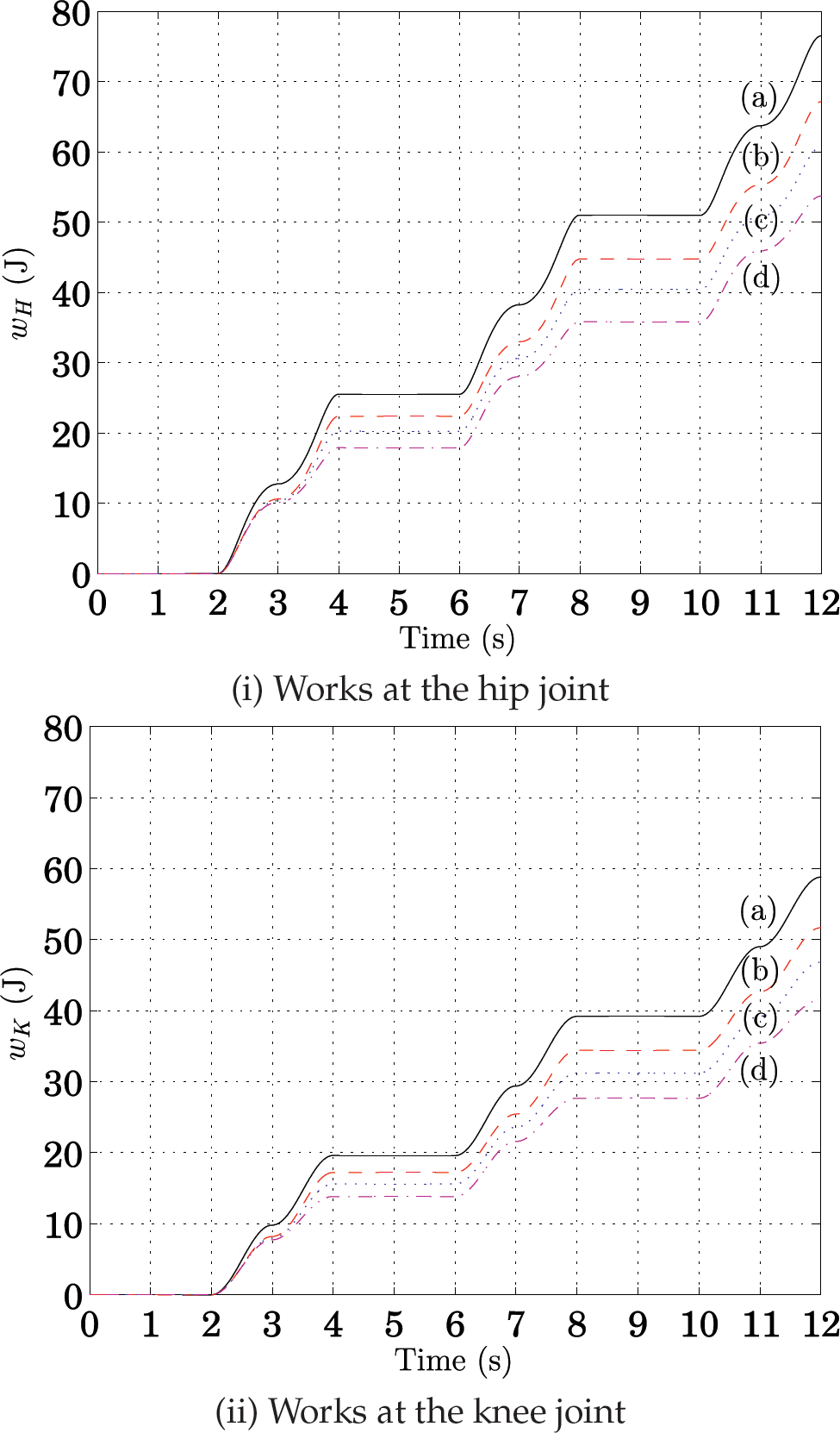
Next, for the work analysis at the joint space, the reference motion trajectories of the knee and hip joints for the assigned motion have been illustrated in Fig. 12. It has actually been pointed out in (13) and (14) that the work property depends on the style of joint motion trajectories. In this simulation, a smooth walking pattern has been considered for the actuation of the knee and hip joints. The resultant works accumulated at the knee and hip joints of the right leg for the walking motion have been presented in Fig. 13. To be specific, if the foot mechanism is stiff, the works accumulated at those joints are getting bigger as the time. When the foot mechanism has a certain compliance, however, the increment of the work can be moderated relatively. As the stiffness of the spring becomes smaller, the resultant work also becomes smaller gradually. This means that the foot mechanism with a compliance can contribute to reducing the joint work while walking. In practice, the work accumulated in those joints causes the fatigue of the leg as well as the entire robot system. Thus, it is noted that the fatigue at the joint space can be alleviated by employing such a compliant foot mechanism in a leg for walking. It is natural to experience such a fatigue phenomenon in the normal walking of a human. For instance, when we are walking wearing stiff shoes, the knee and/or hip joints may have a strong impact at each instance of stepping, and thus the body including the legs becomes tired gradually. In this sense, we need to select footgear carefully for good performance in professional or leisure sports.
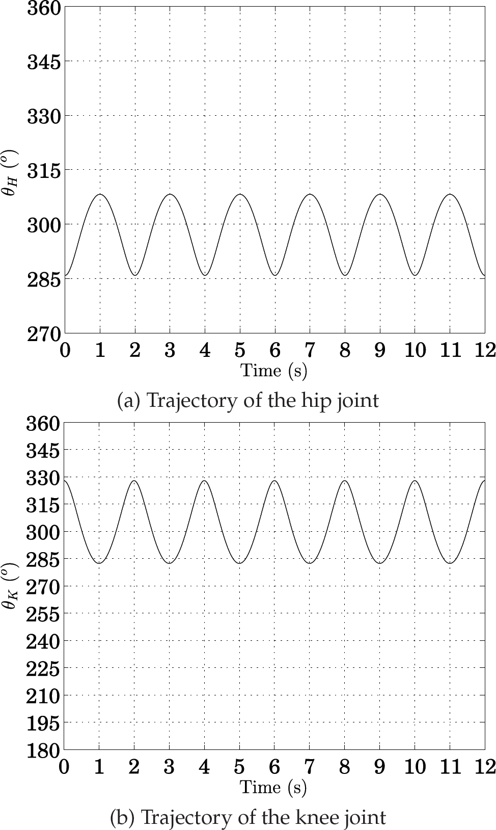
Trajectories of the knee and hip joints of the right leg

The corresponding works at the knee and hip joints according to the contact repulsion of the right foot: (a) k=∞ N/m, (b) k=1750 N/m, (c) k=1050 N/m, and (d) k=700 N/m.
In addition, we showed the resultant works accumulated at the knee and hip joints of the left leg for the assigned motion in Fig. 14. After the waiting time for the first gait, the responses of works at the joint space of the left leg are similar to those of the right leg.
The corresponding works at the knee and hip joints according to the contact repulsion of the left foot: (a) k=∞ N/m, (b) k=1750 N/m, (c) k=1050 N/m, and (d) k=700 N/m.
In practice, we need to manage the fatigue phenomenon of legs and body in order to walk for a long time. As shown in the simulation, it is notable that such a compliant foot mechanism specified in this paper can be applied to reduce the impact of the knee and hip joints at the moment of taking a step. Ultimately, this can contribute to alleviating the fatigue of the robot system while walking. The issue of reducing such impact is especially important in fast walking or running motions. In particular, effective fatigue management is very important for walking over long periods, in an irregular environment or when climbing steps [6–8]. Empirically, we can recognize that the comfortability of the general human walk depends on the shoes.
Consequently, through the work analysis, it is possible to give a guide to determine the compliance range of robotic foot mechanisms for comfortable walking. It is also expected that the convenience of various functional shoes for professional sports, as well as leisure sports, can be evaluated by using the work analysis. In addition, various walking patterns are also important for the work analysis of multi-legged robots [22].
The main conclusion of this study is that the walking fatigue of bipedal robots can be evaluated using the proposed work analysis, and the fatigue can be alleviated by employing a proper compliant foot mechanism. Through exemplary simulations using certain walking motions, the reaction force patterns at the ankle, the corresponding torques and works at the knee and hip joints according to the compliance level of the foot mechanism, and thus the effectiveness of such a compliant foot mechanism through the work analysis has been demonstrated. Additionally, the alleviation of walking fatigue of bipedal robots by means of a compliant foot mechanism was analysed. We finally conclude that the work analysis can be applied to determining a proper compliance of foot for the comfortable walking of bipedal robots, and that our analysis can contribute to characterizing the compliant features of footgear. It can also be applied to the development of a walking strategy for ensuring compliant walking.
As a future work, it would be very interesting to perform the work analysis with real hip and knee trajectories that present sharp transitions due to the contacts and impacts of the feet with the ground, and thus experimental evaluation is important. Considering the contact situations of each foot is also important for effective walking or running.
Footnotes
5. Acknowledgements
This research was supported by Kyungsung University Research Grants in 2013.