
Abstract
This paper presents a falling-based optimal foot trajectory planning method (FOFTP) for the effective walking of bipedal robots in three-dimensional space. Our primary concern is to determine the optimal footstep location for the more balanced walking of bipedal robots based on a measure of falling. A proper strategy for the intermediate trajectory of the swing foot is also considered. The feasibility of the FOFTP method is verified by a typical bipedal walking simulation. We also discuss the walking efficiency of the proposed approach. It is finally shown that the proposed foot trajectory planning method is applicable for the effective walking of bipeds or humanoid robots.
1. Introduction
It is well-known that the part of foot trajectory planning is crucial for the walking strategies of bipeds or humanoid robots.1–8 Thus, this paper concerns on effective foot trajectory planning which enables bipedal robots to walk in a more natural fashion.
In fact, there exist many kinds of walking patterns according to the given mobile manipulation tasks at hand. In order to plan a walking pattern of for bipeds or humanoid robots, the conventional zero-moment point approach has been employed by many researchers.9–11 This approach concerns on the trajectory of the body based on the reference trajectory assigned at the foot space. A predictive control approach for a walking gait's generation was proposed by Diedam et al.12 Their contribution is was to employ an adaptive foot positioning scheme in despite of its rather large computational costs to improve the dynamic balance in a the walking process. In order to compute the optimal sequences of footstep positions, some footstep planning approaches were presented.7,8 This approach is advantageous for footstep planning among obstacles. Also, there exist some gait generation approaches based on energy saving13 and gradient methods.14 On the other hand, Yun et al.15 recently presented a falling strategy for the safety of humanoid robots, where they addressed on a falling direction change for effective falling through a stepping approach. Since safety is the primary issue for humanoid robots to freely exist in human space and a fall from a walking posture can cause damage to the robot as well as to delicate and expensive objects in the surroundings or human beings, it is quite remarkable to consider the deliberate falling problem for a safe fall.16 In this sense, a predictive control considering viability can be a useful approach for safe and effective locomotion.17 Also, some types of measures have been proposed for balance in bipedal walking.18,19 However, comprehensive studies of bipedal walking pattern generation considering falling remain rare. Thus, we pay attention to a simple measure of falling to identify a more effective walking configuration for bipeds or humanoid robots.
The objective of this paper is to present a falling-based optimal foot trajectory planning method for the effective walking of bipeds or humanoid robots, where a new measure of falling is employed for this purpose. This paper is organized as follows. In Section 2, we specify a virtual-legged walking model of bipedal robots. A falling-based optimal foot trajectory planning method is described in Section 3. In Section 4, simulation results for bipedal walking are shown to illustrate the feasibility of the proposed foot trajectory planning method. Finally, concluding remarks are drawn in Section 5.
2. Modelling of Bipedal Walking Robots
In the field of bipeds or humanoid robots, shown in Figure 1, foot trajectory planning is fundamentally important for effective walking and manipulation tasks. To deal with such an effective bipedal walking problem, we consider a bipedal robot simplified as in Figure 2(a) and we also make a virtual-legged (VL1 and VL2) walking model for the bipedal robot, as shown in Figure 2(b).

A humanoid robot, WABIAN-2R3

An effective model of bipedal walking robots
In this paper, the virtual-legged bipedal model is used to identify the outstanding characteristics of bipedal robots in terms of balanced walking. Such a form of bipedal walking is usually performed by using one of the two legs alternatively. If a leg moves, the other leg should support the robot system to achieve the desired walking gait. The position of each foothold might have a serious effect on the balance of the robot system in the walking process. As such, in order to confirm such bipedal motion factors, we describe the force relationships of the bipedal walking mechanism, shown in Figure 2(b), as follows:


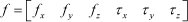
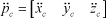
where m, ẍc, ÿc and z̈c represent the total point mass, the x-, y- and z-directional accelerations at the centre of mass (COM) of the robot system, respectively. The parameters fx and fy denote the force components for the robot in going towards the x- and y-directions and fz implies the vertical supporting force for the robot. The parameter g(=9.8m/s2) represents the gravitational acceleration coefficient.
Also, the x-, y- and z-directional moments observed at the centre of the sole, τx, τy and τz, can be represented by:


where these moments are to be activated by the reaction force and the gravitational force. The parameters xc, yc and zc represent the moving trajectory of the COM of the body of the robot in the x-, y, and z-directions, respectively. The corresponding directional position of the i-th supporting foot is denoted by xfi, yf and zfi. In practice, those components enable us to know the importance of the current foot position for effective bipedal walking.
By rearranging the force and moment relations given by (1)∼(6), we have a vector-matrix form of the dynamic equation, as follows:

where the generalized force vector f ∈ R6×1, the position vector of the COM pc ∈ R3×1 and its acceleration vector p̈c ∈ R3×1, the position vector of the i-th supporting foot pfi ∈ R3×1, and the gravitational effect vector d ∈ R6×1, respectively, can be expressed by:


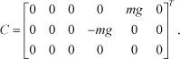
Moreover, the dynamic mapping matrix A ∈ R6×3, the mapping matrix between the position of the COM and the generalized force B ∈ R6×3 and the mapping matrix between the position of the supporting foot and the generalized force C ∈ R6×3 can be represented by:


From (7)∼(15), it is noted that the roll motion of the bipedal robot is affected by the y- and z-directional accelerations of the centre of mass and that the pitch motion is dependent on the x- and z-directional accelerations. They are also dependent on the relative locations of the supporting foot and the centre of mass. The yaw motion is especially dependent on the relative locations of the supporting foot and the centre of mass as well as the x- and y-directional accelerations. Since the relative distance between the supporting foot and the centre of mass is indispensable for the robot in walking, the yaw motion is a natural action when bipeds walk. Such a fluctuating yaw motion is experienced easily in the walking behaviour of humans. In the case of a walk with long strides, especially, those momental actions will be modulated significantly. In particular, excessive momental actions may give rise to the imbalance of the bipedal biped in walking.
As a result, it is noted that a strategy for effective footstep positioning can contribute ultimately to balance in bipedal walking.
3. Foot Trajectory Planning
This section describes a new foot trajectory planning method based on a falling-based optimization technique. Our approach has two methodologies to plan the swing foot's trajectory, as follows. One is a footstep planner, where an optimization technique using a measure of falling is used to determine the upcoming footstep location of the swing leg. The other is a trajectory planner to determine the intermediate location between the starting position of the swing foot and the upcoming footstep position assigned by the footstep planner.
3.1 State of Falling
For a new foot trajectory planning method, we first define a falling concept for bipedal robots. Consider a walk volume Vc, shown in Figure 3, which implies the reachable region of the virtual leg mechanism on a walk. In practice, the virtual leg is reachable within the range of rmin ≤ r ≤ rmax due to the limitation of the real joint actuation of the bipedal robot. In this paper, the state of falling is defined as that state where the virtual leg has fallen down on the ground surface in the xy plane of Figure 3.
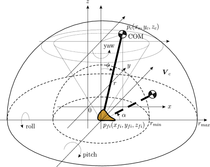
Walk volume of the virtual leg mechanism
Based on the definition of falling, the angle parameter φ in Figure 3 is directly related to the degree of falling of the robot. Accordingly, the angle is considerable as a simple identifier for the current state of falling of the robot. Table 1 shows the state of falling in the planar space. In addition, the direction of falling can be known by the yaw angle parameter α.
Classification of the state of falling

3.2 Optimal Foot Trajectory Planning Method
The foot trajectory planning problem considered in this paper can be depicted as Figure 4 and its actual goal is to determine the optimal footstep location providing support for the robot to walk along the trajectory prescribed in the COM space. This approach is meaningful for the task-based mobile manipulation of bipeds or humanoid robots, and it is different from the conventional ZMP-based methods.10,11 In order to plan the swing foot's trajectory, we propose a new footstep planner using an optimization technique based on a measure of falling.

Foot trajectory planning of a bipedal robot
In addition, we use a trajectory planner to determine the intermediate location between the starting position of the swing foot and the upcoming footstep position assigned by the footstep planner.
In fact, many kinds of approaches can be used for the second purpose. In this paper, we utilize the conventional cubic trajectory planning method which is useful for a single smooth motion.20 By using the cubic trajectory planning method, it is possible to generate a certain directional trajectory u as follows:

where t represents the time variable and the coefficients ai(i = 0, …, 3) are given by a0=si, a1=0, a2 = 3(sf – a0)/t2
f
and a3 = −2(sf – a0)/t3
f
, where tf represents the ending time of the trajectory. The parameters si and sf denote the starting and goal positions of the trajectory. For convenience, the cubic trajectory function given by (16) can be rewritten by:

When the bipedal robot in Figure 4 lifts the left leg (VL2) to walk, the robot system is managed mainly by the right leg (VL1) for the desired walking motion. In such a walking situation, one of requirements for the robot is how to assign the next footstep location of the swing leg. For this, we propose an optimization technique using a new measure of falling.
The measure of falling proposed in this paper is as follows. It is defined as the total of the falling index for the foothold candidates selected at each stage of walking. In particular, the measure of falling Ifall,k for the k-th footstep within the available search space Vf is computed by:

where nc denotes the number of trajectory samples prescribed at the COM space and nf represents the number of the next footstep candidates for the swing leg. The parameter φmax is the maximum falling angle for a normalization and it can be set as 90o in the planar walking surface, as shown in Figure 3. The angle of falling φ
jk
is calculated by:

where rx,jk, ry,jk and rz,jk imply the x-, y- and z-directional distances between the j-th position of the COM trajectory and the origin of the k-th foothold candidate of the swing leg, respectively.
As a result, the proposed optimal foot trajectory planning strategy can be summarized as follows: find the upcoming footstep positions of the swing foot in the x-, y-and z-directions that minimize the measure of falling given by (18) for all the footstep candidates to support the COM trajectory, predefined at each stage of walking according to the given mobile manipulation task. If the goal position of the swing foot is accordingly determined at each starting moment of walking, the intermediate foot trajectory between the current foothold and the next foothold is generated by using the cubic trajectory planning method given by (17).
4. Simulation and Discussion
This section performs a simulation of a typical bipedal walking task using the falling-based optimal foot trajectory planning method described in Section 3 and it offers significant results to verify the feasibility of the proposed method.
4.1 Bipedal Walking Task and Foot Trajectory Planning
There exists a preferable walking style for bipedal robots to achieve a specific mobile manipulation task. It is highly dependent on the desired behaviour of the body. For an illustrative simulation, we predetermined a typical motion trajectory in the COM space for bipedal manipulation, as shown in Figure 4, and then tried to plan the foot trajectory providing for the desired COM trajectory. In order to assign the desired COM trajectory, we considered a human-like sequential walking style mimicking the normal behaviour of human walking.21 It is summarized as follows:
START. Homing action for the initial upright posture standing in a state of dual support (DS). Shift the body to the right for the shifting time tshift while maintaining DS. Lift the left foot and move it to the next foot position for T–tshift by keeping the right foot support (RS), where T is the time period for one step motion. Shift the body to the left for tshift while maintaining DS. Lift the right foot and move it to the next foot position as with the third phase. If the walking task is finished, STOP after homing. Otherwise, return to the step 3.
Figure 5 shows the motion trajectories prescribed in the COM space for a bipedal walking simulation considering the human-like walking style. Specifically, in order for the robot to take a step forward, the x-directional trajectory of the COM xc was assigned as Figure 5(a). It was made by using the cubic trajectory planning method given by (17), where the size of movement at each step is updated by as much as 0.08m. Figure 5(b) shows the y-directional trajectory of the COM which has been planned by employing (17) properly as the corresponding section. The words RS, LS, and DS imply the state of the robot system supported by the right, left, or both feet, respectively. The time period for one step motion was set arbitrarily as 1s. The parameter tshift represents a time zone for the body to shift while maintaining the posture of dual support. It is actually helpful for an effective walk, where it was set as 0.4s. In fact, the robot takes a step forward after the shifting time. The z-directional trajectory zc was also assigned by employing (17), as shown in Figure 5(c). Of course, the trajectories specified in this paper can be formed differently according to the bipedal manipulation task as given.

Motion trajectories prescribed in the COM space for bipedal manipulation, where the assigned homing action to adjust the initial posture of the robot is performed until 1s.
Next, we describe the results of foot trajectory planning for the walking task given by Figure 5.
Figure 6 shows the resultant trajectories of the two feet planned for x-directional motion, where the circle ‘o’ indicates the upcoming footstep location of each foot planned by the optimization technique using the measure of falling given by (18). For the purpose of the optimization, the size of each walking step has been assigned as the same size of movement of the body at each step. We considered twenty footstep candidates at each step and twenty trajectory samples of one step motion at the COM space. That is to say, the parameters of nc and nf in (18) have been assigned for the optimization as an arbitrary value of 20. By using those parameters, each walking and motion step has been divided by the same distance. Figure 7 shows the profiles of the measure of falling checked in the process of walking. They have been used to determine the corresponding x-directional footstep location for the periodic bipedal walking and, from Figure 7, it is possible to identify the optimal footstep location for continuous walking. Physically, the selected footholds are optimal in terms of the overall balance at each stage of walking. The intermediate trajectory of the swing foot has been determined by (16). From Figure 5(b) and Figure 6, it is confirmed that there exist three modes of walking, namely RS, DS and LS.

Trajectories of the two feet planned for the x-directional motion: (a) left foot and (b) right foot.

Identifying the corresponding optimal footstep location at each stage of walking based on the measure of falling: (a) xf2 =0.12m (left foot), (b) xf1 =0.2m (right foot), (c) xf2 =0.28m, and (d) xf1 =0.36m.
Since the assigned task is a kind of straightforward bipedal walk, the y-directional trajectories of the two feet have been planned as yf1 =-0.089m and yf2 =0.089m, which are initialized for the right foot and the left foot, respectively. The z-directional trajectory of the swing foot has been planned as Figure 8. It was made by a kind of half-sine function activated at each step of walking.

Trajectories of the two feet planned for the z-directional motion: (a) left foot and (b) right foot.
4.2 Results of Walking Simulation
To illustrate the feasibility of the falling-based optimal foot trajectory planning method, we performed the three-dimensional walking task assigned in the previous section. For this simulation, we employed the bipedal robot system shown in Figure 9.

A bipedal walking robot used in the simulation
The robot system consists of five rigid links, such as a torso, two thighs, and two calves. It has twelve degrees of freedom: two for each hip, one for each knee, and three for each ankle. There exists a roll and a pitch joint at each hip, a pitch joint at each knee, and three joints for the roll, pitch and yaw motions at each ankle. Table 2 shows the physical parameters of the robot system. The position of the centre of mass indicates the distance measured from the ground when the robot is standing straight at in the initial state.
Physical parameters of the bipedal robot

The control block diagram for the bipedal walking task is shown in Figure 10. The walking pattern generator (WPG) in Figure 10 has two roles. One is to prescribe the trajectory(scd) in the COM space shown in Figure 5 and the other is to generate the trajectory of each foot sfd required for the robot in following the trajectory prescribed in the COM space. For the walking control of the robot, we employed a typical proportional and derivative joint controller with the gain matrices of Kp(∈ R12×12) = 
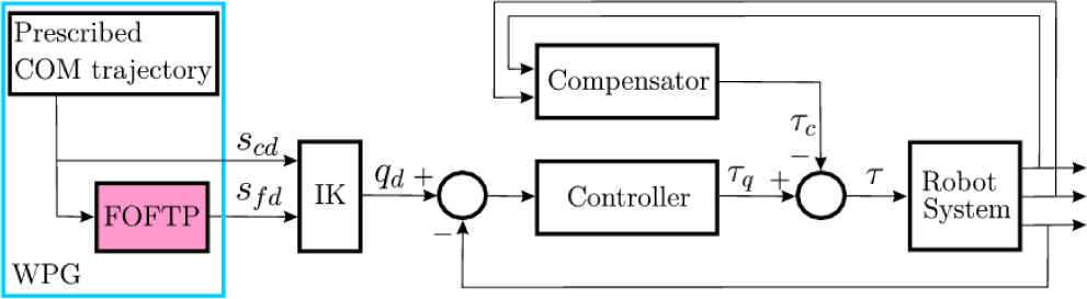
Control block diagram for the bipedal walking task
where Dh(∈ R12×3) denotes the dynamic translation matrix relating the hip space to the joint space, and φ(∈ R3×1) and ω(∈ R3×1) represent the Euler angle and the angular velocity vectors of the torso, respectively. The total inertial tensor represented in the hip space Ih(∈ R3×3) has been set by
Figure 11(i) shows the trajectory tracking result for the three-dimensional walking motion in the COM space of the bipedal robot. The performances in roll and pitch directions have been plotted in Figures 11(ii) and (iii).

Trajectory following result for the three-dimensional walking motion in the COM space, where the section between ‘o’ and ‘x’ implies the homing action for the initial configuration of the bipedal robot: (a) desired trajectory and (b) actual trajectory.
To be more specific, we can confirm the reasonable x-, y- and z-directional motions in the COM space by Figure 12. The stage up until t=1s in Figure 12 represents the homing action assigned for the robot in taking its initial posture. In particular, the z-directional motion is an important pattern for bipedal robots in exhibiting more natural walking behaviour. In the conventional study on the walking pattern generation of a bipedal robot,11 however, the body motion was confined to the two-dimensional space only and, thus, such a vertical motion – as shown in Figure 12(iii) – occurring in the normal walking of bipeds or humanoid robots cannot be observed. Recently, the issue of stable bipedal walking has been addressed.22 However, the motion in the sagittal plane was limited by using a radial bar. In this case, the rolling motion created by the y-directional shaking cannot be considered and the complete stability of the bipedal walking may not be analysed. This is because the physical moments generated by the walking style can have a serious impact on the walking balance of the bipedal robot system.23
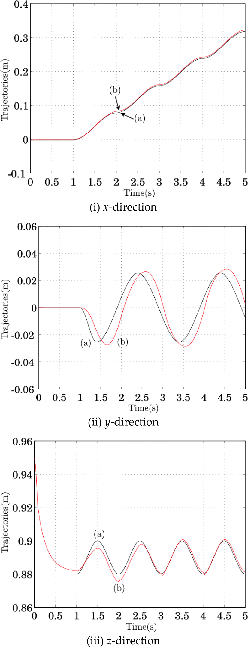
Trajectory following results in the COM space: (a) desired trajectory and (b) actual trajectory.
From Figure 13, we can also confirm the successful x-, y-and z-directional walking trajectory results of each foot for the given task. Figure 14 shows the satisfactory trajectories of the knee joints of the robot for the given walking task. We can also confirm that the step motions of walking are reasonable by observing the pattern of the vertical reaction force of each foot, as shown in Figure 15.
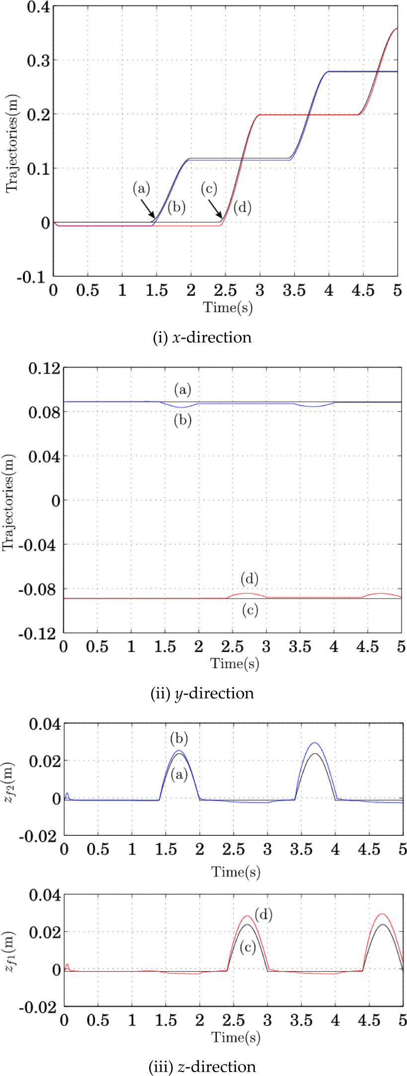
Trajectory following results of the two feet: (a) desired trajectory of the left foot, (b) actual trajectory of the left foot, (c) desired trajectory of the right foot, and (d) actual trajectory of the right foot.
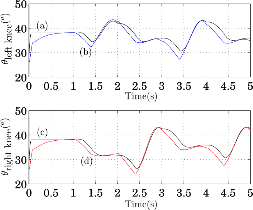
Trajectory following results of the knee joints: (a) desired trajectory of the left knee, (b) actual trajectory of the left knee, (c) desired trajectory of the right knee, and (d) actual trajectory of the right knee.

Reaction force of each foot on the z-axis: (a) left foot and (b) right foot.
Next, and in order to show the walking efficiency of the proposed approach, we performed an additional simulation by only changing just the landing positions of the swing foot, as in Table 3. The first case is based on the proposed optimal foot trajectory planning method and the second case is seeks to assign the landing position of the swing foot in near the optimal position arbitrarily.
The landing locations of the two feet for the walking task

Figure 16 shows the measures of falling- given by (18) – evaluated by this simulation, where the measure by of the proposed optimal case is more or less than that of the case 2. This means that the overall balance of the walking configuration planned by the proposed method is basically better.

Comparison of the measure of falling, where ‘o’ indicates case 1 (proposed case) and ‘x’ is case 2.
Since the knee joints play an important role to in supporting the bipedal walking motion, identifying the torque profiles of the knee joints is also valuable to in analyze analysing the walking efficiency of the proposed approach. In this sense, we especially notably showed the torque profiles of the knee joints for the given walking task, as shown in Figure 17. The sections of A, B, and C in Figure 17 indicate the ranges that the swing foot is maintained after touch down on the ground and the corresponding leg mechanism should support the motion of the walking system. As a result, we can confirm that the torque of the knee joint in the case 1 is more or less than that of the case 2, particularly especially in those supporting situations indicated by A, B, and C. This implies that the walking planned by the proposed approach is more efficient in terms of the energy required in by the knee.

Torque profiles of the knee joints: (a) torque of the left knee for case 1 (proposed case), (b) torque of the left knee for case 2, (c) torque of the right knee for case 1, and (d) torque of the right knee for case 2.
Through the simulation, it is confirmed that the simulation robot walked stably from the responses in Figure 11, and from Figures 12 and 13 the resultant tracking performances of the walking task are satisfactory. According to (7)∼(13), it is actually possible to moderate the momental actions of the bipedal robot system by optimizing the location of footholds. Thus, it is noted that successful results could be obtained by taking the optimal footholds for bipedal walking. In addition, the y- directional foot step planning is also important for the side walking of bipedal robots. It can be achieved by the same procedure as described in this paper.
5. Concluding Remarks
This paper presented an optimal foot trajectory planning method for the effective walking of bipedal robots, where a new measure of falling has been used to estimate optimal footholds. The feasibility of the proposed foot trajectory planning method has been verified by simulations for a typical bipedal walking task. The simulation results showed the successful tracking performances of the bipedal robot for the given walking task and the walking efficiency of the proposed approach has been confirmed. It is also confirmed through the simulation whereby the falling-based foothold searching technique is useful for identifying a more effective walk configuration in terms of balance. Consequently, it is expected that the proposed foot trajectory planning method can be applied to bipedal robots for effective walking and manipulation.
In addition, a proper consideration of an irregular walking surface will be an important matter for more natural bipedal walking and the running pattern of bipedal robots will be interesting for further study.
Footnotes
6. Acknowledgements
This work was supported by the National Research Foundation of Korea grant funded by the Korean Government (NRF-2010-013-2010-1-D00023).