
Abstract
Both body undulation and caudal fin flapping play essential locomotive roles while a fish is swimming, but how these two affect the swimming performance and hydrodynamics of fish individually is yet to be known. We implemented a biomimetic robotic fish that travel along a servo towing system, which can be regarded as “treadmill” of the model. Hydrodynamics was studied as a function of the principal kinetic parameters of the undulatory body and caudal fin of the model in a self-propelled condition, under which the time-averaged measured axial net force becomes zero. Thrust efficiency was estimated from two-dimensional digital particle image velocimetry (DPIV) measurements in the horizontal and mid-caudal fin plane. The Single-Row Reverse Karman wake (2S) is commonly observed in many previous studies of live fish swimming. However, we show that a Double-Row Two-Paired vortices (2P) wake was generated by the robotic model for most kinetic parameter combinations. Interestingly, the 2S wake emerged within the results of a narrow range of robotic caudal fin pitch angles (0<0<10°), occurring concurrently with enhanced thrust efficiency. We also show that, compared with the effect of body wavelength (?), the wake structure behind the robotic swimmer is more sensitive to the Strouhal number (St) and caudal fin pitch angle (θ).
1. Introduction
Fish have a number of swimming modes that are worth considering for emulation, but the locomotion that has long attracted the attentions of both biologists [1] and engineers [2]–[5] is the Body/Caudal fin undulatory kinematics. Many papers have addressed the live undulatory locomotion of fish over the past few years. But studying how fish generate the external fluid force to swim has proven to be difficult and is limited in the ability of controlling for parameters in a precise and repeatable manner. There still exists several important questions about kinematic effects on the hydrodynamics [6]. In many previous studies of fish swimming, the fish undulatory body and flapping caudal fin kinematics are treated together as a derivable mathematical wave [7][8]. Nevertheless, recent biological findings indicate that the caudal fin undergoes complex kinematics independent of the body in lots of bony fishes [6]. Both body undulation and caudal fin flapping play essential roles while a fish is swimming. How do these two parts inference the hydrodynamics of the fish individually? To what extent does each part of these two contribute to the over-all swimming performance? In addition, how is the wake flow generated as a function of the precisely controlled kinematics of the undulatory body and the flapping caudal fin? The questions presented above are certainly not the only possible ones worth discussion, but can serve as a starting point for thinking about.
Understanding how different locomotion of swimmers affects their thrust performance requires qualitative hydrodynamic experiments [9]. Simultaneous measurements of the hydrodynamic quantities (the fluid power, thrust force and self-propulsive speed) are strongly recommended [10]. The promise of robotic models for studying the biomechanics of locomotion in fishes has just begun to be realized. The robotic model offers a complementary approach to studies of living organisms by allowing precise control of the motion, accurate measurements of the forces and the exploration of a range of kinematic parameter spaces broader than that which exists in nature, also including kinematics that are not commonly used by live swimmers [10]. Both biologists and Engineers are particularly interested in how robotic swimmers quantitatively interact with their surrounding fluid environment. Through many studies on fish biomechanics [9], one significant technological development stands out. By seeding particles in water and shooting a laser sheet behind the swimming fish or robotic model, we were able to quantify hydrodynamic variables and flow patterns directly by using Digital Particle Image Velocimetry (DPIV) [11]–[15].
The quantitative thrust efficiency (t) and self-propulsive swimming speeds (U) are commonly considered as two important metrics for the hydrodynamic performance of a man-made machine [1]. In the present study, we designed a robotic fish model that is fixed on a towing system, which can be regarded as a running “treadmill” for the model and allows for swimming in a self-propelled condition. A digital particle image velocimetry (DPIV) technique was applied to quantify the flow field behind the robotic swimmer. We systematically examined the hydrodynamic performance of the robotic fish as a function of several principal kinetic parameters: Stouhal number (St), undulatory amplitude (h), body undulatory wavelength (A) and the caudal fin pitch angle (0). Through these, the hydrodynamic effects of the body undulation and the caudal fin movement on the overall self-propulsive performance can therefore be individually examined.
2. Materials and methods
A. Experimental apparatus and self-propulsion method
Fig.1 shows the schematic overview of the present experimental apparatus for the hydrodynamic experiment. The servo towing system is driven by a 4,000 watt AC motor and has a travel distance of 7.5m. Underneath the towing system is a water tank measuring 7.8mx1.2mx1.1m. The robotic fish moves at mid-depth in the tank to avoid the interference effect of the free surface and the bottom of the tank. As Fig.1a shows, the robotic fish and its mechanical transmission part are fixed under the force transducer. A low-drag streamlined strut penetrates the water and connects with the head of the fish. The external force of a robotic fish can be measured using a multi-component piezoelectric force transducer (Kislter 9254C). The output of the external Kislter transducer is recorded by Computer I through a data cable using a Controller Area Network (CAN) bus.
In the present experimental method, the self-propulsive speed is applied under a constant towing speed U when the thrust force is balanced by the drag force, namely when the average time net axial force Fx that acts on the robotic fish, measured by the force transducer Kislter 9254C, is zero. If this equilibrium condition is violated, the robotic fish would accelerate or decelerate under the action of the excess net force. To achieve the self-propulsive condition, we fix the robotic fish motion and vary the towing speed U until the time-average net axial force (during one beat cycle) measured by the force transducer is zero. In such a case, the external tether (i.e., the strut in the current apparatus) would have no effect on the time-averaged thrust force. The robotic fish will therefore swim at a self-propulsive speed and satisfy the self-propulsive condition.
The DPIV system, which was fixed on the carriage (as can be seen in the schematic view), was used to measure the flow field generated by the robotic fish. A high speed CCD camera (100 fps, 1024 pixels × 1024 pixels, Mintron Inc.) with an optical band pass filter is used to capture the particle image of the flow field. The laser beam (4W) with a wavelength of 0.532 μm is expanded by two cylindrical lenses to generate a light sheet that is reflected successively by three mirrors into the water tank and passes through the midline of the caudal fin of the fish. The wake is visualized by seeding the water with nylon particles (40–70 μm, 1.05 g cm3) to reflect the laser. This resulted in the successful illumination of the captured area by the bright laser light sheet. We then used the ‘mpiv’ Matlab toolbox, which is open-source software and was successfully tested in our previous biological studies [15]. As shown in the dashed blue box in Fig. 1a, when the experimental apparatus was in operation we were able to simultaneously record the power measurement system, DPIV system, force transducers that were mounted on the carriage running in the axial direction with speed (denoted by U), the data of the power and the flow field of the robotic fish. A snapshot of the apparatus in operation is provided in Fig. 1b.

(a) Schematic overview of the experimental apparatus. Under condition of self-propulsion, the time-average thrust force and drag force are balanced. (b) Snapshot of the experimental robotic model with laser system working. (c) High-speed camera recorded image. The white dashed box indicates the captured area of the particle images and the upward and downward flick indicates the side-to-side movement in reality.
B. The Biomimetic robotic fish and kinematics
The mackerel (Scomber scombrus), a typical carangiform fish, which is included in the Body/Caudal fin swimmers, is selected to be the mimic in present study. The robotic fish has a total length of 588mm, weighs 2.79kg and is a relatively exact replica of the mackerel (Scomber scombrus), whose biological data has been sufficiently provided by biologists [16]. As can be seen from Fig. 2, multilink mechanical skeletons make it possible for the robot model to have a fish-like undulation with the form of an actual fitting curve [17]. The undulating mechanism was a high-precision assembly of 4 links made from anodized aluminium and covered with foam and a special waterproof structure made of Silica. Each mechanical link was capable of relative rotation with respect to its neighbouring link and was driven by a brush servo-motor Maxon RE40, mounted on a metal plate above the water. All mechanical links were simultaneously controlled by a motion coordinator, Trio MC206. Details of the robotic swimmer's implementation were also discussed in our previous paper [15].
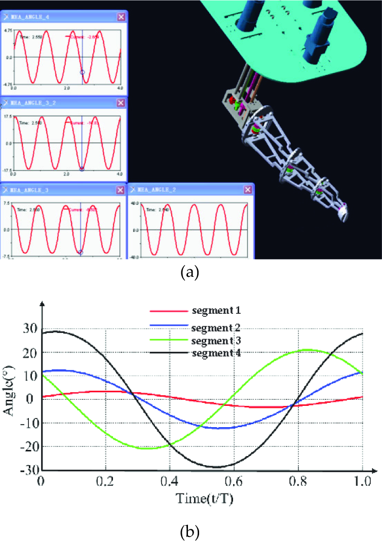
(a). Simulation of the robotic links in ADAMS. (b) Angles for different discrete segments.

(a) (b) Robotic fish body undulation at instants of t=1 T /3, t=2T /3, and (c) (d) the midline curves of posterior 2/3 of the robotic fish undulation during one tail beat.
To study the hydrodynamic effect of the robotic swimmer as a function of the Stouhal number (St), undulatory amplitude (h), body undulatory wavelength (A), the caudal fin pitch angle (0) and the parameter range should be appropriately set to make the kinematics relevant to the live fish locomotion. The locomotion of the Body/Caudal fin undulatory fish can be classified into three general “modes”: anguilliform, carangiform and thunniform. These three modes can be represented by particular fish specimens: the eels, mackerels and tuna separately (Shadwick et al. 2006). Given that the anterior of the present robotic swimmer's body (roughly one third of its total body length) is mechanically rigid in the present robot, all undulatory movements start from one-third of the body length, measured from the nose of the robotic fish. The posterior body parts (anterior to the caudal peduncle) of the robot were programmed to swim with the wave equation:

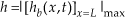
h(x,t) denotes the displacement along the lateral direction in a body-fixed coordinate system. x denotes the displacement along the main body axis. It should be noted that x is measured from 1/3L of the robotic fish. L represents the total length of the robotic mackerel's body, c denotes the chord length of caudal fin, k=2π/λ denotes the wave number, ω denotes the circular frequency of oscillation and ω=2πf; c1 and c2 are applied and adjusted to achieve a specific value for the amplitude envelope of the body. While considering the caudal fin motion, the heave and pitch motions of the caudal fin can be denoted as:

Where h(x,t) again denotes displacement along the lateral direction in a body-fixed coordinate system, hc and θ c denote the heave and pitch motion, respectively, c denotes the chord length of the caudal fin, f represents the flapping frequency, Ψ is the phase angle between the heave and the pitch motion and x=L−2c/3 denotes the position of the caudal fin centre of mass, which connects the caudal peduncle. θ max represents the pitch angle amplitude of the caudal fin.
Fig. 3a and 3b show snapshots of the undulating robotic fish in two instances. We digitalized the midline of the robotic fish body from a bottom view in Matlab (the robotic fish is upside-down). Fig.3c and 3d show the midline curves of imposing programmed kinematics on the robotic mackerel's body. Note that only the posterior 2/3 of body moves. Midlines at equally spaced time intervals throughout a tail beat can be observed. Each time this is shown in a distinct colour. The movement of the robotic fish is quite relevant to the kinematics of the live swimmer (more live fish body midline images can be referred to Fig. 11.1 on page 427 of [1]).

(a) Schematic views of single-row and double-row vortices. (b) Three dimensional vortex model and laser sheet. Different colours indicate the distinct directions of vortex rotation, and the arrow indicates the direction of the jet flow.
According to the study of Tytell [18], the wavelength of typical anguilliform kinematics is about 0.65L. While for carangiform swimmers, the wavelength is 0.95L, which is reported by Hess and Videler [16]. The wavelength (λ=1.25L) of the yellow-fin tuna (Thunnus albacares) reported by Dewar [21] can be used as a representative for the wavelength of the thunniform kinematics. In the present study, we systematically varied the wavelength at increments of 0.1L between λ=0.65∼1.25L, as can be seen from Table 1. The pitch angle θ of the caudal fin can be described as the angle between the line from the leading to the trailing edge of the robotic caudal fin and the free stream flow (in the forward direction). The X-ray scan results of intervertebral bending angles of chub mackerel and Kawakawa tunas by Dickson showed that the pitch angles (θ) are 20.5° and 11.5° for carangiform and thunniform kinematics, respectively, while a pitch angle of 26.5° is employed by the anguillform kinematics reported by Tytell [18]. In the present study, systematic tests were performed for a number of fixed caudal fin pitch angles, with increments of 5° between 0∼40° (see Table 1 for notation).
Parameters of undulation kinematics
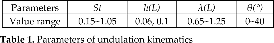
From Table 1, systematic tests were also performed for the Strouhal number, which were varied in small increments from 0.15 to 1.05. This St range is sufficiently large to cover all prior biological observed results [19]. The undulating beats were cycles of 0.8 Hz in the flow, with a speed of U=0.09 ∼0.62 m/s. These operation conditions corresponded to a St ranging over 0.15∼1.05. We also decided to conduct tests at two fixed dimensionless undulatory amplitudes (h): h=0.06, 0.1L.
Previous experimental studies of the flapping foil [19] and the swimming live fish [9] show that the hydrodynamic performance of fish locomotion is dominated by the fundamental dimensionless parameter (the Strouhal number), which is defined as:

where h denotes the undulating amplitude of the caudal fin tip:
where |·|max denotes the maximum absolute value. The Reynolds number (Re) is defined as:

where L represents the length of the fish, and v represents the kinematic movement viscosity of the water. In this paper, the mean quantities of force, thrust, power and efficiency are obtained by averaging the instantaneous values over several undulatory cycles of robotic fish. To preserve the relative proportion of the power and thrust force between the present experimental results and previous research, we non-dimensioned these qualities. The thrust coefficient can be defined as:

where ρ is the density of the fluid and T is the thrust force estimated by the flow field (see equation (9) and (10) for notation). U denotes the towing speed of the guide rail. The power coefficient can be denoted by:

Pfluid denotes the time-averaged fluid power (see (5) for notation). Uncertainties in the measured quantities are defined as the standard error of the mean:

where σ is the sample standard deviation for each data point consisting of N measurements, and N=5 in this study. The error bars in some of the rest figures reflect the uncertainties.
C. DPIV and thrust force estimation
To measure the flow field and then calculate the thrust force of the swimming robotic fish using a two-dimensional approach, the laser sheet plane of the DPIV system should be set to pass through the midline of the Homocercal caudal fin of the robotic fish. The midline was recommended as the best horizontal position for conducting two-dimensional wake measurements [9]. The depth of the three-dimensional vortex rings (see Fig. 3a for notation) effectively equals the caudal fin's height, while the measurement planes at other horizontal levels underestimate the thrust force.
The vortex ring model, which assumes that all the impulse shed by the robotic fish is contained in elliptical vortex rings, is used for the analysis of the wake [24]. The measured wake then allows us to use 2D vortex dynamics theory to compute the impulse of the fish. We form the flow field from several tail flap cycles by freezing each vortex in its shed position and then take measurements of the wake. There should in fact be two different types of wake structures generated by the robotic swimmer. This point was confirmed in the current experiment. In Fig. 3b, the distribution and morphology of the vortices are provided in a three-dimensional way.
Illuminating a cross-section through the three-dimensional vortex ring yields a flow pattern consisting of two vortices. The location of the vortices in the velocity fields was determined by plotting the contours of vorticity. The morphology of a vortex is described by the vortex centre, the core radius R0, the ring radius R and the jet angle α (see Fig. 4b for notation). The impulse (I) of a vortex ring can be calculated by (9) according to the Mine-Thomson principle:

where p is the density of water and Γ is the mean absolute value of the circulations of the pair of vortices. A is the elliptical area surrounded by the vortex ring which can be derived from the vortex ring radius R and caudal fin height s:A = πRs/2. The total force was resolved geometrically using the jet angle to determine the axial component of force. The vortex dynamic model and the computing method for the two types of vortices are different. For single-row vortices, as can be seen from Fig. 4a, the vortex rings form a linked chain and only one vortex ring (i.e., two vortices in the two-dimensional plane, which are denoted by vortex 1, 2) was generated in a flapping circle. The time-averaged thrust force T is denoted as:

where f is the flapping frequency of the robotic fish. For the double-row vortices (see Fig. 4b for notation) the robotic fish generates two vortex rings (i.e., four vortices in the two-dimensional plane, which are denoted by vortex 1∼4) during a flapping circle. The time-averaged thrust force T is:

where α1 and α2 denote the jet angle for two vortex rings. Details of the calculation of thrust force using the vortex dynamic model can be referred to in our previous study on live fish. The thrust efficiency is defined following Lighthill [23]:

Pfluid indicates the pure fluid power consumption, obtained by subtracting the mechanical transmission power from the total power. More details can be referred to in our previous study [12].
3. Experimental Results
A. Self-propulsive speed result
From Fig. 4a it can be seen that as the St Increases, the time-averaged axial net force F̄x gradually increases from negative to positive values. This phenomenon indicates the transition from a mean drag type net force to a mean thrust type net force.

(a) Strouhal number (St) effect on the net force and Amplitude effect on U; (b) Caudal fin pitch angle (θ) effect on the St and U (m/s); (c) Wavelength (λ) effect on the St and U.
The point at which the Fx curve crosses zero (i.e., the self-propulsion line, as shown in Fig. 4a) is the point at which the mean drag force is exactly balanced by the mean thrust force. The St at this point therefore indicates the Strouhal number at which the self-propulsion speed U is obtained and we denote this special St as St*, which indicates the “self-propulsion Strouhal number”, while the remaining St are denoted without the asterisk. From Fig. 4a, it can be observed that the absolute value of the higher amplitude (h=0.1L) is obviously larger than that of the lower amplitude (h=0.06L) at almost the same St by a considerable margin. The cases for the lower amplitude h with higher frequency f finally results in a smaller self-propulsion St than that of the opposite case, i.e., a robotic fish swimming at h=0.06L will be faster than one at h=0.1L.
Recalling previous biological studies (Hess and Videler, 1984), the live mackerel vary their flapping amplitude h as they change their swimming speed U. An interesting question has been posed by both biologists and robotic researchers: if the St is kept constant, which is more important for the thrust performance of robotic (or live) fish, the frequency f or the amplitude h? Using the self-propelled swimming speed as a metric, it appears that frequency is more significant than amplitude when St is constrained to a fixed value. From Fig. 4b, we can observe that the maximum self-propulsion speed was recorded at θ=25°, which is U=0.237m/s, corresponding to a St of 0.397. As can be seen from Fig. 4c, the self-propulsive speed increases as wavelength increases.
B. DPIV Flow field and wake structure
Fig. 5 shows the DPIV time-series of the flow field that is generated by the robotic swimmer at h=0.1, λ=0.95, θ=20°. The tail performed a flick to its right side and then another to its left and each flick of the tail generated a vortex ring. As shown in Fig. 6a, vortices 1 and 2 were generated from the downward flick (towards the right in reality) and formed the vortex ring R1 at 0T. The vortex ring is denoted by the dashed red ellipse. While at t=T/2, it can be observed that vortices 3 and 4 were generated from the upward flick (towards left in reality) and formed the vortex ring R2. The vortex rings R1 and R2 are characterized by lateral divergence and then spread away from the body axis in a wedge-like arrangement. The current experiment yields a high Reynolds number (104<Re<105), so the vortices diffused in the far wakes and only the near wake can be visualized.

Flow field of the robotic swimmer with kinematics parameters of h=0.1, λ=0.95, θ=20° under self-propulsion state, where St=0.43. The dark drawn line indicates the position of the caudal fin. (a)∼(f) show the vortices and flow vectors at six different time stages of one beat: 0T∼5T/6 with equal interval.
Figure 6(a) is a main schematic depiction of the wake generated by the current robotic model and summarizes our experimental findings of wake geometry. By varying the kinematic parameters we visualize a variety of wake structures, including the Von Karman structure, Single-row Reverse Karman wake (2S), Two-Paired vortices (2P) wake and Two-Paired and Two-Single vortices (2P+2S) wakes from the characteristic of the near wake flow. Present results showed that the near flow wake structure is less sensitive to the wavelength λ and heave amplitude h of the fish undulatory locomotion. We mapped out the wake type in a diagram spanned by the St and θ in Fig. 6b within 0 ≤ St ≤0.6 and 0°≤θ≤40°, where wake transition points of the robotic model are also summarized.

(a) The DPIV results of different wake structures generated by the robotic model. Panel A∼D show the vortices and flow vectors at the same instance of one tail beat, where t=T/2. (b) (St, θ) phase space that summarize the wake structures and transitional points of robotic model.
To explain the general trend in wake transition observed in this study, the lowest St region (0<St<0.15), the classic “Von Karman Vortex”, can be observed within St<0.15 and is denoted by region A, where the model didn't generate any thrust wake, but rather a drag wake. A slight increase in St in region B (0.15≤St≤0.325), the typical “Reverse Karman Vortex Street”, was observed. This means that a slight increase in St promoted the creation of a 2S wake (0.15≤St≤0.325) before giving way to a 2P wake structure at the higher St (0.325<St<0.5), where a thrust type wake began to be generated. Region C, which is contained in the limits of 0.325≤ St ≤0.5 and 10°≤θ≤30°, is characterized by the formation of clear paired vortices. Considering a whole beat circle, the wake structure can be viewed as a Two-Paired vortices (2P) wake. As the shedding vortices from the caudal fin tend to have a larger lateral velocity component, which advects them away from the midline of the body and causes them to spread in a lateral direction. We speculate that, the wake splits laterally, therefore the 2P wake emerges.
A very interesting result can be observed. Within the range of 0.325≤ St ≤0.5, the wake structure transits “back” to “Reverse Karman Vortex Street”, while the caudal fin pitch angle amplitude was within the range of 0°≤θ≤10°. Recall that recent computational and biological results indicate that the wake structure of fish-like locomotion depends primarily on the Strouhal number [7].
Nevertheless, present DPIV results showed that both the caudal fin pitch angle and the Strouhal number had a significant impact on the wake structure. Additionally, we found a Two-Paired and Two-Single vortices (2P+2S) wake structure in region D, also from the characteristic of the near wake flow. Despite the fact that some previous studies on flapping foils showed the wake transition [25], those experiments are not conducted under the condition of self-propulsion. Also, the isolated performance of a flapping foil cannot fully represent a swimming fish's, especially the body/caudal fin kinetic pattern that characterizes approximately 88% of extant fish families [8].
C. Thrust efficiency
Fig. 7 shows the estimated thrust efficiency η as a function of the St (see equation (12) for notation of St). The results show that a negative thrust efficiency appeared at St<0.15. The orientation of vortices in the wake can be used to demonstrate whether thrust or drag is being produced by the bio-robotic system. Recall the wake structure results in 3.2, a classic “Von Karman Vortex” was also observed in this St range. It caused a velocity deficit in the wake and produces drag, therefore yields negative thrust efficiency. Then the thrust efficiency increased rapidly as St increased. A peak thrust efficiency of 32.8 % was recorded at h=0.1L, St=0.325. Then the thrust efficiency decreased gradually with increasing St, within the range of 0.35<St≤1.025. Experimental results obtained at the amplitude of 0.06L (i.e., h=0.06L) show that a peak thrust efficiency of 20.4 % was recorded at St=0.325. For the case of h=0.1L, the peak thrust efficiency is higher (32.8 %), but is also obtained at St=0.325. Namely, the robotic fish with larger amplitude (h) is more efficient than the one with lower amplitude. This result agrees well with studies on the flapping low aspect-ratio foil [20]. Additionally, it should be noted that the optimal thrust efficiency for both amplitudes fell within the range of 0.3≤St≤0.325. Nevertheless, the St of the robotic swimmer under a self-propulsive condition fell outside of this optimal region (St=0.375 for h=0.06L, St=0.43 for h=0.1L).

Thrust efficiency as function of Strouhal number
Fig 8a demonstrates that the peak thrust efficiency was 38.1%, recorded at 0=10°. The thrust efficiency decreased as 0 increased within the range of 25°<θ<40°. At 0=40° the thrust efficiency reduced to a minimal value of 13.6%. It is quite interesting that the peak self-propulsion Strouhal number (St), which corresponds to the maximum self-propulsive speed of the robotic swimmer, was recorded at 0=25°. The present experimental result can be interpreted as follows: the high thrust efficiency and large self-propulsion speed of the robotic swimmer cannot be yielded at the same caudal fin pitch angle. Additionally, the data in Fig. 8b show that both the thrust efficiency and self-propulsion speed increased as body wavelength increased from 0.65L to 1.25L. A maximum thrust efficiency of 41.0% was obtained at A=1.25L.

(a) Thrust efficiency and Self-propulsion St* as function of caudal fin pitch angle θ. (b) Thrust efficiency and Self-propulsion St as function of undulatory body wavelength λ.
4. Discussion
To our knowledge, there exist very limited publications that report the quantitative hydrodynamic performance of the freely swimming robotic fish. The only relevant study is conducted by the Techet group [26], who applied DPIV to characterize the swimming performance of a complaint fish-like robot. The midline kinematics result of the robot showed that the undulatory body and the caudal fin formed a derivable mathematical curve. The drawback of this work is that the robot is made of a continuous flexible body so the body and caudal fin cannot be individually controlled. The minimal St, which corresponds to the maximum swimming speed of the robot, turned out to be 0.7 [26]. In comparison, current robotic model results in a minimal St of 0.375. This in turn indicated that a faster swimming speed can be obtained by allowing the body and caudal fin motion to be individually controlled.
We also showed that the wake structure of the robotic model depend strongly on the Strouhal number and caudal fin pitch angle. For robotic fish swimming in a self-propelled condition, the caudal fin pitch angle proved to be an essential factor governing the transition of the wake structure and the thrust efficiency. The body wavelength, which also affects the thrust efficiency, however, does not have a significant effect on the wake structure. The reverse Karman wake is produced by many fish species and physical systems, such as the oscillating thrust-producing foil moving steadily forward [19] and during the caudal fin locomotion by bluegill sunfish (Lepomis macrochirus), giant danio (Danio malabaricus), mullet (Chelon labrosus) and trout (Oncorhynchus mykiss) etc [24]. However, the reverse Karman wake only emerged within the results of a narrow range of robotic caudal fin pitch angles, occurring concurrently with enhanced thrust efficiency.
Note that, in the current study, we use a two-dimensional planar technique at the mid-span of caudal fin for investigating a variety of principal parameters relating to undulatory propulsion in fishes. Present data would be difficult to obtain directly from studying live fishes. The wake flow in aquatic locomotion appears to be affected by a three-dimensional fluid effect. Three-dimensional PIV techniques, such as volumetric imaging, should be applied to understand the fluid physics of fish locomotion, which would possibly reveal new features of fish locomotor dynamics.
5. Conclusion
Robotic techniques are becoming increasingly important in the field of biomechanics [27]. They offer the opportunity to focus research by creating robotic models that cannot be easily controlled with the desired kinetic mechanisms. In this paper, we simultaneously measured the power consumption, self-propulsion speed and wake structure of a robotic model. Results show that the wake structure is more sensitive to the caudal fin pitch angle (θ) and Strouhal number (St), but less sensitive to the body wavelength λ. As reported by previous studies [7], the Strouhal number has already been found to have the dominant role on the wake structure behind the fish. However, present results showed that the pitch angle also has a remarkable impact on the wake structure of the undulatory propulsion. More details of the vortex dynamics and mechanical properties of the robotic fish will be reported in future communication.
Footnotes
6. Acknowledgements
This work was supported by the National Science Foundation support projects, China (Contract No. 61075100).