
Abstract
Wall-climbing robots have extensive applications, however, no effective adhesion system has been designed for robots deployed in high-altitude, rough concrete buildings that are subjected to large wind loads and vibrations. This paper proposes a new suction method based on a mechanism utilizing hook-like claws and presents the design of a robot system for inspecting rough concrete walls. We present a method for describing the degree of concrete surface roughness. To study the stress imposed on the hook-like claws, we propose two types of mechanical models for the interactions between sharp claws and microprotuberances. The design method for the tips of the sharp claws is then established. Finally, an 8-foot wall-climbing robot based on a mechanism utilizing hook-like claws is designed and laboratory experiments on a man-made concrete wall are conducted. The results indicate that the low-cost system endows the robot with enhanced climbing stability and satisfies the inspection requirements for tower constructed by water brush stone or bricks.
1. Introduction
Wall-climbing robots have extensive applications in engineering. The analysis of adhesion methods (Table 1) indicates that traditional adhesion systems are confined to specific applications. Cracks on concrete walls can easily cause suction disc leakage and dust on wall surfaces may lead to considerably negative effects on bionic attachments. Traditional adhesion designs are therefore unsuitable for work on cracked or rough concrete surfaces, water brush stone, bricks and rocks, particularly those found on high-rise structures such as cable-stayed bridge towers and viaduct bridge piers. These structures are located in remote mountain areas that are characterized by strong wind conditions which cause robots to vibrate as they climb bridge towers. Such situations have created a high demand for more effective attachment devices. Inspection work on small cable-stayed bridges are manually conducted by trained workers who use hydraulic lifts or hanging brackets held by a steel rope (Figure 1(a)).
Comparison of the advantages and disadvantages of adhesion methods.


Manual bridge testing.
In this paper, we propose a wall-climbing robot based on a mechanism utilizing hook-like claws. The robot takes on risky tasks in hazardous environments and increases operational efficiency by eliminating the installation of costly scaffolding or dragging winches.
Similar suction methods or climbing mechanisms have been designed. Given the recent developments in nanotechnology and bionics, researchers have extensively exploited bionic technology to create attachments that replicate the functioning of animal feet; such attachments present excellent adhesion performance. The technology is also used to build various types of bionic climbing robots. Different attachment materials, including carbon nanotubes and polymer materials, were developed at Stanford University. An example of a robot made of such materials is Spinybot [1–4], a wall-climbing robot that imitates the wall-climbing mechanism of beetles. It can scale concrete and brick surfaces because the tiny barbs on its feet enable it to hook onto microprotuberances on rough wall surfaces. Using microspines that catch on surface asperities as bases, researchers proposed a spiny-based bio-inspired robot called RiSE for scansorial environments [5–6]. Using bionics, traditional design and module combination, manufacturers have built tree-climbing and ground-walking robots by combining six modules for legs. However, the robots manufactured by such methods require the use of numerous driving devices, which results in complex mechanical structures. Sintov proposed a hook-like claw-equipped wall-climbing robot called CLIBO [7], which can stay on a rough wall surface in a fixed posture for long periods. CLIBO can be used in monitoring, rescue, observation and entertainment applications. After studying the delicate structure, adhesion performance, and movement characteristics of gecko foot setae [8–9], Dai designed a gecko robot that can move freely in 3D space [10]. He also investigated the microstructure of the claws of hornets, beetles and other insects to design bionic feet [11]. When three tarsi are bent, sharp claws can hook onto inwardly and outwardly curved points on rough wall surfaces, so that the robot can hang onto walls and climb.
Many researchers have improved the vacuum suction mechanism to retain the advantages and eliminate the shortcomings of normal active vacuum suckers. Using a tracked wheel mechanism, Kim proposed a wall-climbing robot that features a combined suction and caterpillar system [12]. After a survey on natural creatures, Zhang presented a passive adhesion principle and designed a modular climbing robot [13]. He also proposed a series of pneumatic glass wall-cleaning robots for high-rise buildings [14]. Using gecko-like fibrillar adhesives, researchers designed a wall-climbing robot named Waalbot II and optimized it by incorporating autonomous adhesion recovery into the system [15]. Waalbot II can climb both non-smooth and inverted smooth surfaces. Using dry adhesion and 18 miniaturized motors, researchers designed a novel robotic platform, Abigaille II, which can climb vertical surfaces [16]. Using flat (non-patterned) and soft elastomer adhesive treads, Sitti proposed a tank-like climbing robot called Tankbot [17], which is lightweight and can climb on a slope of 0° to 360° on smooth surfaces.
Research on wall-climbing robots based on limb function has also been conducted and the robots built are used in industry. These robots include LEMUR II [18], which can autonomously climb vertical rock-like surfaces using its four limbs; a bionic modular robot based on the way a pair of claws functions [19]; ROCR, which can climb rough surfaces [20]; robots with feet that adhere onto walls [21]; and the Explorer™ family of pipe robots [23], Wind Power Tower Inspection and Maintenance Robot[24], and tree-climbing robot[24]. These robots, however, perform primarily climbing tasks on smooth surfaces or are used in low-altitude applications.
Given this backdrop, we propose a new suction method based on the mechanism of claws, analyse the surface roughness of the concrete wall, develop an inspection robot and conduct laboratory experiments to test the performance of the method and the robot. The rest of the paper is organized as follows. Section II presents the method for describing the degree of concrete surface roughness. Section III proposes the mechanical models of the interactions between sharp claws and microprotuberances, and analyses the maximum size of the tips of sharp claws. Section 4 discusses the 8-foot wall-climbing robot designed on the basis of a mechanism utilizing hook-like claws. Initial experiments are also presented in this section. Section 5 presents the conclusion and future work.
2. Method for Describing the Degree of Surface Roughness
A wall surface usually has many microprotuberances. For example, concrete is a complex material with cement mortar as its base and aggregate as support. After artificial processing, part of the mortar disintegrates and the aggregate is exposed, with a large amount of micropores and microcracks produced during hydration. Precisely describing a concrete wall surface through mathematical methods is difficult because of its complex surface microgeometry (Figure 1(b)).
For simplification, we introduce the concept of the degree of surface roughness. Characteristic parameters, including the height and transverse spacing of microprotuberances, are selected (outline linear roughness Ra and average width of outline unit Sm) to describe a wall surface. The shape of microprotuberances is simplified into either a hemispheroid or a cone for analysis [1], and serves as a foundation for establishing the mechanical models of the interactions between sharp claws and microprotuberances on the wall.
2.1 Roughness description method for hemispheroids
Figure 2(a) shows microprotuberances whose geometric centre is on the exterior base surface of the wall. Here, R is the radius of microprotuberances; h denotes the distance between the centre of the microprotuberances and the base surface of the wall; and S is the transverse spacing between the microprotuberances on the wall surface. The approximate relationship between the description parameters of microprotuberances and the characteristic parameters Ra and Sm of the wall surface is defined as follows:
Hemispheroid-shaped microprotuberances.

After determining Eq. (1), we obtain

Figure 2(b) shows microprotuberances whose geometric centre is on the internal base surface of the wall. The following equation is obtained:

After deriving Eq. (3), we have

2.2 Roughness description method for cones
Figure 3 shows a cone-shaped microprotuberance with outline linear roughness Ra; S is the transverse spacing between the microprotuberances on the wall's base; and θ is the angle of the microprotuberances. The approximate relationship between the parameters of microprotuberances Ra and Sm is defined as follows: S = Sm/2, θ = arctan[Sm/(4Ra)].

Cone-shaped microprotuberances.
3. Mechanical Models of the Interactions between Sharp Claws and Microprotuberances
After a long evolutionary process, climbing animals have developed claws with excellent tribological properties and microstructures, which serve as valuable models for bionic and tribological study. These bionic models provide significant contributions to the invention of wall-climbing robots.
3.1 Insect adhesion mechanism
The adhesion of sharp animal claws on rough wall surfaces is known as the linkage mechanism. The geometric size and friction coefficient of claws, as well as wall roughness, considerably influence the linkage effect.
In bionic technology, the linkage mechanism is important primarily in mechanical structure design. The adhesion effect depends on the interactions between hook-like claws and wall surfaces.
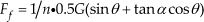
Figure 4 shows a schematic of the mechanism by which insects attach onto wall surfaces. G denotes gravity; F is the interaction force between claws and contact surfaces; Fn and Fs represent the two components of contact reaction force; α is the contact angle; C is the centre of mass; L represents the distance from the centre of mass to the wall surface; and D denotes the distance between the upper and lower claws. Under the pull of gravity, animals tend to slide down and tip over. Therefore, the friction Ff and adhesive force Fa between claws and wall surfaces are necessary for guaranteeing adhesion.

Schematic of the insect adhesion model.
According to the model of insect attachment on wall surfaces, the following balance equations are obtained: F = G / 2 cosα, Fn = 0.5G tanα, Fa = G / 2 and tanα = 2L/D. For creatures that climb in a prostrate position (e.g., insects and geckos), the smaller the α, the smaller the force F required and the easier the movement of animals on a wall surface.
3.2 Mechanical model of the interactions between sharp claws and microprotuberances
Hemispheroid-shaped microprotuberances effectively reflect wall surface geometry; thus, they serve as ideal models of microprotuberances on wall surfaces. On the basis of the adhesion mechanism of insects, we establish the mechanical models of the interactions between sharp claws and microprotuberances.
3.2.1 Interaction Model I
Model
When the centre of the circle of hemispheroid-shaped microprotuberances is on the external wall surface (Figure 5), a robot relies on the interactions between sharp claws and microprotuberances to maintain balance. For the upward tangential force along the wall surface and adhesion force perpendicular to the wall surface, we obtain the balance equations
Schematic of Model I.


where R is the radius of microprotuberances, r is the tip size of the sharp claws, h denotes the height of the microprotuberances above the base surface of the wall, θ is the contact angle between the sharp claws and microprotuberances, N denotes the supporting force, F f represents friction, and n is the number of sharp claws.
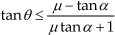
Using friction as a basis, we determine inequality as follows:

After deriving Eq. (11), we obtain

where α is the contact angle, determined by the centre of mass of the wall-climbing robot and the distance between the upper and lower hook-like claws; μ represents the coefficient of friction between sharp claws and the wall surface. The tip size of sharp claws is calculated using Eqs. (1), (2), (5), and (12):

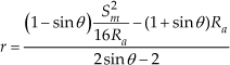
The equal sign in Eq. (12) indicates that the maximum size of the tips of sharp claws can be calculated as follows:

Analysis of maximum claw tip size
For the surface of a concrete wall, we consider the effects of various parameters on the maximum size of claw tips. These effects are discussed as follows:
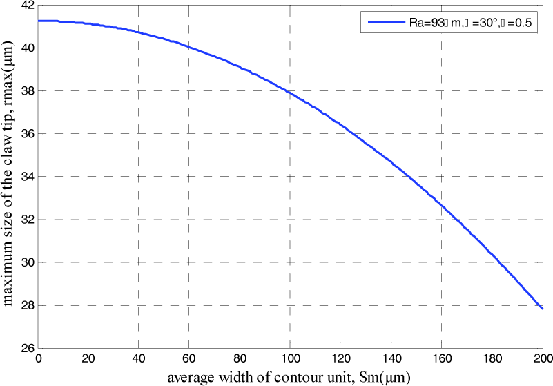
Sm – rmax relationship
In this relationship, outline linear roughness Ra = 93.0μm, contact angle α = 30° and friction coefficient μ = 0.5. The relationship curve of Sm – rmax (Figure 6) is obtained according to Eq. (14).
Sm – rmax relationship curve.
With other parameters given, the average width of the outline unit significantly affects the tip size of sharp claws: the larger the average width, the smaller the tip size of sharp claws. When the average width of the outline unit is much larger than the height of the microprotuberance, the wall surface is approximately smooth. Therefore, a tiny sharp claw cannot attach onto the wall surface.
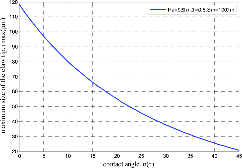
α – rmax relationship
Assuming that the average width of the outline unit is close to the height of the microprotuberance, and that Sm = 100μm, the relationship between contact angle α and maximum tip size rmax (Figure 7) is determined using Eq. (14).
α – rmax relationship.
Figure 7 shows that the contact angle considerably affects the tip size of sharp claws. The smaller the contact angle, the larger the maximum size of claw tips. In other words, the wider the allowable range of claw tip size, the easier the processing. When designing wall-climbing robots, therefore, the contact angle should be as small as possible. That is, the distance between the centre of mass of the robot and the wall surface should be minimized, and that between the upper and lower claws should be increased. This finding is consistent with the conclusion derived from the insect adhesion model and from the adhesion mechanism of animals. Generally, contact angle α is less than 45°.
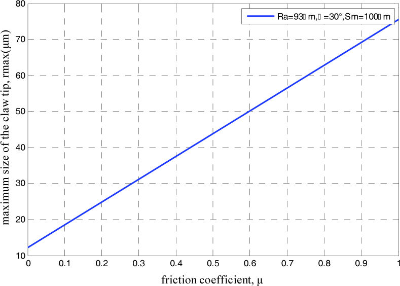
μ – rmax relationship
Figure 8 shows that because the coefficient of friction between sharp claws and wall surfaces varies for different types of wall surfaces, the relationship between the friction coefficient and the maximum size of the tips of sharp claws can be determined using Eq. (14). The figure also illustrates that the coefficient of friction between sharp claws and wall surfaces significantly influences the size of claw tips: the larger the friction coefficient, the greater the maximum size of sharp claw tips. Given that the friction coefficient is related only to the characteristics of a material itself, selecting the appropriate materials for claw tips is necessary to maximize the coefficient of friction between sharp claws and wall surfaces.
μ − rmax relationship.
Ra – r max relationship
When α = 30°, μ = 0.5 and Sm = 100μm, the Ra – rmax relationship can be obtained with Eq. (14), as shown in Figure 9. The figure indicates that the greater the Ra, the greater the maximum size of sharp claw tips. That is, the greater the height of the microprotuberance, the more prominent this microprotuberance is. The smaller the required claw tip size, the wider the variation range of sharp claw tips. When outline linear roughness is considerably smaller than the transverse spacing between microprotuberances, the wall surface is approximately smooth. Therefore, the robot cannot attach itself onto the wall, and the maximum size of the sharp claw tip in the Ra – rmax relationship curve has a negative value.
Ra − rmax relationship curve.
Relationship between Ra and S m – rmax
For the robot, both contact angle α and friction coefficient μ are selected in accordance with specific situations. The effect of the characteristic parameters (Ra, Sm) of the wall surface on the tip size of sharp claws should be comprehensively considered. When α = 30° and μ = 0.5, the relationship of Ra and Sm – rmax can be derived with Eq. (14). Figure 10 shows that when the ratio of transverse spacing to height is approximately Sm / Ra > 4, the maximum tip size of sharp claws is a negative value, and the wall-climbing robot cannot attach itself onto the wall surface. When 4 >Sm / Ra > 0, the smaller the Sm, the greater the Ra and the maximum tip size of sharp claws.
Relationship between Ra and Sm − rmax.
3.2.2 Interaction Model II
Model
When the centre of hemispheroid-shaped protuberances is on the internal wall surface (Figure 11), the following equations can be obtained according to the equilibrium relationship:
Schematic of Model II.


With Eqs. (15)–(18), we can derive

On the basis of friction, inequality is obtained as follows:
From Eqs. (3), (4) and (15), we derive
The equal sign in Eq. (21) indicates that the maximum tip size of sharp claws can be calculated thus:

Analysis of maximum claw tip size
On the basis of the same analysis method used in Model I, we obtain the following relationships: Sm − rmax relationship (Figure 12); α − rmax relationship (Figure 13); μ − r relationship (Figure 14); Ra − rmax relationship (Figure 15); and the relationship between Ra and Sm − rmax (Figure 16). The simulation results obtained from Model II are the same as those derived from Model I.
Sm − rmax relationship.
α − rmax relationship curve.
μ − rmax relationship.

Ra − rmax relationship.

Ra,S m − rmax relationship.
3.3 Comprehensive analysis
The comparison of Models I and II indicates the following results:
Although the heights of the microprotuberances above the base surface of the wall differ (+h in Model I and –h in Model II), the analysis results of the two models are similar. That is, the average width Sm of the outline unit, contact angle α, friction coefficient μ and outline linear roughness Ra significantly affect the maximum size rmax of claw tips. The smaller the Sm, the greater the maximum size of claw tips; the smaller the α, the larger the size of claw tips. The greater the μ, the greater the maximum size of claw tips, and the greater the Ra, the greater the maximum size of claw tips. In actual design, the effects of these four factors on the size of claw tips should be comprehensively considered. The maximum tip size of sharp claws is estimated according to Eqs. (14) and (23), through which the maximum size of hook-like claws can also be obtained.
4. Robot Design and Experiments
The main task of the robot designed in this study is to carry detection equipment for testing cable-stayed bridge towers. The height of a main large-scale bridge tower is generally greater than 200 m. The main tower of Sutong Bridge is 300 m high. Therefore, the bridge tower-testing robot is a typical high-altitude robot. In this section, the design system of the robot is introduced, the robot design is presented and the experiments are discussed.
4.1 Outline of the design system
Wall inspection robots are categorized under a specialized group of mobile robots whose main feature is climbing ability versus the weight of robot bodies and the resistance of wall fissures. Structural mechanism is the most critical component in a wall inspection robot system because this mechanism directly affects a robot's capability and technical index. The mechanism includes moving mode options and climbing plan design. Designers should consider not only climbing methods, as is done in conventional mobile robots, but also safety characteristics, such as anti-vibration and anti-wind loading, because these robots work at high altitudes. During robot design, therefore, the following requirements should be satisfied:
a robot mass of less than 2 kg and payloads below 1 kg to enable stable climbing along towers inclined at any angle;
a travel speed of 0-0.08 m/s, and once charged, the robot should be able to move over 500 m;
a maximum payload of 1 kg;
operational efficiency, in which the climbing robot should efficiently navigate on towers that are several hundred metres long;
noncomplex structure, that is, the robot should be small and lightweight, as well as consume little energy, to guarantee that it can be carried and mounted onto a wall surface by only one worker;
payload capacity, which enables the robot to carry non-destructive evaluation equipment and charge coupled device cameras or other devices.
Simple control options, convenience in carrying sensors and overall costs are the other primary factors.
The different movement modes of a special type of climbing robot (Table 2) are comprehensively compared and analysed in accordance with the above-mentioned requirements. Wriggling and crawler climbing modes present complex structures and high costs, and the wheel mode is difficult to incorporate into a hook-like claw design. Therefore, the walk mode is the most suitable for the structure of the bridge tower-testing robot.
Comparison of the advantages and disadvantages of different movement modes for special climbing robots.

4.2 Design of the wall-climbing robot based on a mechanism utilizing hook-like claws
On the basis of Models I and II in section 3, we design the claws and the wall-climbing robot.
4.2.1 The whole mechanism of the robot
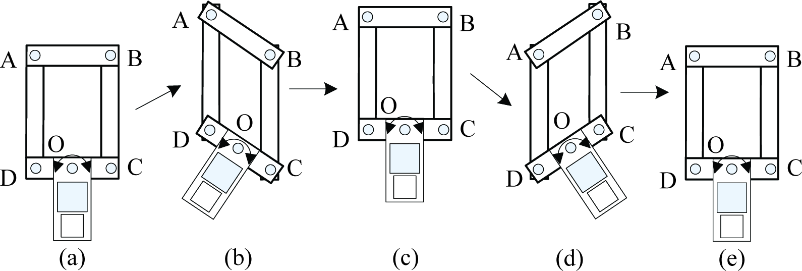
The principle that underlies robot function can be described using a parallelogram mechanism (ABCD in Figure 17). Four hook-like claw modules (1, 2, 3, 4) are connected to the rack (AD) of the parallelogram mechanism; hook modules 5, 6, 7 and 8 are fixed onto the rack (BC) of the parallelogram mechanism. The claw modules possess multi-fingered minute claws, which not only increases the torque handling capability of the robot, but also improves the adaptability of the claw to different wall surface. The parallelogram mechanism is driven by a main motor as the claw modules grasp microprotuberances on a wall. The main motor is installed on the fixed board at point O and swings the drive rod (CD) back and forth within a predetermined angle range. The two sets of hook-like claws move alternately up and down, pushing the robot up the wall. Using the parallelogram mechanism, the robot is more stable and can be driven using only one main motor which can be controlled easily.
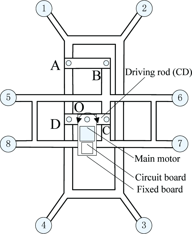
Climbing principle of the robot.
4.2.2 The structure of the claw
The structure of the claw can be seen in Figure 18. The steering engine is placed on the main body of the mechanism using a mounting plate. Through a steering gear shaft and a connecting rod, the steering engine drives some minute claws placed in the claw box. An extension spring connects the steering gear to the other end of the connecting rod, which makes the claws more flexible.
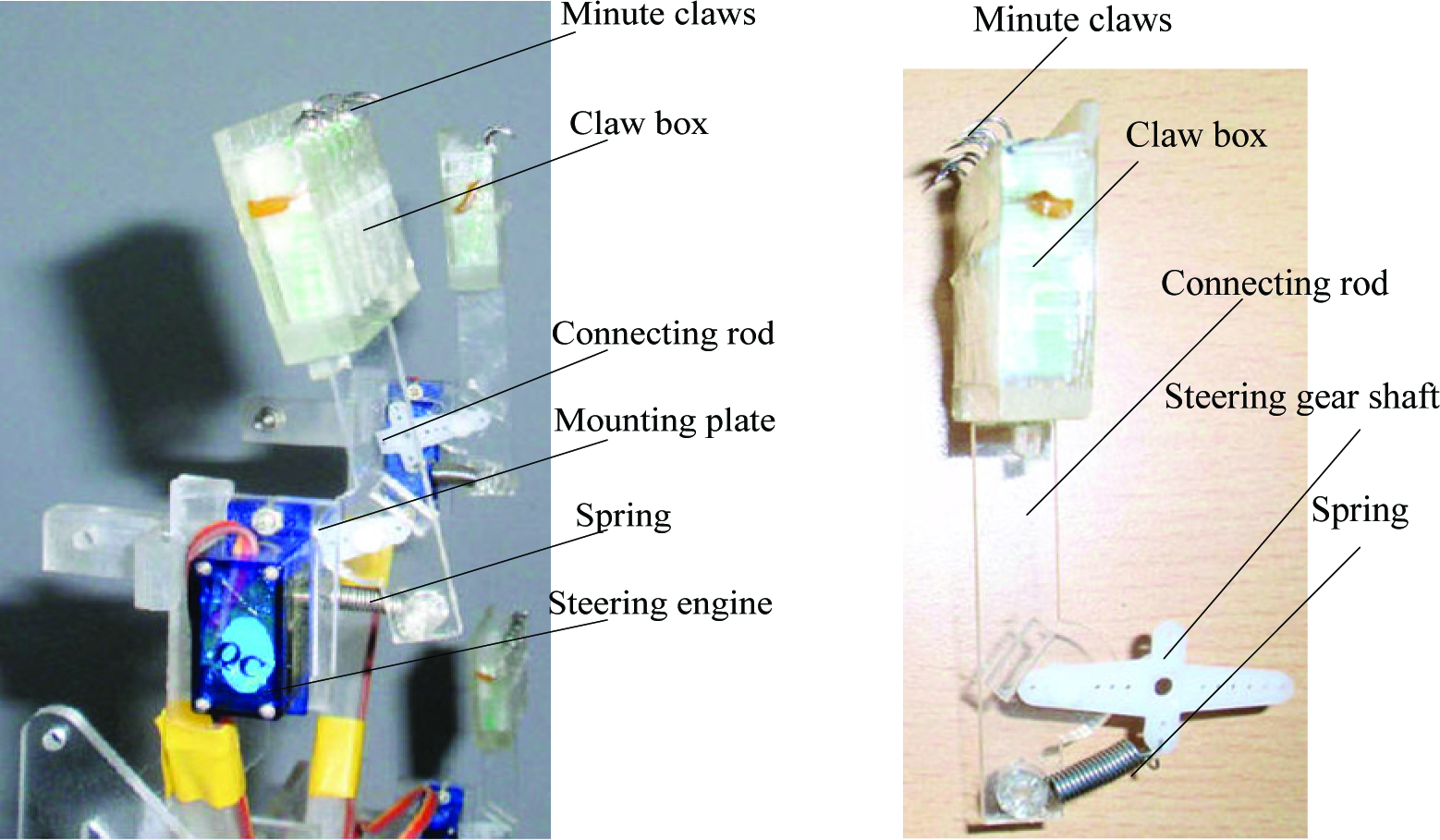
The structure of the claw.
When the microprotuberances make contact with the wall, the minute claw can slide along the surface from point M to N to search for the grasping point (Figure 19). In this process, the steering engine provides the clasping force of the claws. The extension spring pulls the other end of the connecting rod to guarantee that the minute claws make contact with the wall surface. One group of claw modules (1, 2, 3, 4) climbs up one step, the other group of claw modules (5, 6, 7 and 8) grasps the microprotuberances, and then the four steering engines (belonging to modules 1, 2, 3 and 4) turn inversely to release the claws. The claw modules then climb the next step.

Motion diagram of the claw.
4.2.3 Robot movement gait
As the robot is a parallelogram mechanism, it can be simplified to a quadrangle (ABCD), from which we can determine the climbing gait of the robot. When the robot climbs up vertically, the gait includes two steps, that is, the two edges move up alternately as shown in Figure 20.

Vertical movement gait
However, when the robot moves transversely, the steps are more complicated and the velocity is slow. The transverse movement includes four sub-steps, as shown in Figure 21, that is, one step of the movement is composed of two climbing sub-steps and two landing sub-steps. In this process, therefore, the efficiency is lower than in the upwards climbing modes. In this section, we only present the vertical movement gait and the horizontal movement gait. With the simple parallel mechanism, the robot can climb on an uneven bridge structure in all directions based on these movement gaits.
Horizontal movement gait
4.3 Experiments
In laboratory experiments, the inspection robot is designed using polymethyl methacrylate. It reliably performs on rough, inclined and vertical concrete walls, as well as on a soft cloth surface (Figure 22). These results indicate that the climbing ability of the robot satisfies the requirements for various wall surfaces, such as concrete, brick and sandstone.
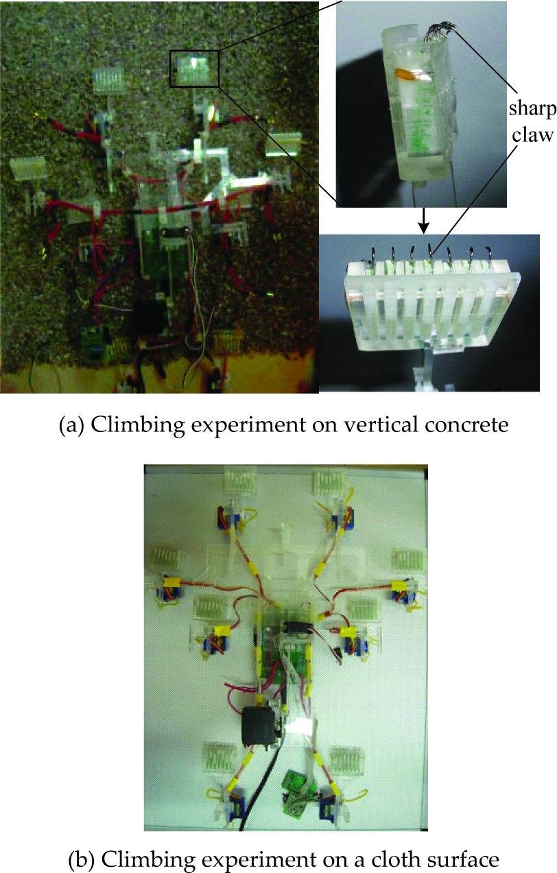
Climbing principle and experiments on the robot.
Several motion tests are conducted during the experiments. Steering and obstacle avoidance can be controlled, and the robot can move over small obstacles or gaps. The experimental results indicate that the robot can climb over obstacles smaller than 25 mm; beyond this value, the robot encounters difficulties.
The experiments show visible claw effects. The ascent and descent velocity of the robot can satisfy the demands of tower detection. Based on the results of the theoretical analysis and laboratory experiments, we conclude that the major technical parameters of the inspecting robot are as follows:
At payloads below 1 kg, the robot can climb along walls inclined at any angle.
The robot can be installed on a cable by only one worker.
Travel speed can be adjusted to a range of 0-0.08 m/s.
The maximum surmountable obstacle height is 25 mm.
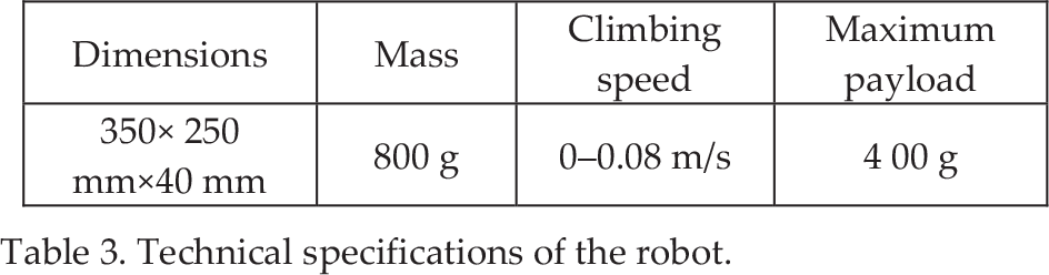
The main parameters of the robot can be seen in Table 3.
Technical specifications of the robot.
5. Conclusion
An innovative wall inspection robot based on the mechanism of hook-like claws was developed. The robot, composed of eight claws and a pair of driving mechanisms, can automatically inspect towers on cable-stayed bridges. The mechanical models of the interactions between sharp claws and microprotuberances were studied, and the stress imposed on hook-like claws was examined. The design method for the tip of sharp claws was established. We carried out experiments to test the climbing ability of the robot and the feasibility of the claws. At payloads below 1 kg, the robot can stably climb walls inclined at various angles and satisfy the initial requirements for tower inspection.
Enhancing the stability of the wall-climbing robot necessitates the resolution of the following problems: the mechanism of the interactions between sharp claws and wall surfaces should be determined, and the angle between the sharp claws of the robot and wall surfaces should be optimized.
Footnotes
6. Acknowledgments
This research is supported by the National Natural Science Foundation of China (51005046).