
Abstract
In order to meet the requirements of mechanization and automatic installation of high-altitude boards, a hybrid high-altitude board installation robot is designed. At the same time, a method based on screw theory is proposed to avoid the defects of kinematics analysis of robots using the traditional Denavit–Hartenberg parameter method. It is to construct a kinematic equation for the hybrid robot. According to the kinematics equation of the robot, the forward solution of the end-effector position is obtained. Besides, the workspace cloud image of the robot end-effector is worked out by MATLAB. By means of the equation to test the kinematics of the robot, the absolute error is 0.5 mm between the theoretical value and the actual value of the end-effector coordinate system position. It meets the national standard for board gaps. This study provides reference for subsequent research works on control technique and trajectory planning of the hybrid robot of high-altitude board installation.
Introduction
At present, the mechanization of China’s construction industry is much less developed compared with that of industrial powerhouses. The installation of high-altitude boards is mainly dependent on manual production. It is assisted by simple machinery. However, this construction process is burdened by higher labor intensity and higher risks. But the efficiency is low and the quality of the construction cannot be guaranteed. It is especially risky for the installation of large-scale boards because it involves more than a dozen of people and may lead to construction accidents. Therefore, we carry out researches on construction equipment and demonstration application of building materials. We aim to make China’s board construction more mechanized and intelligent, while reducing the labor intensity of workers, and increase the efficiency and quality of the construction. To this end, we try to study and develop a hybrid robot for high-altitude board installation in light of the characteristics of high-altitude board construction. According to the given joint angle or displacement, the robot’s forward kinematics should be defined for the position of the robot end effector. It is the basis for further research on robots and it is important for robot workspace analysis, trajectory planning, motion control, and error compensation.
Traditionally, Denavit–Hartenberg (D-H) parameter method 1 is used for conducting forward kinematics research on robots. However, it requires the establishment of a local coordinate system for each joint. The posture of each coordinate system differs according to joint types. When changes arise in the configuration of the robot, we will need a re-establishment of the coordinate system. In addition, the modeling process is geometrically complicated, cumbersome, and less meaningful.2–5 However, if the product of exponential (POE) is used to analyze forward motion which is based on the screw theory, we only need to establish the basic coordinate system S and the end-effector coordinate system T. 6 The establishment process for the coordinate system is simple and easy to understand. It fully utilizes the geometrical properties of robots and makes the exponential product formula (the method of screw) the best alternative to the D-H parameter method. 7
At present, scholars at home and abroad have done a lot of research on the application of the screw theory in the field of string and parallel robots. They have obtained many research results.8–13 Agrawal 14 used the reciprocal screw of each chain of the parallel mechanism to study the kinematics of the motion platform. He gained the input-output equations of speed and acceleration. It is beneficial to the subsequent parameter design based on the parallel performance index of parallel mechanism. Martínez and Duffy15,16 applied a spintronic algebra to study the tandem mechanism. Their representation is isomorphic with the Lie algebra se(3) of the special Euclidean group SE(3). Shi and Dai 17 and Zhao et al. 18 used the screw theory to study the parallel mechanism with less degrees of freedom. They analyzed the validity conditions of active joints of the mechanism. Z Huang et al. 19 applied the screw theory to analyze and synthesize the parallel mechanism. The system synthesis method lays the foundation for designs of new mechanism. W Chen and J Zhou 20 performed a kinematic analysis of a modular redundant robot by means of the screw theory. It simplifies the kinematics modeling process of modular robots with arbitrary degrees of freedom or configurations. FX Zhang et al. 21 used the screw theory to analyze forward kinematics of a closed-chain tandem robot. Thus, they proposed a method to gain a kinematics equation for the closed-chain cascade robot. It is based on the screw theory as well. According to existing results, the research and application in the field of hybrid robotic kinematics are less found. A general method for study and application has yet to be developed.
In this article, a hybrid robot for high-altitude board installation is introduced as a research object. 22 It is obtained by expanding the series structure on the parallel robot motion table. It is to analyze its mechanical structure. In this way, a general method is proposed for the kinematics research of hybrid robot using the screw theory. It also helps to establish the kinematics model of the robot. Then, experiments on that model prove that it is feasible and correct to construct kinematics models of the hybrid robot. It is based on the screw theory. With all these efforts, a reference is provided for subsequent researches on the control method and trajectory planning of hybrid robots.
Kinematics model based on the screw theory
The basis of the screw theory
To gain the motion of a rigid body from one position to another, we can study a rotation around a straight line plus a movement parallel to the line. The combination of rotation and movement is called a spinor motion. 7
If the moving coordinate system of a rigid body is T and the inertial coordinate system is S, then the set of position and orientation of the rigid body on S can be expressed as

In the formula
If the rigid body is rotated at a unit speed around the axis of rotation, the transformation between the initial position and the final position of the rigid body can be expressed by a matrix index. It is

The matrix index is usually calculated using the Rodrigues’ formula below

I is a unit matrix of
When the rigid body conducts motion screw by rotating around the rotation axis
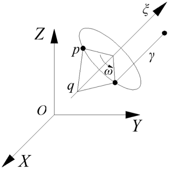
Spinor motion of rigid body.
In the formula,
According to formula (3), formula (4) can be expanded into the following form
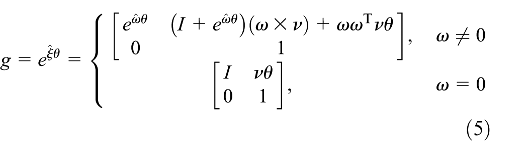
As described above, the index of the motion screw can represent the relative motion to the rigid body. In other words, after the spinor motion on the rigid body, and compared with the fixed S, T converts its instantaneous position and orientation to the following form

In the formula,
Exponential product equation
For open-chain robots with freedom degrees of n, the position and orientation of the end effector are made up of combined motion of the joints. When a set of joint angles is given, it is desirable to define the configuration of T, the end-effector coordinate system relative to S, and the base coordinate system. For the

For motion joints, the coordinate representation of the motion screw is
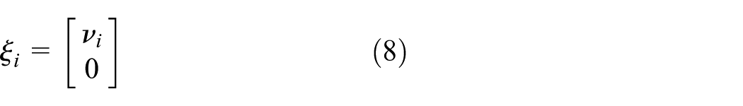
In the formula,
Combining the joint motions, the exponential product equation of the forward kinematics of the robot is obtained

In the formula,
Structural analysis of robot for hybrid high-altitude board installation
Figure 2 shows a 3D model of the robot for hybrid high-altitude board installation. The robot mainly composes of a base, a rotating frame, a greater arm parallelogram mechanism, an end posture adjusting device, an end effector, and a smaller arm parallelogram mechanism. We can find sequential connection among the base, rotating frame, the greater arm and smaller arm parallelogram mechanism, the end posture adjusting device, and the end effector. The robot features an end posture adjusting device. The equipment is compromised of an electric push rod assembly, a pitch fixing bracket, a six-axis motor-rotate vector (RV) reducer assembly, a four-axis motor-RV reducer assembly, and a swinging fixed bracket. For the four-axis motor-RV reducer assembly, it is bolted to the swinging fixed bracket by its middle portion. The lower portion is connected to the upper end of the pitch fixing bracket. For the six-axis motor-RV, it fixes its left end to the right end of the pitch fixing bracket. The lower end of the pitch fixing bracket and the six-axis motor-RV reducer assembly are, respectively, connected to the electric push rod assembly through the pin shaft.

Robot for parametric 3D model of a hybrid high-altitude board installation.
The high-altitude board installation robot weighs about 400 kg and its load reaches about 80 kg. Compared with traditional cast robot, both the greater and the smaller arms of the robot are welded by hollowed-out boards. The hollow shape can be triangular, round, elliptical, rectangular, and so on. They are chosen with assurance of the strength and rigidity of the robot itself. The shape of each board is processed by linear cutting. It greatly reduces the cost of the single piece of the robot and its own weight. During the design stage, the robot endures 3D virtual design through 3D software. It is to ensure the overall appearance of the robot, to shorten designing time, and to reduce designing cost. In addition, it helps to reduce robot weight by using finite element analysis software to analyze the overall performance of the robot. It further improves its working ability. Because of higher rigidity and lightened weight using hollow board welding, the robot overcomes the influence of strong wind and vibration in high-altitude environment. It meets the work requirements of low weight, high rigidity, and low wind resistance in high altitude. With this robot, we can improve the production efficiency significantly by means of pure automatic installation of the building board. The operator can also complete auxiliary installation of the board by manipulating the six-dimensional force sensor mounted on the robot. In the construction process, only one operator is required to assist the robot to install boards. It reduces labor intensity and enhances construction safety.
Robot forward kinematics analysis
Analysis method of kinematics of hybrid robot based on the screw theory
Since the hybrid robot is usually obtained by expanding the series structure on the parallel robot motion table, a main motion chain can always be found from the hybrid robot. This main motion chain can be regarded as a series robot in the main kinematic chain. Some of the components are subordinate to the parallel robot. Therefore, the hybrid robot can be regarded as a series robot. It drives the joint motion by using the parallel robot. In light of this feature of the hybrid robot, the method of kinematics analysis of the series and parallel robots is carried out with reference to the screw theory. And then we propose a construction method of kinematics equation of the hybrid robot. It is based on the screw theory. First, the main kinematic chain and the sub-chain of the hybrid robot should be defined to construct the structural equations of two kinematic chains. Second, the equation should be simplified to obtain the pose mapping relationship. The relationship is between the passive joints in the main kinematic chain and the active joints in the auxiliary kinematic chains. Third, the exponential product formula should be applied to analyze the main kinematic chain. In addition, the mapping relationship is gained between the joints of the active chain and the end effector. With all these finished, the mapping relationship will include the passive joint parameters. Finally, when only the parameters of the active joint are contained, the two mapping relations obtained above should be considered, and then the pose mapping relationship of the robot active joint and the end effector is obtained. Then, the motion analysis of the hybrid robot is completed.
To determine the mapping relationship between the main kinematic chain joints and the end effector
Figure 3 is a schematic diagram of the robot structure and a reference configuration. In this figure, there are two main components. The greater arm parallelogram mechanism

Structure diagram and reference configuration of robot.
The board installing robot shown in Figure 3 has a reference configuration when

By arranging equation (10), we get

The instantaneous movement of the rigid body can also be seen as a momentary rotation around an axis at infinity. In this way, the instantaneous rotation and instantaneous movement of the rigid body can be combined. As shown in Figure 4, if rigid body 2 has relative rotation and movement with respect to rigid body 1, the rigid body rotates


Schematic diagram of workpiece motion screw.
Here, the lower corner symbol i indicates the absolute instantaneous motion of the synthesis. The original and the dual part are respectively


Therefore, equation (10) can be organized as

of which
From equation (8), the motion screw coordinate of the horizontal slider of the robot can be solved. From equation (7), the motion screw coordinates of the remaining joints can be obtained. It can be seen from Figure 3 that the unit vector of each joint axis is

According to the structural parameters of the robot, the points on each joint of main chain are taken as
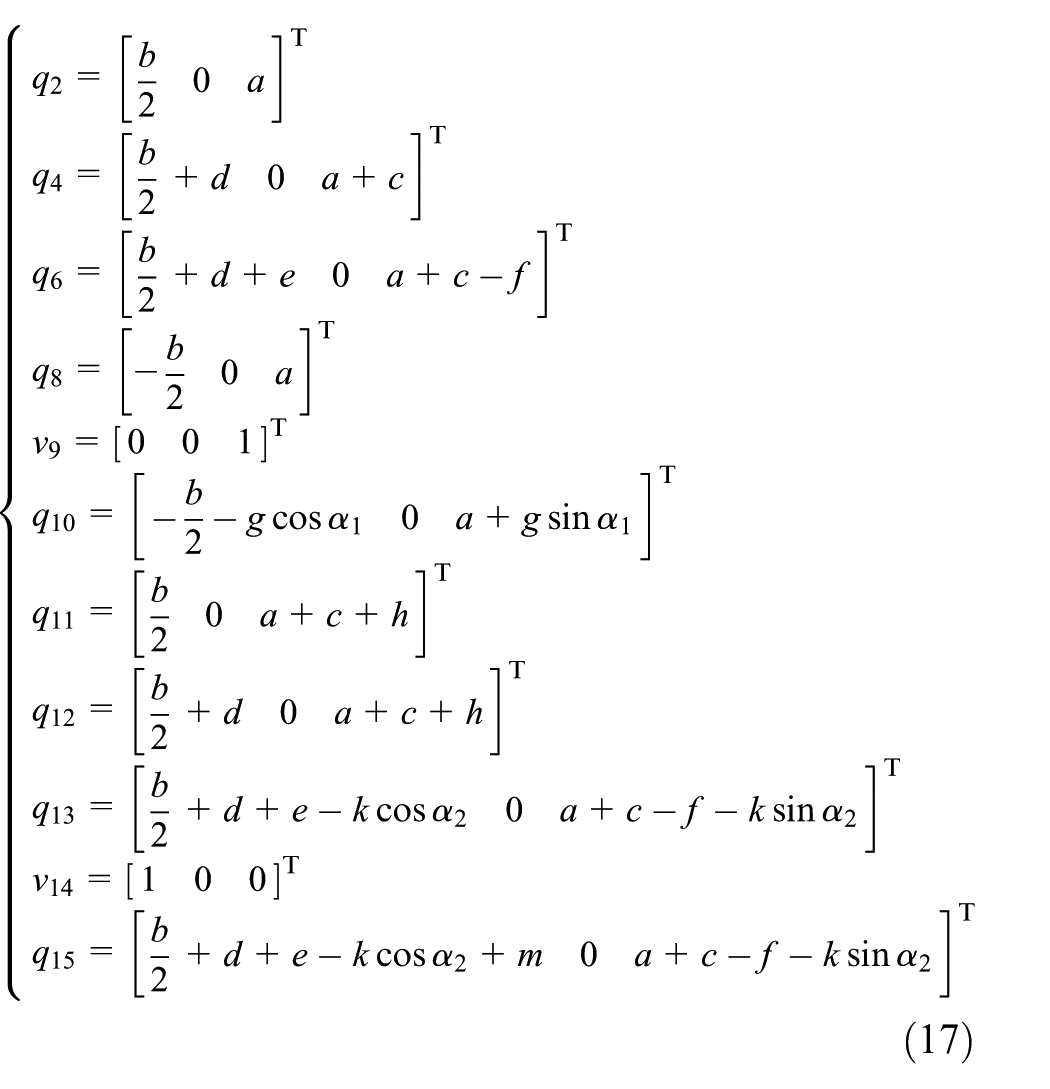
In the above equation, b is the distance between

In the previous analysis of the structure of the high-altitude board installation robot, it can be seen that it is the active part of the parallel structure in the arm. It rotates in figure
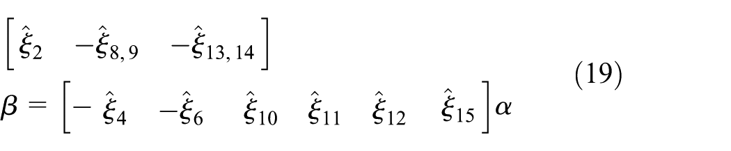
When the position


In the above equation,
To establish the kinematics forward equation of the main chain
When

In the above equation, P0 is the distance (mm) between the support base and the end of the robot operation in the S coordinate system of Figure 3; the rest are in the same way.
From Figure 3, the unit vector of each joint axis that has not been solved in the active chain is

According to the structural parameters of the robot, the joints on each screw axis are taken as

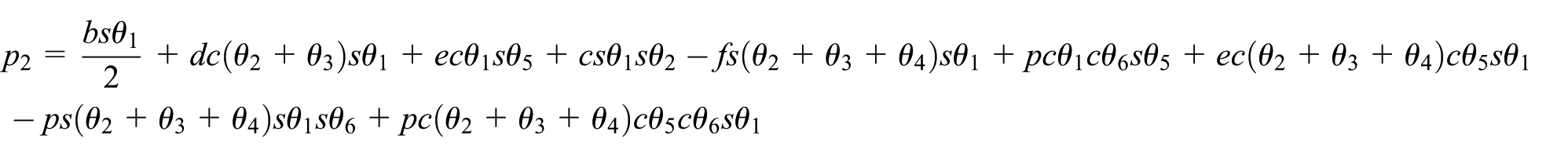
From equation (9), we can gain that the positive kinematics equation of the main kinematic chain is

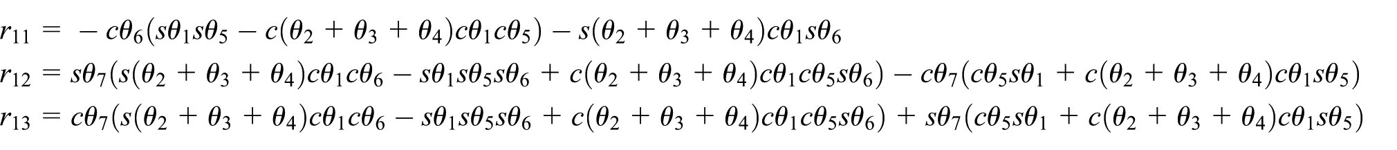
It can be developed as

In the equation,


of which
Forward kinematics equation of robotic active chain
The robot forward kinematics equation should only contain active joint parameters.

In the formula
Simulation and kinematics test
Kinematics simulation
The premise of whether the robot can meet the job requirements is to work out the workspace. In terms of ergonomics, it is most labor-saving for workers to carry out board installation and construction within a working height between 1000 and 1500 mm. For this reason, the robot’s working space moves in the vertical direction from 930 to 1550 mm. Because the distance between the high-altitude platform and the building is 300 mm, to ensure that the robot can grab the board and install it on the wall, the robot has a movement of at least 350 mm forward or backward. For the purpose of installing multiple boards at the same height, the width of the high-altitude board is mostly about 1000 mm. It adds the adjustment amount when the board is installed. It amounts to a motion range of 1430 mm for the robot in the left-right direction. The working space is

According to equation (29), the rationality of the robot is based on kinematics equation (27). Using the numerical calculation function and data visualization function in MATLAB, the workspace of the robot can be solved efficiently and quickly.
23
The working range of the robot is drawn according to equation (27) of the robot kinematics. This is shown in Figure 5(a). The working range
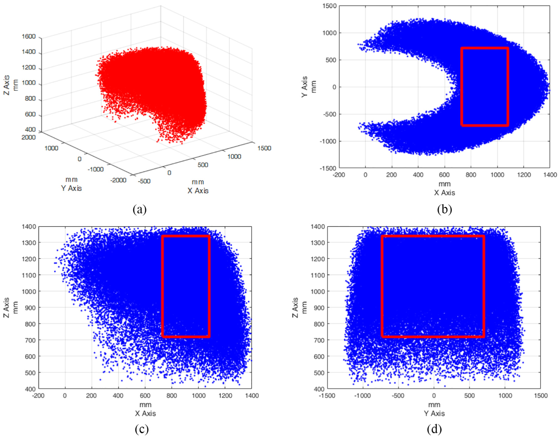
The cloud image of the workspace: (a) three-dimensional cloud image, (b) two-dimensional (X-Y) cloud image and requirement workspace block diagram, (c) two-dimensional (X-Z) cloud image and requirement workspace block diagram and (d) two-dimensional (Y-Z) cloud image and requirement workspace block diagram.
Kinematics test
In order to verify the correctness of the kinematics equation above, the kinematics test is carried out using the platform of the high-altitude board installation robot.
22
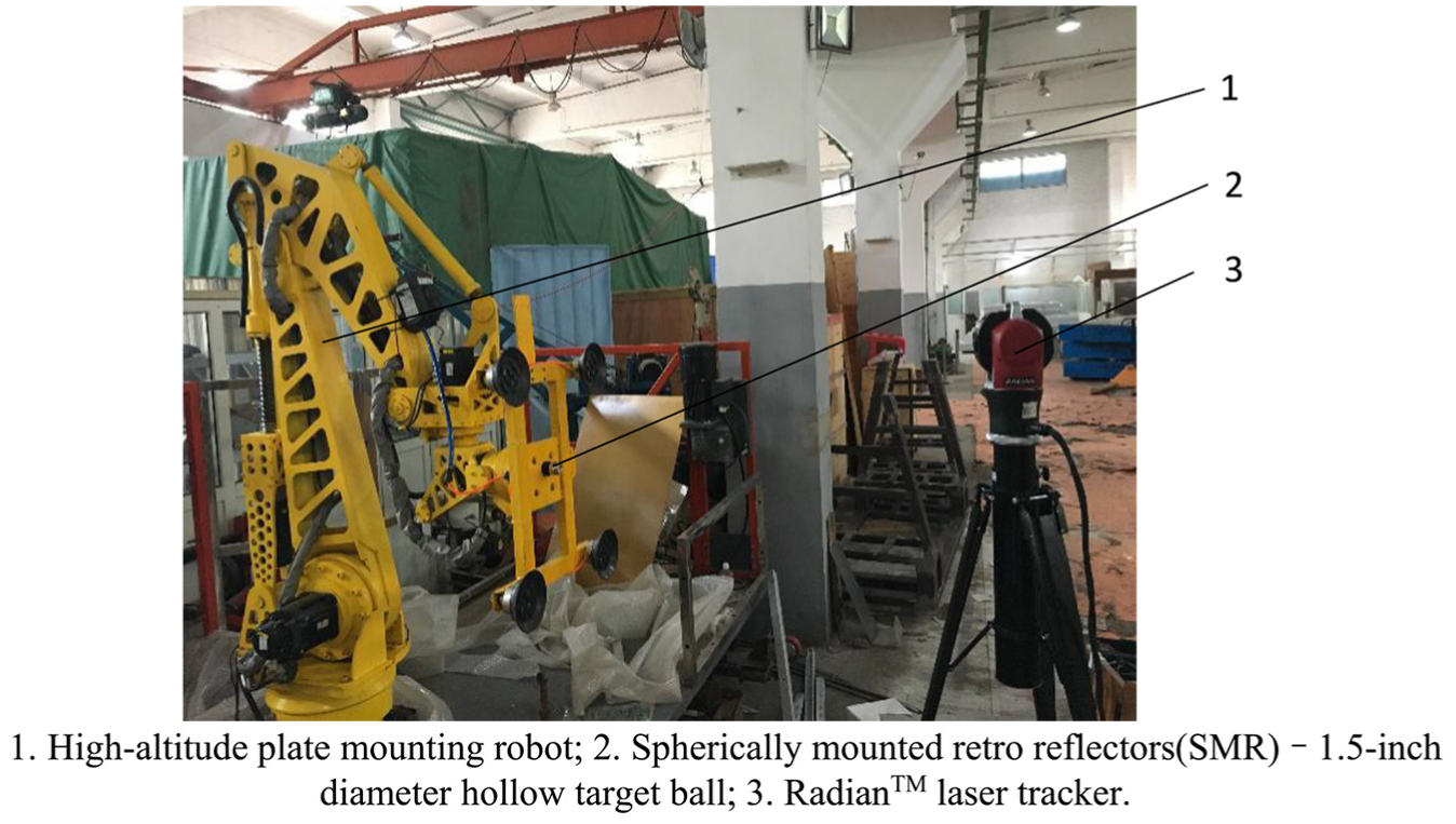
Figure 6 shows the kinematics test platform. On the left side of the figure is a high-altitude board installation robot. A spherically mounted retro reflector (SMR)—1.5-inch diameter hollow target—stands in the middle. A RadianTM laser tracker is on the right of Figure 6. The board installation robot moves with respect to axis Z of the coordinate system S. It is based on the central axis of the rotating base. The bottom surface of the rotating base of the robot is the plane XOY. It is assumed that the position coordinate of the board installation robot in the basic coordinate system S is
Kinematics experimental platform.
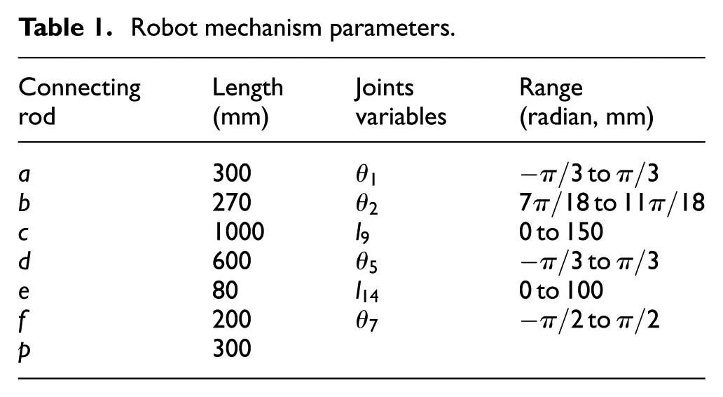
Assume that
Robot mechanism parameters.
According to the test results, the position error of the robot end effector shown in Table 2 can be obtained on the axes X, Y, and Z. It can be seen from Table 2 that the large absolute position error is 0.5 mm for the end effector on the X, Y, and Z axes. It can be reduced by improving the geometrical parameters of the robot and the accuracy of joint servo positioning. The high-altitude board installation robot proposed in this article takes boards as target object for clamping and installation. Its positioning accuracy of 0.5 mm for the end effector meets the national standard of 1 mm of the board gap. It also satisfies the operation requirements of clamping and installing boards for the robot end effector. In addition, it proves to be feasible and correct for the method proposed in this article to analyze the kinematics of the hybrid robot which is based on the screw theory.
End-effector position error.

Conclusion
According to the process characteristics of board installation, a new type of hybrid robot was constructed by combining the characteristics of parallel robot and series robot. It can help increase the rigidity of the whole robot arm and obtain a larger working stroke of end effector through a smaller drive stroke. In this way, we can satisfy the performance requirements of board installation work for the structural strength of the robot and the large workspace of the end effector.
This method of constructing the kinematics equation of a hybrid robot is based on the screw theory. It first decomposes the kinematic chain of the hybrid robot. Then, it converts the discussion point from the forward kinematics of the hybrid robot into single open-chain robots and the mapping relationship between passive joints in a single open-chain and active joints of the robot. Also, mathematical tools such as exponential product formula and structural equation are used to solve the sub-issues mentioned above. Finally, we have discussed all the results of those sub-issues and gained the kinematics positive equation of the hybrid robot.
In this article, the structural analysis of the hybrid board installation robot is carried out. The forward equation of the kinematics of the robot is established using the proposed kinematics analysis method. Then, the equation and MATLAB help obtain the cloud map of the robot workspace. It verifies that the robot workspace fully meets the work requirements. With that equation and analysis of the robot kinematics test platform, the absolute error of the end tool coordinate system is 0.5 mm between the theoretical value and the actual value. It meets the national standard of the board gap. Therefore, the method proposed in this article is proven to be feasible and correct for constructing the kinematics equation of the hybrid robot for board installation.
Footnotes
Handling Editor: James Baldwin
Declaration of conflicting interests
The author(s) declared no potential conflicts of interest with respect to the research, authorship, and/or publication of this article.
Funding
The author(s) received no financial support for the research, authorship, and/or publication of this article.