
Abstract
To overcome the drawbacks of using a traditional proportional-integral-derivative (PID) control method for a robot driver system, such as requiring preliminary offline learning, big overshoot and large speed fluctuation, a new method for speed tracking of a robot driver system based on sliding mode control is proposed in this paper. Firstly, the coordinated control model of multiple manipulators for the robot driver is built, which achieved coordinated control of the throttle mechanical leg, clutch mechanical leg, brake mechanical leg and shift mechanical arm for the robot driver. On the basis of this, a speed tracking sliding mode controller for a vehicle robot driver is designed using the method of multiple sliding surfaces design, and the variable structure control laws of throttle and brake are designed respectively, which realize the speed tracking of the given driving test cycle. Experimental results demonstrate that compared with the PID control method, the proposed method can obviously reduce the overshoot of vehicle speed tracking control and greatly improve the accuracy of vehicle speed tracking. The vehicle speed tracking accuracy stays within a tolerance band of ±2 km/h, which meets the requirements of national vehicle test standards. Furthermore, the action of the speed tracking control in the same driving test cycle using the proposed method is consistent, so that the robot driver has good repeatability. Therefore, it can ensure the effectiveness of the vehicle emission test.
1. Introduction
With the rapid increase of vehicle use, the amount of pollution entering the atmosphere generated by vehicle exhaust emission gas is increasing. Due to the increasingly strict laws of environmental protection, vehicle emission regulations have become more and more rigid. Consequently, the automobile industry has been trying hard to decrease the quantity of exhaust gas emissions and improve fuel economy [1]. A conventional way to measure the level of vehicle emission is usually made by a skilled human driver following a prescribed driving test cycle. However, the variable nature of human driver's behaviour greatly influences emission test results. A robot driver is a kind of special robot that can automatically drive under dangerous conditions and harsh environments. Instead of a human driver, it can be installed in the cab without the need for modifications and it can be adapted to different types of vehicles. The key technologies of vehicle robot driver are still secret in developed countries and only a few developed countries possessed the technology [2-5]. There is the DNC-1 and DNC-2 type robot driver developed by Southeast University and Nanjing Automobile Research Institute in China with independent intellectual property rights [6-9]. Compared with the human drivers, a vehicle robot driver has advantages of reducing test time, cost and improving test accuracy. It can free human drivers from uncomfortable and tedious working conditions, provide more reliable and repeatable test results than that of a human driver, and markedly quicken the research and development procedure of new vehicle types.
A vehicle robot driver must complete a specified driving cycle, in order to realize the tracking of the prescribed target vehicle speed, which is one of the key technologies. Kai Muller, et al. applied H∞ control to speed tracking, which can effectively inhibit uncertain external disturbances and the uncertainty of vehicle parameters. However, the adjustment of control parameters is very complex [10]. Chen Xiaobing, et al. utilized variable parameter PID control to realize the speed tracking of a robot driver. However, its control parameters have the difficulty of tuning and speed fluctuation [11]. Oscar Castillo, Ricardo Martinez-Marroquin, et al. described the application of Ant Colony Optimization (ACO) and Particle Swarm Optimization (PSO) on the optimization of the membership functions' parameters of a fuzzy logic controller (FLC) in order to find the optimal intelligent controller for an autonomous wheeled mobile robot [12]. Abraham Melendez, Oscar Castillo, et al. described the reactive and tracking control of a mobile robot using integration methods to combine the response of both types of controls based on fuzzy logic [13]. Ricardo Martínez-Soto, Oscar Castillo, et al. designed a Takagi-Sugeno fuzzy logic controller to force the real velocities of the autonomous mobile robot and to satisfy the control objective. With regard to the parameters of the membership functions, the minimal and the maximum values in the search range for the genetic algorithm are used to find the best fuzzy controller system [14].
Sliding Mode Control (SMC) is achieved through switching the controller structure, including control law or control parameters, according to the degree of deviation from system status to the sliding mode, so that the system runs in accordance with the law provided by the sliding mode, which has been widely used in robot control, vehicle control and other areas [15-19]. Because its sliding mode has the invariance of system parameter changes and external disturbances, and the control algorithm is more robust and relatively simple, in this paper sliding mode control is adapted to the speed tracking of the vehicle robot driver, which improves the accuracy of speed tracking and the repeatability of driving action for the robot driver.
2. Problem Statement
According to the requirements of antipollution devices for passengers cars prescribed in GB 18352.3–2005 “light-duty vehicle emission limits and measurement methods (China III and IV stage)” that is a specified type-V driving cycle, new light vehicles must perform an emission durability test for 80000 km [20]. A speed table of durability test consist of 11 cycles and the mileage of each cycle is 6 km. During the previous nine cycles, the vehicle should park four times in each cycle and the engine should be idle for 15 seconds each time. The relationship between distance and speed in the former nine cycles is shown in Fig. 1.
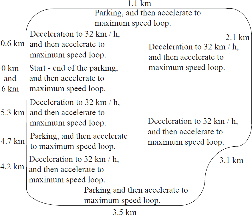
Driving standard of vehicle emission durability test
In the tenth cycle, the vehicle should run at a speed of 89 km/h. In the eleventh cycle, the vehicle accelerates up to 113 km/h from begin stationary to the maximum acceleration, braking should be used to make the vehicle park at half way through the cycle mileage, that is 3 km, then the vehicle should be idle for 15 seconds, and finally the vehicle accelerates again at the maximum acceleration. The second and sixth maximum cycle speed are 48 km/h. The fifth, seventh and ninth are 56 km/h. The first, third and fourth are 64 km/h. The eighth is 72 km/h. The tenth is 89 km/h. The eleventh is 113 km/h. The robot driver can automatically drive without the need for modification to the vehicle instead of a human driver, and it manipulates the vehicle according to the requirements of the pre-set driving cycle, namely time-speed curves and achieves the coordinated control of the throttle pedal, clutch pedal, brake pedal and shift lever.
3. The Control Method
3.1 System Configuration
The vehicle robot driver primarily consists of the following components: mechanical unit that included actuators for throttle mechanical leg, brake mechanical leg, clutch mechanical leg and shift mechanical arm; sensors for position, force, vehicle speed and engine speed; motor drive control unit. The robot driver adopts servo motor drive. The operation of the robot driver is flexible and rapid like the human driver, which meets the movement requirements of rapidity for the shift and brake, slow motion for the throttle and rapidity combined with slow motion for the clutch. Fig. 2 shows the system configuration of the robot driver.

System configuration of the vehicle robot driver
Among them, the throttle mechanical leg is driven by an AC servo motor, in order to achieve high-precision positioning of the throttle. The brake mechanical leg is driven by an AC servo motor, in order to achieve the deceleration control through the self-adjustment of the braking force. The clutch mechanical leg is driven by an AC servo motor, in order to adjust the speed, which meets the requirements of clutch movement during the process of startup and shift. The shift mechanical arm is the key component of the vehicle robot driver, which adopts a seven-link two-DOF closed-chain mechanism – its internal structure is shown in Fig. 3.
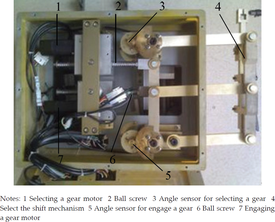
Internal structure of the shift mechanical arm for the vehicle robot driver
The seven-link two-DOF closed-chain shift mechanical arm is composed of a shift linkage mechanism, an angle detection unit and a motion control unit. Among them, the shift linkage mechanism can be simplified as shown in Fig. 4, where P is the fixed point of the shift lever. The lever DO2 is whirled around O2 through the ball screw driven by selecting a gear servo motor, whose rotation angle is θ21. The lever EO3 is whirled around O3 through the ball screw driven by engaging a gear servo motor, whose rotation angle is θ31. The trajectory of P relates to θ21, θ21 and the length of each linkage. The angle coordinates of the shift mechanical arm are measured by the angle sensors for selecting a gear and engaging a gear, and the spatial coordinates are determined by the angle coordinates. With the premise of no need to change the vehicle shift mechanism, mechanical decoupling between both selecting a gear and engaging a gear is achieved, and the precise control for the shift mechanical arm of the robot driver is ultimately achieved. The Yaskawa AC servo motor made in Japan is used in the all drive system for the robot driver actuators, whose type is SGMAH02A, namely, rated power 200 W, rated speed 3000 r/min, maximum speed 5000 r/min, rated torque 0.637 N•m and instantaneous torque 1.91 N•m.

Diagram of the shift mechanical arm linkage
To achieve the decoupling between selecting a gear motion control and engaging a gear motion control, at the time of picking a gear and engaging a gear, the engaging gear motor is only manipulated and the selecting gear motor remains stationary. Conversely, at the time of selecting a gear, the selecting gear motor is only manipulated and the engaging gear motor remains stationary.
3.2 The Control Model
A series of information consisting of speed v[i], time t[i] and gear g[i] is stored in the speed and driving commands table of the robot driver, where i = 1,2,…,n. The robot driver determines operating conditions that is Mode[i] according to the information of v[i] and g[i], and then executes the corresponding ignition, starting, shift and acceleration in accordance with Mode[i]. According to the characteristics of V-test driving cycle, the robot driver is able to judge the condition that is acceleration (v[i] < v[i +1]), steady speed (v[i] = v[i +1]) or deceleration (v[i]> v[i+1]) in accordance with the value of the pre-set former target speed v[i] and current speed v[i + 1], then respectively enters throttle or brake control module. The speed and driving commands table of 48 km/h driving cycle for the robot driver is shown in Table 1. The shift condition is obtained from command table g[i], acceleration
Speed and driving commands table of 48 km/h driving cycle for the robot driver

Note: In the row of “Gear”, “8” stand for neutral gear; “10” stand for disengaged, shifting 1st gear; “11” stand for starting with 1st gear; “99” stand for end of test.
The coordinated control model of multiple manipulators for the robot driver is shown in Fig. 5. According to operational requirements, each manipulator motion closed-loop respectively constitutes braking force control closed-loop, clutch speed and position control closed-loop, throttle position control closed-loop and shift speed and position control closed-loop. In accordance with the set vehicle speed and control command tables, the robot driver achieves the coordinated control of the throttle mechanical leg, clutch mechanical leg, brake mechanical leg and shift mechanical arm and realizes the tracking of vehicle speed, whose control algorithm adopts the sliding control method.

Coordinated control model block diagram of multiple manipulators for the robot driver
3.3 Design of the Speed Tracking Sliding Mode Controller
The aim of speed tracking control for the robot driver is to design a throttle and brake control law so that the test vehicle speed can track any reasonable smooth trajectory, that is the driving test cycle. The controller must determine throttle and brake pedal trajectory which can make vehicle speed v track the desired vehicle speed vd. It does not belong to the field of standard sliding mode controller design, and thus the multiple sliding surface design method must be adopted. The controller design is divided into three steps.
(1) Definition of a sliding mode surface
Defining the sliding mode surface S1 =v – vd. Assuming that S = v–vd = –k1S1 and its expansion is as follows.
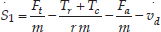
where m is the vehicle mass, r is the tire radius, Ft is the driving force, Tr is the rolling resistance torque, Tc is the road grade resistance torque, Fa is the aerodynamic drag force and Fa= Cav2, Ca is the aerodynamic drag force coefficient. Because without the application of the throttle and brake pedal at the same time, the throttle control and brake control are separately considered, that is the throttle control is necessary only when S1 < 0 and brake control is necessary only when S1 > 0.
Because the emission durability test is conducted by the robot driver on a chassis dynamometer, there is no need to consider for Fa and Tc in Equation (1). So

Equation 2 is not a standard sliding mode formula and the throttle opening degree angle α cannot be solved by it. Therefore, some transforms must be made and the intermediate link must be introduced, that is done in order to obtain the expected front-wheel angular velocity.
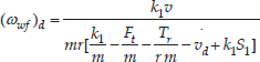
If ωωf is directly controlled to track the (
The desired turbine torque of torque converter is
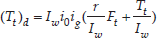
The desired turbine angular velocity of torque converter is

where Iw is the wheel moment inertia, i0 is the axle ratio, ig is the gear ratio. If the turbine torque Tt and turbine rotational speed of torque converter ωt can correctly track the trajectory shown in Equation (4) and (5), then in the limited period of time S1 = 0.
With the ratio ξ is the angular velocity of turbine and pump (ξ = ωt /ωp), and the engine angular velocity (ωe = ωp), the functional dependencies of the turbine and the pump torques are given by


where μ is the torque gain from torque converter input to torque converter output. Combining Equations (4), (5), (6) and (7), the desired value of ωe and Tp, that is (ωe)d and (Tp) d , can be obtained.
(2) The throttle control law
The control law of the throttle opening angle α is designed by (ωe)d and (Tp)d. Defining another sliding mode surface S2= ωe–(ωe) d , after differential it is S2 = ωe – (ωe)d = –k2S2.
Due to Ie ωe= Ti–Tr–Tf–Tp, yielding:

where Ie is the effective inertia of engine and torque converter pump parts, Tr is the rolling resistance torque, Tf is the engine friction torque Tf = 0.1056ωe +15.1, Tp is the torque converter pump torques. Assuming that the delay time is zero, the engine torque is [15,16]
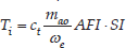
where the normalized air fuel influence, AFI, is a function of air-to-fuel ratio, and the empirical formula may be used: AFI = cos(7.3834·(A/F–13.5)). The normalized spark influence, SI, is a function of spark advance/retard from MBT (minimum-spark-advance for best torque), and the empirical formula may be used: SI = (cos(SA–MBT))2.875, where SA is the spark advance/retard from TDC (Top Dead Centre). The capacity factor of torque converter, ct, represents the maximum torque capacity of an engine for a given air mass and engine speed. Yielding:

where

The state equation for the mass of air in the engine intake manifold m is given by continuity.

where the mass of air flowing out of the intake manifold and into the cylinders, mao, is determined from tables provided by the manufacturer. The mass of air flowing into the intake manifold is

where MAX represents the flow rate at full throttle, α is the throttle angle, TC is the empirical throttle characteristic, and PRI is a pressure influence function for compressible flow,

Inverting the desired value of the throttle characteristic TC(α) d yields the value of the control, α.
(3) The brake control law
When S1 > 0 the vehicle needs to brake, and when α = 0 the engine can also provide some brake force. When the throttle angle α and the brake angle αb are both zero, the vehicle deceleration is up to 0.5m/s2 through engine braking. Consequently, the brake control law is as follows:

4. Experimental Results and Discussions
4.1 Experiment
To verify the effectiveness of the proposed sliding mode control method for speed tracking of the robot driver, according to the national pollution emissions standards for passenger cars issued by the Environmental Protection Administration [20], a vehicle emission durability test is performed at the Nation Quality Supervision and Inspection Centre for Passenger Cars of China by skilled human drivers and the robot driver. The speed tracking accuracy of the standards is ±2 km/h.
The type of test vehicle is a Ford FOCUS 2.0, whose engine volume is 2.0 L. The type of chassis dynamometer is Burke 4100. The vehicle emissions durability test system consists of the chassis dynamometer simulating the driving road and the robot driver conducting the automatic driving instead of a human driver. The chassis dynamometer is equipped with power absorption and inertia flywheel, which simulates a variety of resistances which the vehicle undergoes during the process of driving on a straight road, including air resistance, rolling resistance, acceleration resistance, etc., thus making the test environment consistent with the road environment for a vehicle as far as possible.
The vehicle robot driver can be installed in the cab non-destructively, without any need for modifications to the vehicle. After conducting the self-learning of the vehicle geometric dimensions and vehicle performance parameters, the robot driver can automatically drive different types of vehicles. During the test process, the driving speed and driving instructions commands of the test cycle are firstly defined, after that, the test is conducted respectively by the robot driver and the skilled human driver. The robot driver fixed into the test vehicle and the vehicle durability test using the robot driver are shown in Fig. 6.
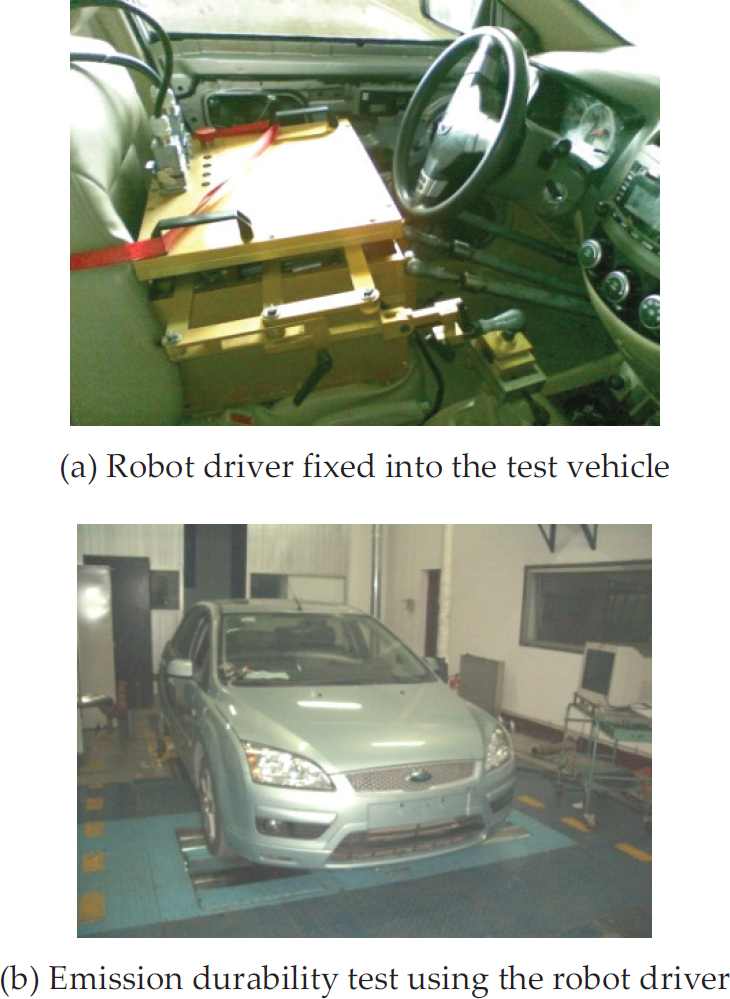
Robot driver fixed into the test vehicle and the emission durability test using the robot driver
4.2 Results and Discussions
The standard speed tracking curve of the emission durability test 72 km/h cycle is shown in Fig. 7. The results of speed tracking the test vehicle manipulated by the skilled human driver are shown in Fig. 8.

The standard speed tracking curve of the emission durability test 72 km/h cycle

The results of speed tracking with the test vehicle manipulated by the skilled human driver
As can be seen from Fig. 8, the human driver does not complete the test in accordance with the national vehicle test standards in the required time. Speed fluctuation is very large in the process of steady speed. The speed begins to fall when it doesn't reach the cycle speed during the first acceleration process of the first small cycle, and the speed doesn't go up immediately when it falls to cycle speed during the first and second deceleration process of the second small cycle, which does not meet national standards. As can also be seen from Fig. 8, the results of speed tracking with the test vehicle manipulated by the skilled human driver have poor repeatability, as the human driver is easily affected by experience, environment and other factors.
The results of speed tracking and partial comparison curves, where the test vehicle was manipulated by the robot driver respectively using PID control method and the proposed control method, are shown in Fig. 9 and Fig. 10.
Fig. 9(a) and Fig. 10(a) demonstrate that the speed tracking results using PID control have a large overshoot that is up to 5 km/h during the period from the acceleration process into the steady speed process. During the process of steady speed there is large vehicle speed fluctuation, which exceeds the requirements of national vehicle test standards.

The results of speed tracking the test vehicle manipulated by the robot driver

The partial comparison curves of speed tracking the test vehicle manipulated by the robot driver
Fig. 9(a) also shows that during the second acceleration process of the first small loop, the third acceleration process of the second small loop and the second acceleration process of the third small loop, the peak speed does not rise to the cycle speed required by national vehicle test standards. As can be seen from Fig. 9(b), the results of speed tracking the test vehicle manipulated by the robot driver using the proposed control method have good repeatability.
During the test, the vehicle speed is measured using a photoelectric sensor installed in the front drum of the chassis dynamometer. The coordinated control curves for the multiple manipulators of the robot driver using the proposed method are shown in Fig. 11.
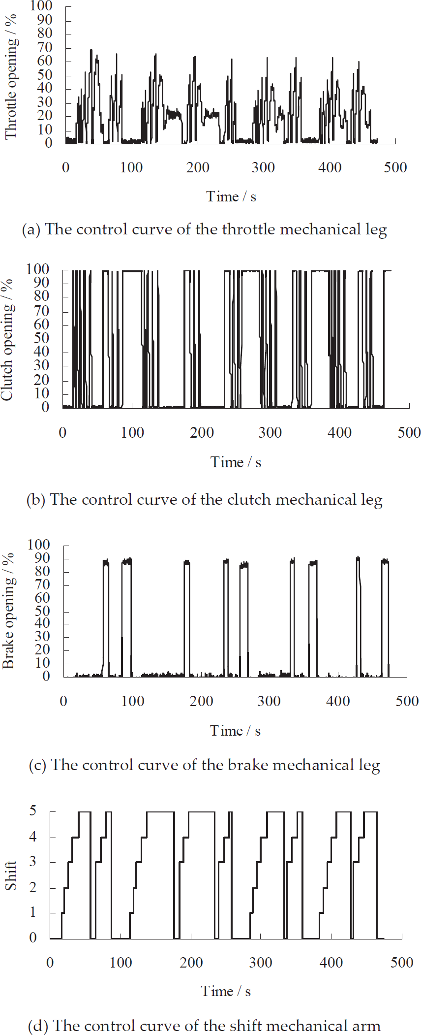
The coordinated control curves for the multiple manipulators of the robot driver using the proposed method
Throttle opening degree, brake opening degree and clutch opening degree are measured by potentiometer displacement sensors respectively installed in the throttle mechanical leg, brake mechanical leg and clutch mechanical leg. After the sensors output signals are calibrated, the corresponding throttle opening degree, brake opening degree and clutch opening degree are obtained. The throttle opening degree, brake opening degree and clutch opening degree are 0% when the throttle mechanical leg, brake mechanical leg and clutch mechanical leg are not pressed at all. They are 100% when they are pressed in the end. Meanwhile, the gear is measured by a potentiometer angle sensor installed in the shift mechanical arm.
As can be seen from Fig. 9(b), Fig. 10(b) and Fig. 11, the robot driver using the proposed control method can smoothly achieve starting, acceleration, shifting, steady speed and deceleration through the coordinated control of the throttle mechanical leg, brake mechanical leg, clutch mechanical leg and shift mechanical arm. The overshoot of speed tracking control during transition from the acceleration stage to steady stage is small. Moreover, the speed fluctuation at the steady stage is smooth, and speed control accuracy stays within a tolerance band of ±2 km/h, which meets the requirements of national test standards.
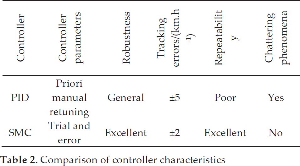
Additionally, the comparison of controller characteristics among the PID control and the proposed sliding mode control is made in Table 2. It shows that the proposed sliding mode control system is more suitable for the speed tracking control of the vehicle robot driver.
Comparison of controller characteristics
In addition to emission durability tests, the robot driver can also be applied to fuel economy tests, transmission losses and power transfer performance tests, high temperature and cold temperature environmental tests, vehicle noise tests automotive electromagnetic compatibility (EMC) tests, etc.
5. Conclusions
A novel approach to speed tracking control for a vehicle robot driver using multiple sliding surface control schemes is proposed in this paper, and a speed tracking sliding mode controller for a robot driver is designed. Moreover, theoretical analysis and experimental validation are made.
Experimental results shows that compared with the results of speed tracking the test vehicle manipulated by the skilled human driver and the robot driver using the PID control method, our robot driver using the proposed method can greatly improve the accuracy of vehicle speed tracking and repeatability, which meets the requirements of national vehicle test standards. The effectiveness and feasibility of the proposed theory and methods are verified by test results.
Footnotes
6. Acknowledgements
This research is partially supported by Project 51205208 supported by National Natural Science Foundation of China and China Postdoctoral Science Foundation funded project (grant no. 2011M500922)