
Abstract
To solve the shortcomings of existing control methods for an electromagnetic direct drive vehicle robot driver, including large speed tracking error and large mileage deviation, a new adaptive speed control method for the electromagnetic direct drive vehicle robot driver based on fuzzy logic is proposed in this paper. The electromagnetic direct drive vehicle robot driver adapts an electromagnetic linear motor as its drive mechanism. The control system structure is designed. The coordinated controller for multiple manipulators is presented. Moreover, an adaptive speed controller for the electromagnetic direct drive vehicle robot driver is proposed to achieve the accurate tracking of desired speed. Experiments are conducted using a Ford FOCUS car. Performances of the proposed method, proportional–integral–derivative, and fuzzy neural network are compared and analyzed. Experimental results demonstrate that the proposed control method can accurately track the target speed, and it can inhabit the change of speed caused by interference under different test conditions, and it has small mileage deviation, which can meet the requirements of national vehicle test standards.
Introduction
Vehicle robot driver is an intelligent industrial robot which can be equipped in a vehicle cab without any modification. It can be used for autonomous driving, replacing a human driver. Because the vehicle need not be modified, the vehicle robot driver can be directly installed in the different vehicle cab. Autonomous vehicles need to modify automobile structure, and the robotic system of it only limits constant vehicle. However, the electromagnetic direct drive vehicle robot driver (EDDVRD) has two outstanding advantages. First, it can achieve autonomous driving without the need of automobile modifications. Second, after a period of self-learning time, it cannot limit constant vehicle parameters, but manipulate any type of automobile. Its related technologies can be applied to emission durability test, vehicle performance test, vehicle noise test, high and low temperature environment test, vehicle road test, vehicle bench test and other fields.1–4
The driveway of the vehicle robot driver includes the hydraulic drive, the pneumatic drive and the servo electric drive. 2 The hydraulic drive is steady, but it needs an oil cylinder. 5 It is not easy for the pneumatic drive to accurate positioning and the real-time performance. 3 As a driving device of the vehicle robot driver, the servo electric drive needs a mechanism of rotary motion into linear motion.4,6 Electromagnetic linear motor can solve the shortcomings of three other drive styles. It can improve the transmission efficiency and transmission accuracy, and make the transmission mechanism simple.7–9 We adopt an electromagnetic linear motor as the drive device of the EDDVRD in this paper.
The EDDVRD must realize the tracking of given desired vehicle speed, which is one of the key technologies. The EDDVRD needs to complete the motion control for not only the robot itself but also the autonomous driving vehicle. Vehicle robot driver must coordinate throttle pedal, brake pedal, clutch pedal and shift level, so that it can achieve the tracking control of desired speed. There have already been considered various speed control approaches for robotic drivers. Chen et al. utilizes a variable parameter, proportional–integral–derivative (PID) control, to realize the speed tracking of vehicle robot driver. However, the test results show that it has some disadvantage, such as difficult tuning of control parameters, requiring preliminary offline learning, big overshoot, large speed fluctuation and bad adaptability. 10 Namik et al., 11 Nicholas et al., 6 and Chambers et al. 12 propose a PID controller, but the problems with pedal stick-slip, large nonlinearities and motor saturation limit the performance of the developed controllers. The results show that the maximum value of position is 0.4 mm, but the speed error is not a concrete value. It is more important that the vehicle model is shown to be a poor representation of the real vehicle; the main difference between the model and the actual system is the failure to predict the nonlinearity in the change from braking to throttle region, so that further testing is required.
Besides, during the process of automotive test, the road resistance is simulated on chassis dynamometer, which brings interference to speed control for the EDDVRD. The EDDVRD is a strongly nonlinear system. Fuzzy control does not require a precise mathematical model, and it can integrate the experience and knowledge of a human driver. It has a strong effect on resistance interference, so that it can ensure tracking control accuracy. 13 However, when fuzzy control is applied to robot control, it cannot meet the control targets of control plant, especially for the bottom control, so that fuzzy control needs another simple controller as a supplement.14,15 Fuzzy adaptive PID control has the advantages of both fuzzy control and PID control.
A new adaptive speed control method for an EDDVRD is proposed. The control system frame is presented. The coordinated controller for multiple manipulators is presented. Moreover, an adaptive speed controller for the EDDVRD is proposed to achieve the accurate tracking of desired speed. Experiments are conducted using a Ford FOCUS car. The performances of the proposed method, PID, and fuzzy neural network (FNN) are compared and analyzed. Experimental results demonstrate the effectiveness of the proposed method.
“Introduction” section provides the introduction. “Speed control method” section describes the adaptive speed control method. “Experimental results and analysis” section provides the experimental results and analysis. “Conclusion” section concludes the article.
Speed control method
Control system structure
The EDDVRD control system achieves the acquisition and processing of the signals, and realizes the control of mechanical actuators. The EDDVRD control system structure is shown in Figure 1 where TMS320F2812 DSP (Digital Signal Processor) chip is the core of the EDDVRD control system. The current position of the mechanical actuators, the displacement and current of the electromagnetic linear motor, vehicle speed and engine speed are transferred to the DSP. And then, according to the input data the test cycle condition pre-entered to memory, the actuator command signals are calculated. The EDDVRD adopts pulse width modulation (PWM) control and the displacement and the current double closed-loop control strategy. By means of changing the polarity and duty cycle of the PWM signal, the DSP controller changes the direction and magnitude of the electromagnetic linear motor current. The precise control of the EDDVRD is achieved by the saturation current. The control system for the EDDVRD realizes the measurement and diagnostics of the signal and the motion control of mechanical actuators, and it communicates with the teaching box. Besides, the teaching box is used to teach the vehicle structure parameters, such as the position of the throttle actuator, brake actuator, clutch actuator and shift actuator.
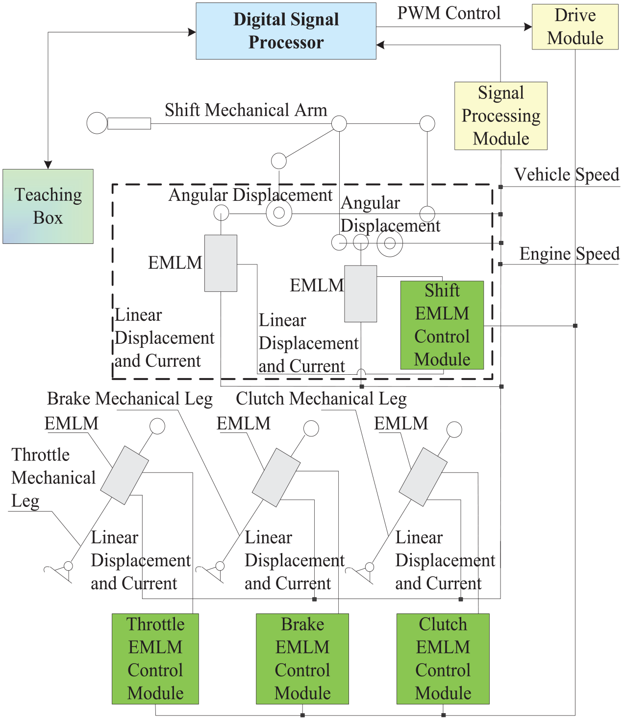
Control system structure of the EDDVRD.
The coordinated controller
The multiple manipulators coordinate the force, the speed, the displacement and the timing, so that the EDDVRD control system completes the motion control of robot itself and realizes the tracking of vehicle speed. The speed
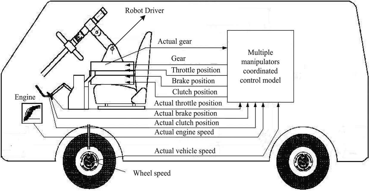
Relationship among the coordinated control model, the vehicle and the robot driver.
The vehicle speed and engine speed are controlled by simultaneously manipulating the throttle and clutch mechanical legs. During the shifting process, the coordinated control of throttle, clutch mechanical leg, and shift mechanical arm are achieved. The vehicle speed at every second is stored in the driving command table. The desired acceleration is calculated by the speed. The comparison between driving command table and throttle and brake look-up table is conducted. Due to the influence of sampling signal noise, sampling frequency and the deviation between the model values and actual values in the switching interface, the switch can make the control system futtering. Since the throttle and brake actuators cannot be activated simultaneously in a real driving process, frequent switching between them is not advantageous. In order to eliminate the buffering and improve the stability of the control system, a thin switching buffer layer (see Figure 3, shown in dashed lines) is introduced in the switch controller for throttle and brake mechanical leg. 1
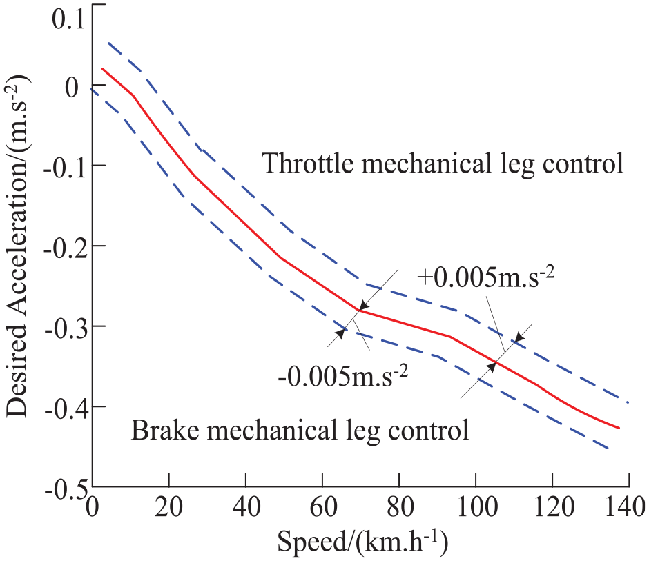
Switching laws of throttle and brake actuators.
Adaptive speed controller
The block diagram of adaptive speed controller for the EDDVRD is shown in Figure 4 where
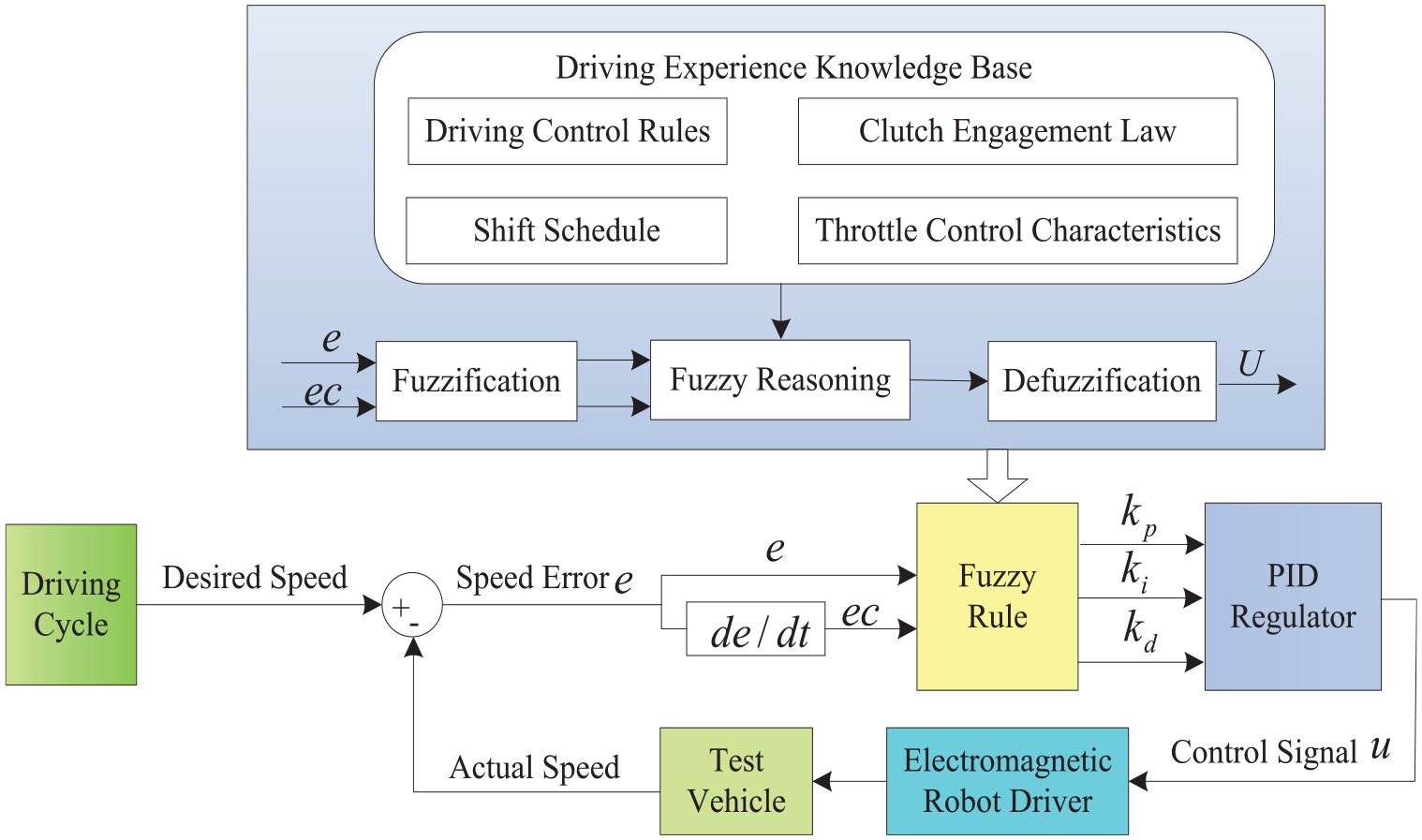
Block diagram of adaptive speed controller for EDDVRD.
According to the desired speed and the target speed,
The input and output variables of the controller are determined.
Define the speed error
2. The input variables of the controller are fuzzified; the membership function of the input and output variables is established.
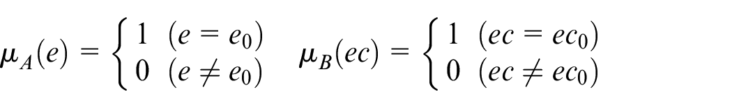
The fuzzy computing of input variables adopts a single point fuzzy set. If the system input is
Input and output curves of the EDDVRD fuzzy control system are shown in Figure 5. The membership functions of the input and output variables separately adapt trigonometric function, sigmoid function, Z-type function and the combination of Z-type function, trigonometric function and sigmoid function. It can be seen from Figure 5(a)–(c) that the input and output curves of the EDDVRD fuzzy control system whose membership function adapts trigonometric function, sigmoid function and Z-type function have a serious nonlinearity, which will result in bad control sensitivity and bad adaptability. It can be seen from Figure 5(d) that input and output curves of the EDDVRD fuzzy control system whose membership function adapts the combination of Z-type function, trigonometric function and sigmoid function are very smooth, which can improve the control sensitivity and adaptability. Therefore, the membership functions of the input and output variables all adapt the combination of Z-type function, trigonometric function and sigmoid function. The membership functions of the input and output variables are shown in Figure 6.
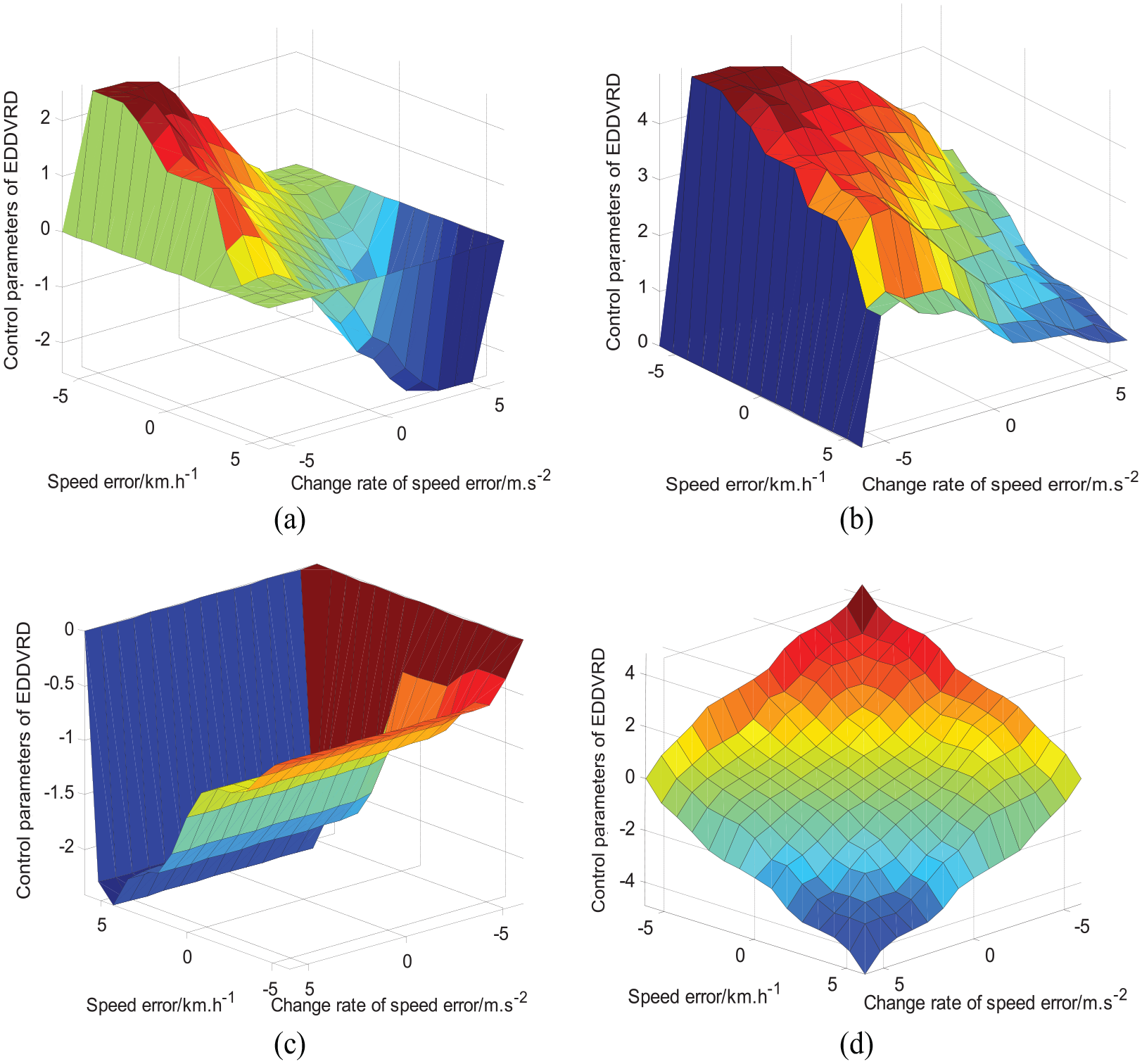
Input and output curves of EDDVRD fuzzy control system: (a) trigonometric membership function, (b) sigmoid membership function, (c) Z-type membership function and (d) combination membership functions.
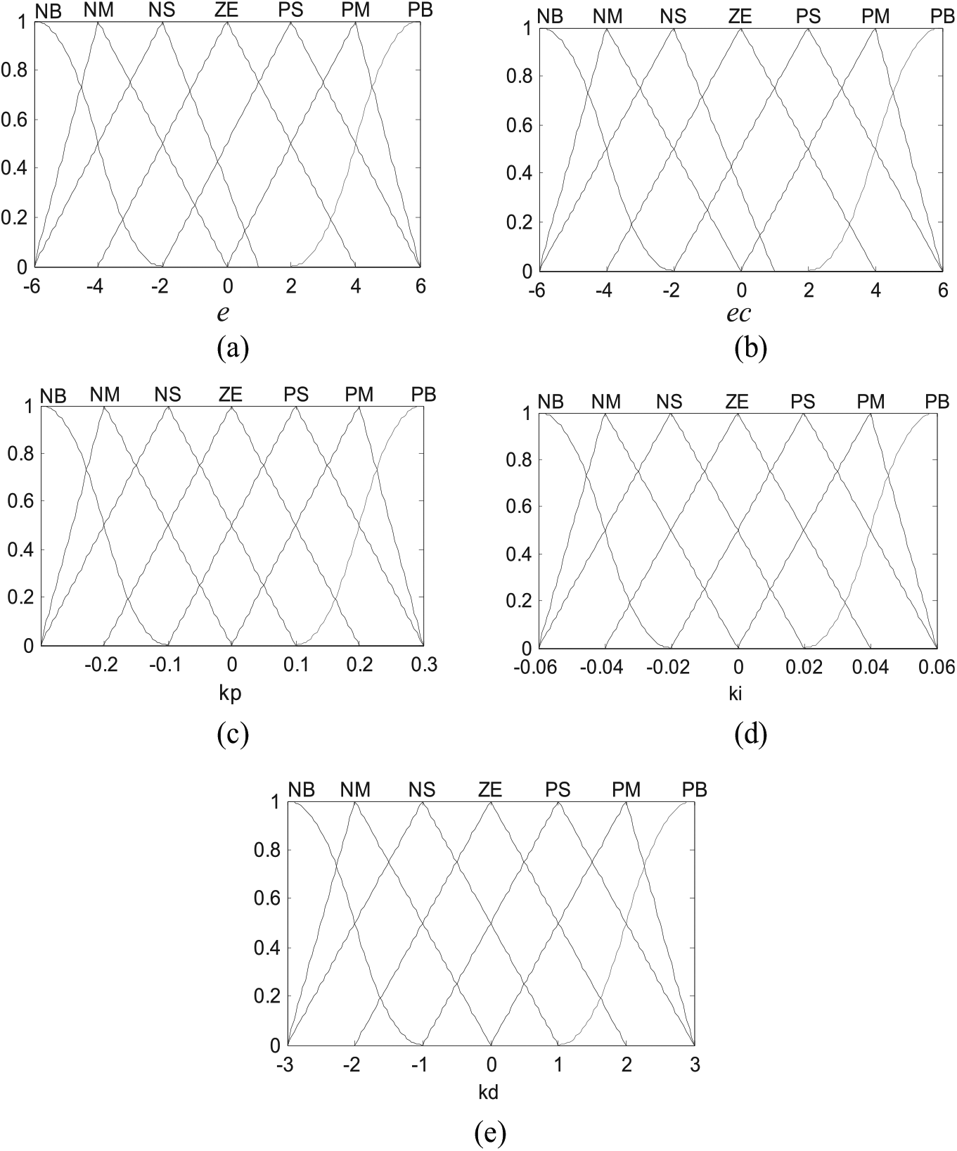
Membership functions of the input and output variables: (a) membership function of
3. The fuzzy control rules of the controller are established.
In the process of conducting fuzzy computing, “and” adapts intersection method, “also” adapts merger law, fuzzy synthetic adapts maximum–minimum method, fuzzy implication adapts intersection method and defuzzification adapts gravity method. The fuzzy control table of
Fuzzy control rules table of speed tracking.
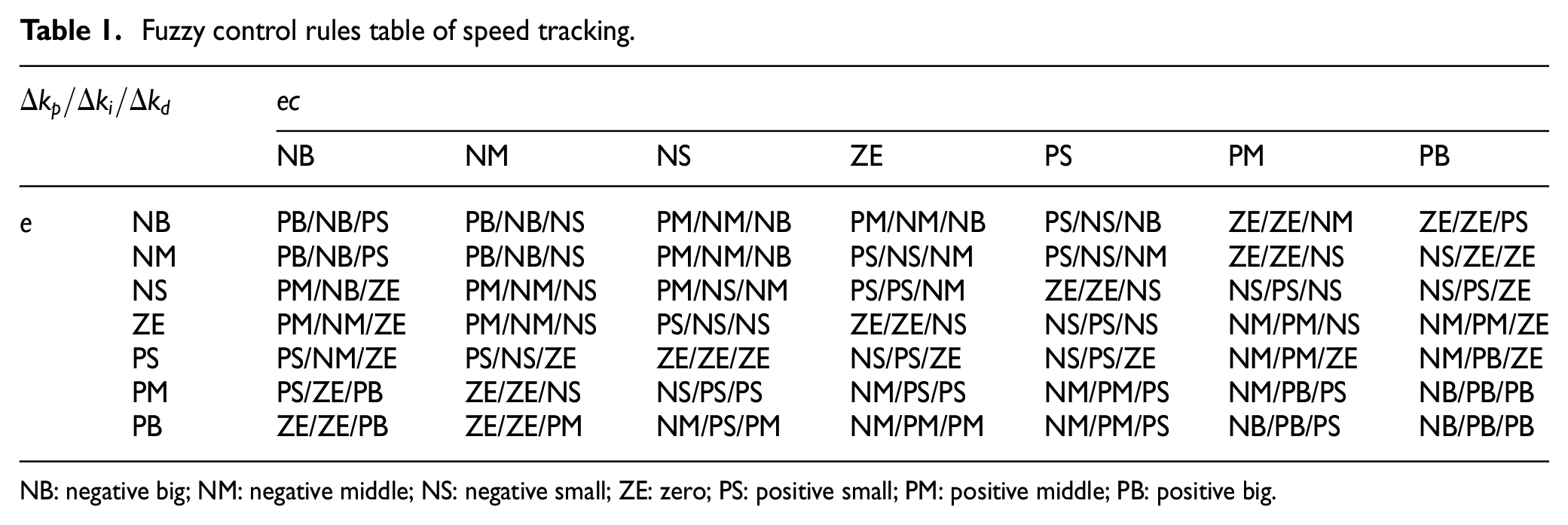
NB: negative big; NM: negative middle; NS: negative small; ZE: zero; PS: positive small; PM: positive middle; PB: positive big.
4. The online self-regulating of the controller is conducted.
Assuming
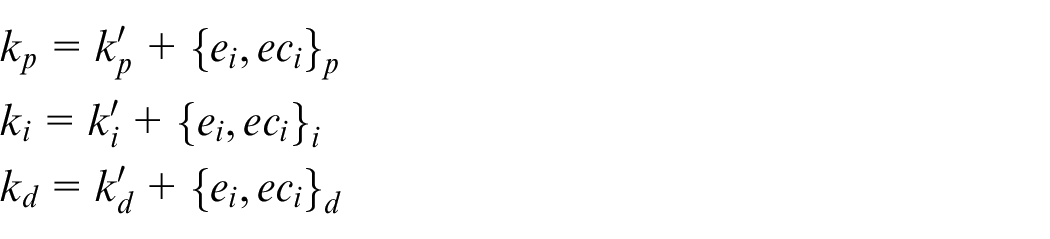
In the process of running online, the online self-regulating of PID parameters is completed by the fuzzy rules. The flow chart of the controller is shown in Figure 7. During the process of speed tracking control for the EDDVRD, the adaptive adjustment process curve of
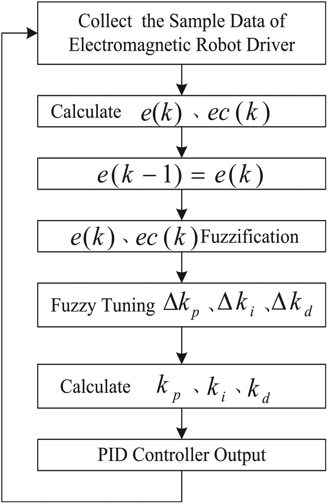
Flow chart of the speed controller for EDDVRD.
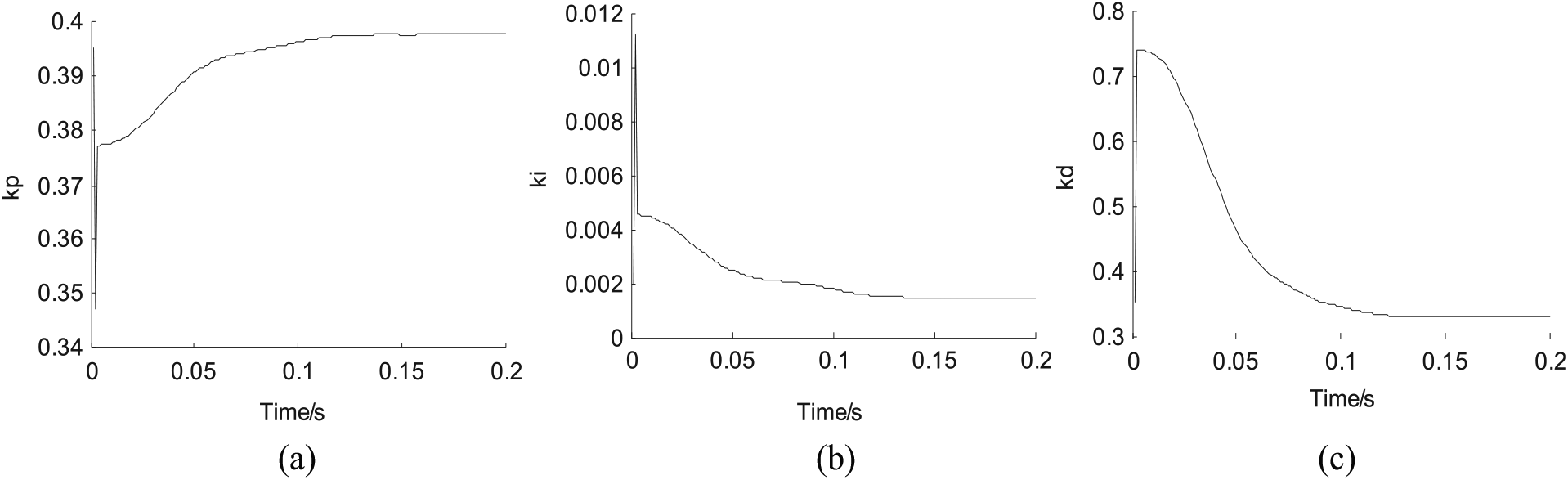
Adaptive adjustment process curve of the speed controller: (a) adaptive adjustment curve of
Experimental results and analysis
To verify the effectiveness of the proposed control method for the EDDVRD, in line with the required national standards of emissions durability, 16 the vehicle durability emission test is performed by the EDDVRD. The vehicle model is Ford FOCUS 2.0. The chassis dynamometer type is Burke 4100. The EDDVRD installed in a cab of test vehicle is seen in Figure 9. After conducting a vehicle structure and dynamic performance self-learning method, the EDDVRD can automatically manipulate different vehicle types. 1
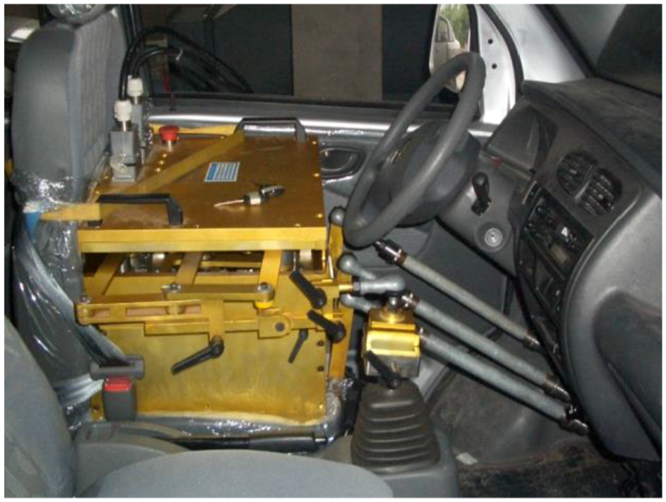
The EDDVRD installed in a test vehicle.
The test results of speed tracking control, comparison of speed tracking control and speed tracking control error comparison are shown in Figures 10–12, where the test vehicle is manipulated by the EDDVRD, respectively, using PID control method, FNN control method and the proposed control method. The parameters of PID control and FNN control are defined in Chen et al. 17 It can be seen from Figures 10–12 that the speed tracking results using PID control have a very large overshoot that is up to ±6 km/h, during the period from the acceleration process into the steady speed process. During the process of acceleration, there is large vehicle speed fluctuation, which cannot meet the requirements of national vehicle test standards. The speed tracking error using FNN control method can meet the requirements of the national test standard. However, the convergence rate of FNN control is very slow. The mileage deviation of the EDDVRD using FNN control method is relatively large. The EDDVRD using the proposed method can manipulate the vehicle smoothly and realize the speed tracking of the required driving cycle. It can achieve automatic manipulation including vehicle starting, acceleration, gear shift, steady speed and deceleration. The EDDVRD using the proposed control method can accurately track the target speed, and the speed control error is within the tolerance of ±2 km/h, which can meet the requirements of national test standard.
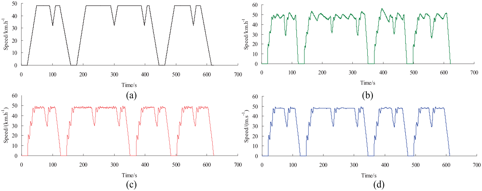
Test results of speed tracking control: (a) target speed, (b) PID control, (c) FNN control and (d) proposed method.
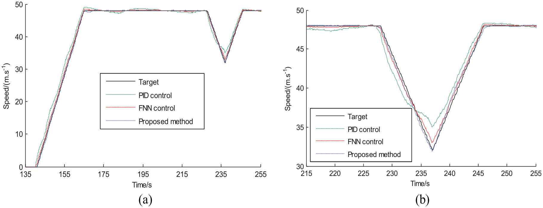
Comparison of speed tracking control: (a) speed tracking comparison curve and (b) Partial enlargement curve comparison.
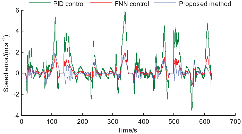
Speed tracking control error comparison.
To verify the adaptability of the proposed control methodology for the EDDVRD, the experiment of speed control interference from the driving resistances is conducted. Except for the target speed of 48 km/h, the target speed of 56 km/h is another driving cycle condition of the vehicle durability emission test. The test results of speed interference in different driving conditions are shown in Figure 13. It can be seen from Figure 13 that the proposed method in the paper can inhabit the change of speed caused by interference. The change of test conditions, such as improving road resistances, getting rid of road resistances and getting rid of wind resistances when the test is conducted, has little impact on the speed tracking control. In all kinds of conditions, the EDDVRD using the proposed control method can accurately track the target speed, which is 56 km/h here, and the speed control error is within the tolerance of ±2 km/h, which can meet the requirements of national test standard. The above test results show that the proposed method in the paper has a good adaptability. Besides, the comparison of the speed controller characteristics among the PID control, the FNN control and the proposed method is made in Table 2. 17 It shows that the proposed method is more appropriate for the speed control of the EDDVRD.
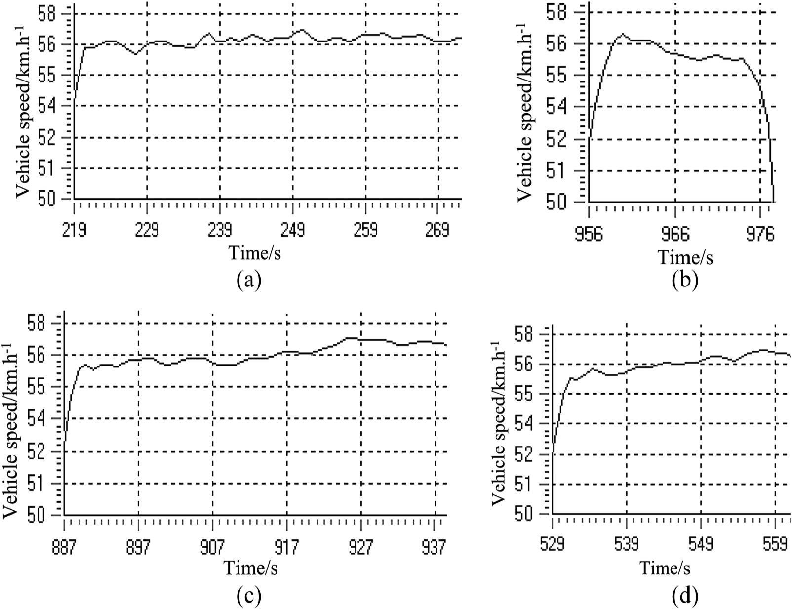
Test results of speed interference in different driving conditions: (a) normal test, (b) improving road resistances, (c) getting rid of wind resistances and (d) getting rid of road resistances.
Comparison of the different controller characteristics.
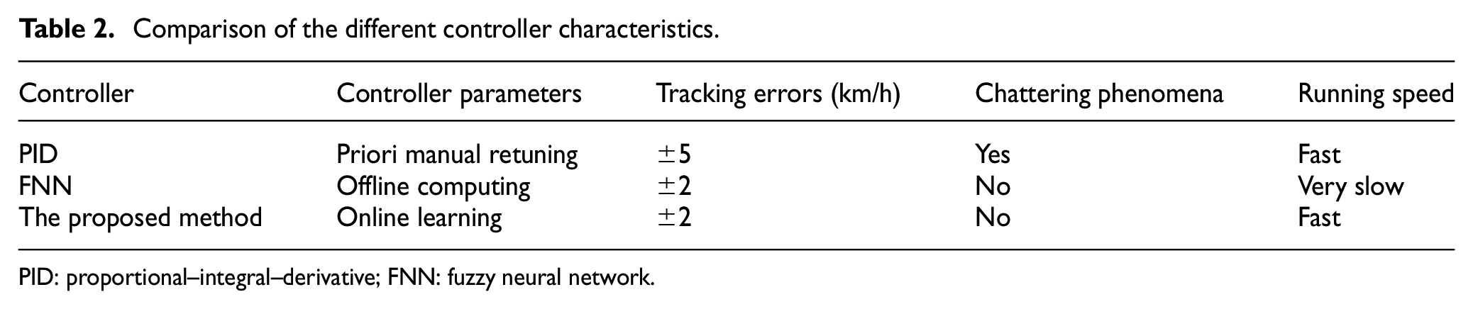
PID: proportional–integral–derivative; FNN: fuzzy neural network.
The mileage deviation of the EDDVRD using a different control method is shown in Table 3. In each speed–mileage constraint point, the maximum mileage deviation of the EDDVRD using PID control, FNN control and the proposed method in this paper is, respectively, 0.18, 0.4 and 0.02 km. The reason of is that the speed tracking accuracy of PID control is large, the FNN algorithm is difficult, and the FNN computing time is long. The proposed method in the paper has not only good speed tracking accuracy but also small mileage deviation.
The mileage deviation.
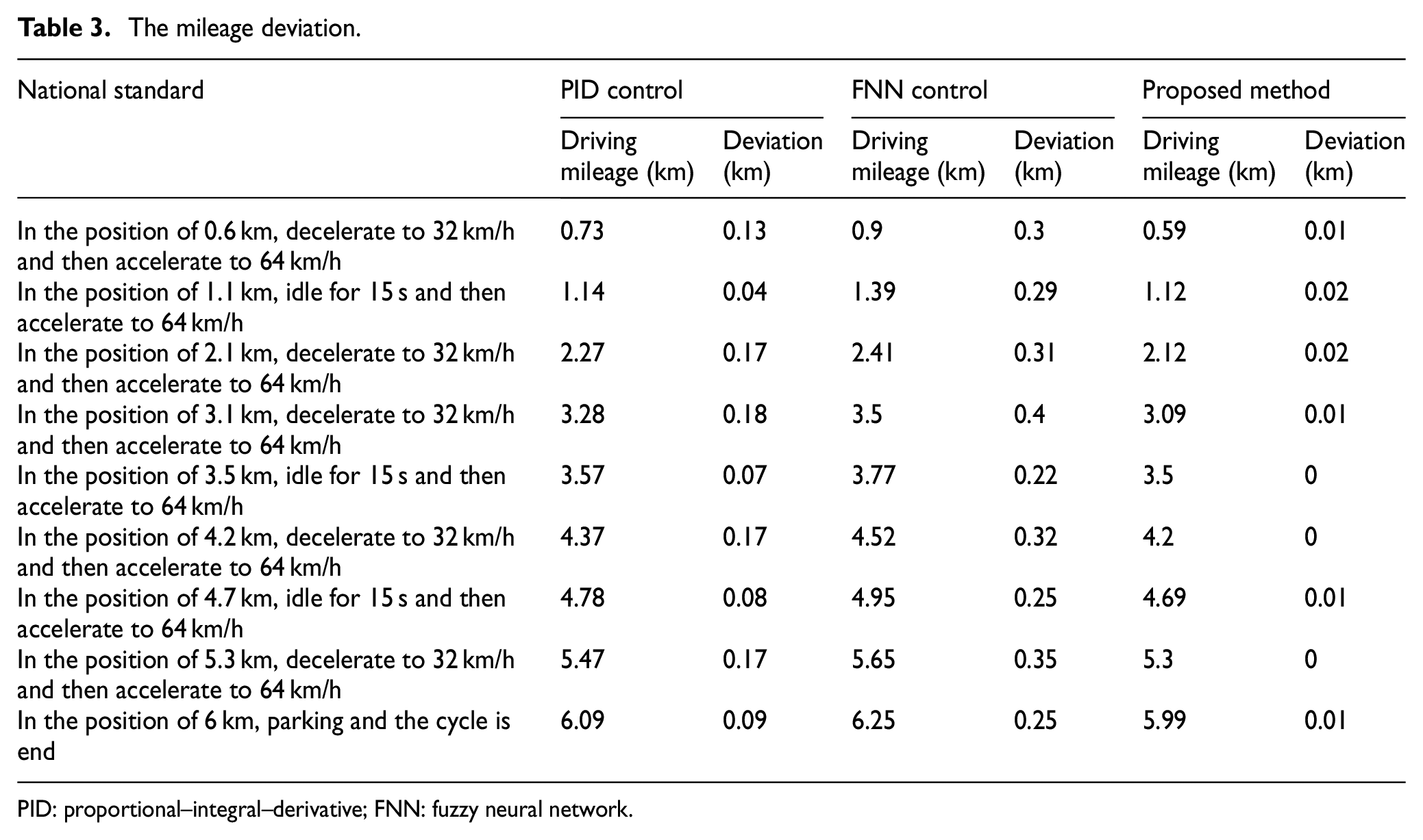
PID: proportional–integral–derivative; FNN: fuzzy neural network.
Conclusion
To solve the shortcomings of the existing control method for an EDDVRD, including large speed tracking error and large mileage deviation, the paper proposed a new adaptive speed control method for the EDDVRD based on fuzzy logic. The EDDVRD driver adapts an electromagnetic linear motor as its drive mechanism. The control system structure is presented. The coordinated controller for throttle mechanical leg and clutch mechanical leg and the switching controller for throttle mechanical leg and brake mechanical leg are presented. In addition, an adaptive speed controller for the EDDVRD is proposed, so that it achieves the accurate tracking of desired speed. Experiments are conducted using a Ford FOCUS car. Performances of the proposed method, PID, and FNN are compared and analyzed.
Experimental results demonstrate that the proposed control method can accurately realize the vehicle speed tracking for specific national automotive test standard, and the vehicle speed tracking error meets the requirements of national vehicle test standards. Besides, the proposed method can inhabit the change of speed caused by interference, and the change of test conditions has little effect on speed tracking control. Furthermore, the mileage deviation for the EDDVRD using the proposed method is smaller than that of FNN control and PID control. Experimental results show the effectiveness of the proposed method.
Footnotes
Declaration of conflicting interests
The author(s) declared no potential conflicts of interest with respect to the research, authorship, and/or publication of this article.
Funding
The author(s) disclosed receipt of the following financial support for the research, authorship, and/or publication of this article: This project is supported by National Natural Science Foundation of China (Grant No. 51675281), Six Talents Peak Project of Jiangsu Province (Grant no. 2015-JXQC-003) and the Fundamental Research Funds for the Central Universities (Grant No. 30918011101).