
Abstract
This article presents the development and control of a two-wheeled mobile robot as the base of a human carrier for an amusement/transportation vehicle. The robot has a combined structure of two systems: a line tracking mobile robot and an inverted pendulum system that maintains balance while following a line on the floor. The mobile robot is purposely designed to carry a human operator or humanoid arms. The robot has the capability to follow the line on the floor using visual feedback, as well as maintaining its balance on two wheels. A visual servoing technique allows the robot to follow the line on the floor captured by a camera as the desired trajectory. Controllers are designed to have good line tracking and balancing performance using sensor fusion techniques. Experimental studies involving the robot following a line demonstrate the feasibility of it being an amusement vehicle.
1. Introduction
A balancing mechanism is one of the most important characteristics of dynamic systems that require a stable balancing posture to perform given tasks. The human body is a good example of a structure that uses balancing mechanisms in everyday life to stand, walk and run. Humans learn balancing skills over many years, from crawling as a baby to standing as a child.
Recently, human balancing skills have been endowed to dynamical systems. A robot that mimics a human being's balancing mechanism is called a humanoid robot [1–4]. If the balancing mechanism is broken in the dynamical system, the system becomes unstable. Therefore, robust balancing mechanism is quite an important skill in the dynamical system and requires a sophisticated control mechanism based on accurate sensing techniques.
One typical well-known system for balancing is the inverted pendulum system that consists of a cart and an inverted pendulum. The cart moves on the fixed rail track to balance the inverted pendulum. The goal of the inverted pendulum system is to control both the balancing angle and the position as desired. Control of the inverted pendulum system is quite challenging since a single input force has to control both angle and position, as in a single-input multiple-output configuration. More challengingly, combining two inverted pendulum systems together in the x and y-axes yields a two degrees-of-freedom (DOF) inverted pendulum system that moves on a plane [5]. Other variations of inverted pendulum systems have been presented in the literature [6–8].
Replacing the fixed track of the inverted pendulum system with two wheels adds another degrees-of-freedom (DOF) to allow navigation on the plane and this forms the mobile inverted pendulum system whose structure is a combination of two systems, a mobile robot system and an inverted pendulum system [9–19]. Since wheels can move on the plane, control of the mobile inverted pendulum system becomes more difficult to consider an additional heading angle to be controlled. Thus, for successful control of the mobile inverted pendulum system, three variables, namely a balancing angle, an orientation angle and a position should be controlled properly by input torques to drive the wheels.
Recently, the concept of a mobile inverted pendulum system has been applied to commercial service robots such as a personal transportation vehicle called Segway [9]. The reasons of using mobile inverted pendulum systems as a transportation vehicle are better manoeuvring and turning control in narrow spaces [10].
Successful commercial market of Segway has attracted many researchers' attention to develop and control mobile inverted pendulum systems as in the category of service robots. Movement of Segway is controlled based on the change of the centre of gravity by shifting the body and by manipulating handles. Thus, driving control of the Segway is not easy for beginners wishing to stabilize the vehicle.
The small-sized JOE has also demonstrated successful balancing control performance [11]. Control of the mobile inverted pendulum system based on system modelling has been presented [12–14] and a disturbance observer has been designed to control the mobile inverted pendulum system [13]. Interaction control of a mobile inverted pendulum system with other objects has also been presented [14, 15]. Compensation for the drift problem of a gyro sensor has been addressed to obtain an accurate angle [16]. Several balancing robots called BalBots have been developed and controlled with various control algorithms [17–19]. BalBot I and II from the BalBot series, have a simple structure of a slender rod for the pendulum with a two-wheeled balancing mechanism. Control of BalBot I and II has been achieved with linear controllers with the help of a neural network controller. A multi-layered perceptron network is used and implemented on a DSP 6000 series for BalBot I [17] and the radial basis function network is used and implemented on DSP 2812 for BalBot II [18, 19]. The design of BalBot III is quite different from previous ones: it has two arms instead of a single rod on the balancing platform so that it can play boxing games and is called BoxingBot [20].
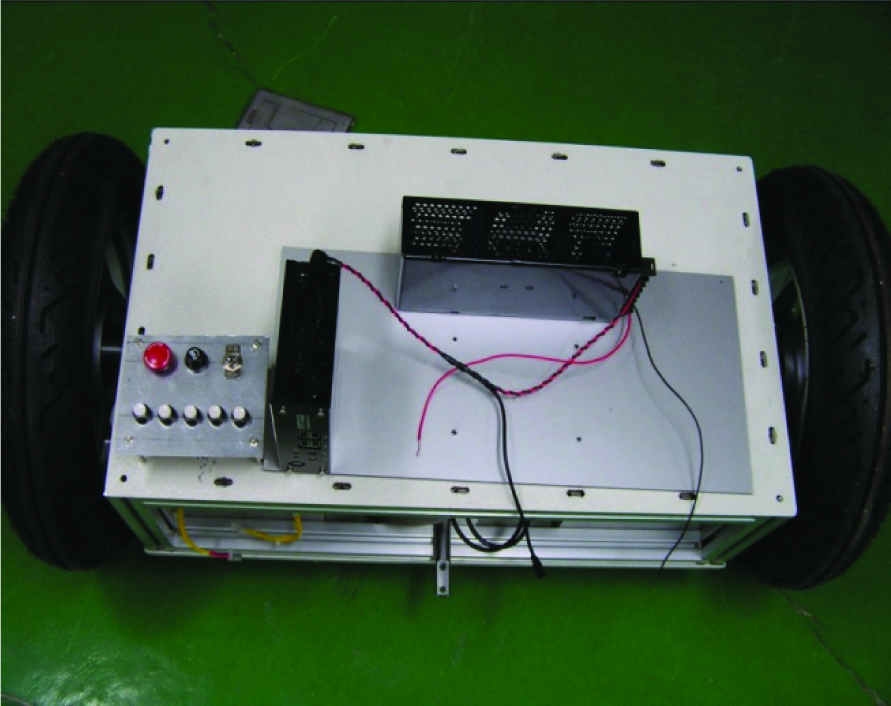
Borrowing the concept of balancing control from two-wheeled mobile robots, this paper presents a new model for the BalBot series called AmuseTransBot, as shown in Fig. 1, which is purposely designed for carrying human beings for entertainment and service in an amusement park. The base of the AmuseTransBot is designed and developed to carry a human being as a personal transportation vehicle or to carry a humanoid robot arm [21]. A mobile inverted pendulum, BalBot IV is presented [22].

Concept of Human-carrying BalBot, AmuseTransBot
The goal of this paper is to summarize [22] how the bottom part of the human-carrying BalBot is built and tested to have a robust balancing performance while following a line on the floor captured by a CCD camera. The visual servoing control technique of the human-carrying BalBot is employed to follow the line while maintaining balance. A linear controller is designed to achieve stable tracking performances when balancing with sensor fusion techniques. Line tracking experiments are demonstrated to show the control performance of the human-carrying BalBot.
2. Design of Human-carrying BalBot
The size of the human-carrying BalBot is designed to be larger than the previous BalBot series. The purpose of the human-carrying BalBot is to carry human beings as a transportation vehicle. The bottom part of the whole system is designed using a CAD program, as shown in Fig. 2. Fig.2 (a) shows the overall shape of the human-carrying BalBot and Fig. 2 (b) shows the inside of the BalBot. The BalBot has two wheels and two supporters to prevent it from falling down. The inside of the housing structure of the DC motors and batteries is shown in Fig.2 (b).

CAD Design of the human-carrying BalBot
3. Kinematics
The BalBot is a two-wheeled drive mobile robot with an inverted pendulum structure. The kinematics of the BalBot is similar to that of a wheeled drive mobile robot. Fig. 3 shows the coordinates of the BalBot. Since the BalBot is a non-holonomic system, position x, y and the orientation (heading) angle φ should be realized by two wheels.

Coordinates of BalBot
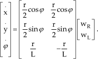
The Cartesian velocities have a relationship with a linear velocity v and an angular velocity φ of the robot:

where φ is the heading angle, d is the distance between the centre of the actuating axis and the centre of gravity,
In our system the wheels are designed and assumed to be located in the centre of the body, such that d = 0. Therefore, the relationship becomes simplified.
4. Control Schemes
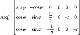
The BalBot is kinematically constrained and has the non-holonomic characteristic dynamic equation:

where M(q) is the 6×6 inertia matrix, C(q,q) is the 6×1 vector of Coriolis and centrifugal torques, G(q) is the 6x1 gravitational torques, λ is the Lagrangian multiplier, P is the 6×2 input transition matrix and τ is the 2×1 vector of the actuator joint torques when the joint vector is given by q = [x,y,φ,θ,θR,θL]T where θ is the balancing angle. Since the system is kinematically constrained in the lateral direction, we have the constraint matrix, A(q):
To eliminate the Lagrangian multiplier, we select the matrix S to satisfy the relationship of STAT(q) = 0.

Since we have a Jacobian relationship of q = S(q)ν, q = Sν + Sν, multiplying ST to (3) yields the Cartesian dynamic equation:

whereD = STMS, H = STMSν + ST(C + G).
Controlled variables include a balancing angle θ, an orientation angle φ and a position p. A PD controller is used for controlling the balance angle and PID controllers are used for position and heading angle control. A combined control method for each wheel is given as:

where Kii is the controller gain, ω = φ, v = p and φd,θd,pd are the desired orientation angles, a desired balancing angle and a desired position, respectively. The desired balancing angle is set to zero and the desired orientation angle is calculated using a camera. The corresponding control block diagram is shown in Fig. 4.

Control block diagram of human carrying BalBot
5. Experimental Studies
5.1. Experimental Setup
The overall hardware system structure is shown in Fig. 5. The experimental setup consists of the BalBot with a CCD camera, a PC and the control hardware. The line on the floor can be detected by the CCD camera and the captured images are processed in real time on a PC to generate the desired trajectory (pd and φd). Each joint torque command can be calculated from a control algorithm that forms errors between the line trajectory captured from a CCD camera through the kinematics of an actual trajectory. The robot position p and the orientation angle φ are calculated by encoder signals. The balancing angle θ is measured from a fused algorithm by a tilt and a gyro sensor.

Overall hardware system structure
Based on the kinematic equation given in (2), state variables for the controller design are defined and obtained from sensors as shown in Fig. 6. Encoder measurements are used to calculate the position and orientation of the robot through kinematics and tilt and gyro sensors are used for detecting the balancing angle, as shown in Fig. 6. FPGA chips are used for collecting encoder data and converting analogue signals to digital.

Control variables of BalBot
Encoder counters embedded in FPGA count the number of rotations of the motors to provide position p. Then velocity information v is estimated through the finite difference method. Captured tilt and gyro sensor data are digitized by an AD converter and used in the complementary filter to generate the balancing angle θ and the angular velocity θ. The mechanical layout of the BalBot is shown in Fig. 7. The control hardware has DSPs and a FPGA to control the wheel motors, as shown in Fig. 8.
Experimental setup of BalBot

Control hardware: DSP and FPGA
Fig. 9 shows the GUI on the screen that describes the laser sensor data and captured image data. From the image data, the line trajectories are calculated for the robot so that it follows the desired trajectories.

Line capturing monitor
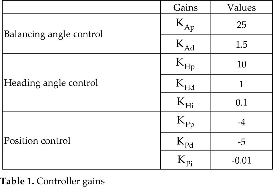
The PD and PID controller gains are listed in Table 1. Gains are selected based on experimental studies. Several experiments were conducted to decide which controller gains are suitable.
Controller gains
5.2. Experimental Results
5.2.1. Balancing control test
Firstly, a balancing control task was tested. The BalBot was initially standing and then external disturbance was applied to the system. Fig. 10, 11 and 12 show the response results of the balancing angle, the position and the heading angle, respectively. Fig. 10 shows an interesting result that indicates that the robot is balanced not at zero but within a 0.1 radian. This behaviour occurs when the actual centre of gravity (COG) of the system is not located exactly in the centre of the system body, but deviates slightly from the COG point. At around 2 seconds, there is an intentional disturbance from an external hit, but the BalBot maintains balance well. We see from Fig. 11 that a small offset in position occurs after the external hit. The corresponding heading angle is shown in Fig. 12.
Balancing angle error of BalBot

Balancing position error of BalBot

Heading angle error of BalBot
5.2.2. Line tracking control task
Next, the line tracking control performance is tested. The red line is drawn on the green floor, as shown in Fig. 13. The robot is required to follow that red line. Fig. 13 shows the actual movements of the BalBot when following the line. We see the successful line-tracking performances from the starting point to the ending point as desired.

Line tracking performances of BalBot
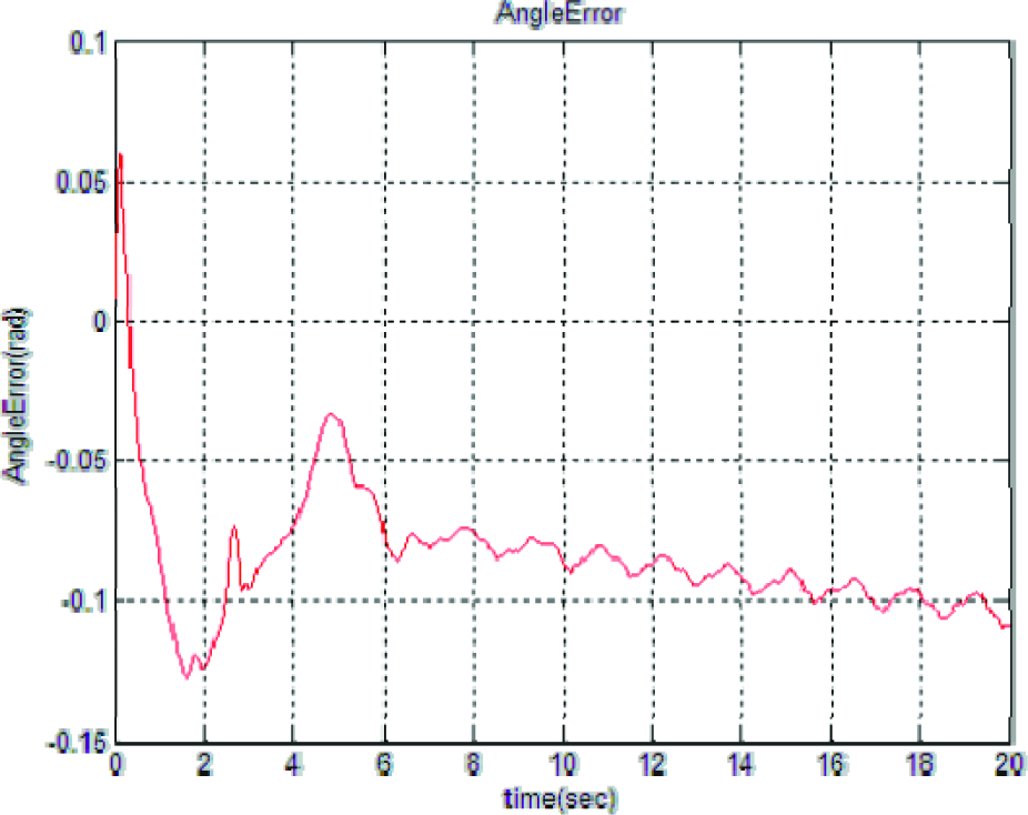
The corresponding results are shown in Fig. 14–18. Fig. 14 shows the successful balancing angle result. The position tracking error between the desired trajectory captured by the camera and the actual trajectory is shown in Fig. 15. The corresponding heading angle is shown in Fig. 16. We see the actual trajectory of the BalBot on the x-y plane in Fig. 17. The corresponding heading angle is also shown in Fig. 18.

Balancing angle error of BalBot
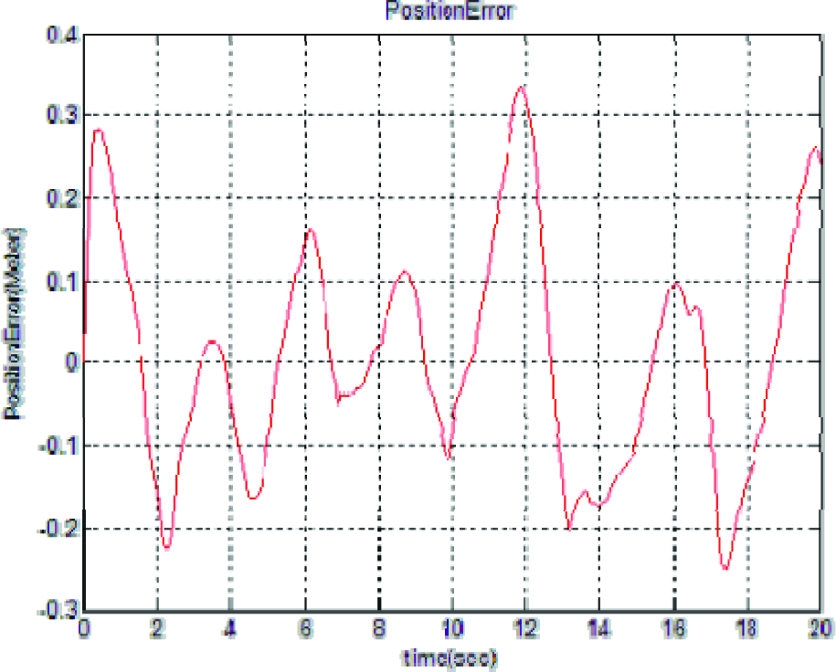
Position error of BalBot

Heading angle error of BalBot
XY Position of BalBot

Heading angle of BalBot
6. Conclusion
A base of the balancing robot was designed and implemented to carry human beings for amusement and service applications. The robot is required to follow a line on the floor while balancing. Image processing of captured images from a CCD camera on a PC provides the desired trajectories for the robot to follow. Necessary control hardware such as a DSP and an FPGA chip is implemented to generate control torque for each wheel. Multi-sensors such as tilt and gyro are fused with a complementary filter to detect the balancing angle accurately. Relying on linear controllers, the BalBot achieves successful line tracking performances. In the future, the BalBot will be equipped with a seat for a human operator.
Footnotes
7. Acknowledgements
This work was partially supported by the Korea Research Foundation under a grant from the Basic Research Program in 2008 and 2010.