
Abstract
A kind of novel 2-DOF micromanipulator is designed and analysed based on the two scales of level amplifier principle, which adopts the flexure hinge to replace the traditional hinge. The kinematics, static and dynamic modelling are established, and the input stiffness and actual amplification ratios are calculated. Meanwhile, the finite element analysis (FEA) is applied in order to validate the calculation by using ANSYS software. Then, the theoretical, calculated and simulated values diagrams are compared. Thereafter, the stress and the natural frequency of the stage are also analysed to optimize the platform dimensions. Parasitic motion values are calculated and analysed, and their values are compared in a diagram. The Particle Swarm Optimization (POS) is applied to design and optimize the structure parameters, and finally the optimal structure parameters are obtained and the values of parameters are used by the finite element model (FEM). In addition, a dynamic equation and a suitable control flow chart are designed for the mechanism, and the control strategy is proposed accordingly. Finally, the simulation analysis of the stage control adopting the MATLAB software is performed.
1. Introduction
The development of the manipulator goes through several different periods, from large industrial robot to small medical robot to micro-biological medical robot. Robot manipulators can develop quickly, which is mainly attributed to rapid development of modern science and technology, and the gradual updating of electronics. In addition, it is significant that the robot manipulator can replace humans to complete some dangerous jobs, for example in high-temperature, toxic, and micro environments where humans are not able to work. The micromanipulator is one of the newly developed manipulators for studying small and micro worlds. Many countries and people have also studied and designed some different types of micromanipulators, which have many advantages including a large workspace, high natural frequency, and high resolution. At the same time, Ryu et al. [1] developed a XYθ micro-position stage consisting of the monolithic flexure hinge-based mechanism with PZT actuators: the system has a total translational range of 41.5μm and 47.8μm along the X and Y axes, respectively, and a maximum rotational range of 322.8arc sec. Culpeppper et al. [2] introduced a 6-DOF low-cost nano-manipulator using a planar compliant structure. The resolution is higher than 5nm in a 100nm×100nm×100nm work volume, and the open-loop errors are less than 0.2% of the full scale. Li et al. [3] designed a compact 2-DOF micromanipulator with the workspace around 180μm x 180μm, and the resolution is several nanometres. Yong et al. [4] proposed a flexure-based XY nano-position stage, which has the ability to scan over a range of 25μm × 2μm with a high scanning speed. The stage has its first dominant mode at. 2.7KHz., and the cross-coupling between the X and Y axes is low enough that the single-input-single-output (SISO) control strategy can be utilized for tracking control. Micromanipulators can have wide applications in biological/medical and micro-assembling engineering fields, which require a micro-hand to hold, inject, cut, manipulate, and assemble under a microscope, this task is difficult to achieve with a human hand [5], [7].
A novel 2-DOF micromanipulator is designed and studied in this paper, which has a higher precision and ease of control. In addition, the precision of manipulator can reach the nanometre level, while the piezoelectric ceramics employed as the driven elements can improve its control ability [8]. When a large size of manipulator platform is designed by applying the conventional design method, a rotational joint is used to realize rotation between two links, which easily causes errors due to frictions and clearances. Therefore, a large manipulator is usually used in industrial environments without strict precision requirements. A flexible hinge is selected as the rotation and transfer displacement component in this stage, which shows higher precision and fewer errors due to a whole-piece fabrication. Furthermore, it has many advantages compared with the conventional hinge, such as no mechanical friction, small volume, no backlash, and high sensitivity. The deformation principle of the material itself is applied in the flexible hinge micro displacement mechanism. Due to the limitation of the deformation itself, the level amplified principle is applied. The input displacement of the PZT is amplified by using the amplifier of the amplification mechanism, which can produce a large stroke for the platform. At the same time, the simulation analysis and optimization design are conducted by using the ANSYS and MATLAB software; moreover, a dynamic control equation is obtained and a suitable control strategy is used at the stage, which validates the results of this design.
2. Micromanipulator design
The displacement amplification, stress distribution situations, and the natural frequency characteristics of the rectangular notch joint and right circular notch joint are analysed and compared in [9], and the result is that the rectangular notch joint has advantages compared with the right circular notch joint. The rectangular notch joint is therefore selected as the hinge type of the micromanipulator in this paper.
2.1. Amplification ratio calculation
In real-world applications, one-scale level structure is normally not enough to meet the requirement of the micromanipulator, while two scales of level amplification, the principle of which is shown in Fig. 1, can translate to a bigger displacement. The two-scale amplification structure is constructed by adding two one-scale level structures in cascade, and the difference is that the input section of the last one-scale level is the output section of the former, which produces a displacement cumulative effect and lets the ultimate output displacement obtain the ideal effect.
In the Fig. 1, the point A is input point, points B and C are the transition points and the point D is the output point; at the same time, the points O1 and O2 are the rotation centre points. When an output force FA is given in the point A in the y direction, the limbs AB and CD turn mini-angles θ1 and θ2 around the centre points O1 and O2, respectively. The whole structure will therefore introduce the different displacements in terms of SA, SB, SC and SD in the points A, B, C and D in the y direction, corresponding to the “displacement loss” in terms of ΔXA, ΔXB, ΔXC and ΔXD in the x direction. The displacements and the “displacement loss” in the points B and C are equal, ‥ and ΔXB = ΔXC, respectively.
According to the geometrical relationship, the following displacement equations are derived in the y direction:


According to the amplification principle, the amplification ratio of the amplifier is the ratio of the output and input displacements. Recalling the equations (1) to (4), and considering the SB = SC, we can obtain the formula for calculating the amplification ratio:


Two-scale amplification
The amplification ratio is only a theoretical value calculated using the above equation; the actual value is less than the theoretical value because of the “displacement loss” in the y direction. However, the loss is generally ignored, so the theoretical value can be regarded as the actual value when the output quantity is calculated.
2.2. Single freedom flexible hinge amplification mechanism
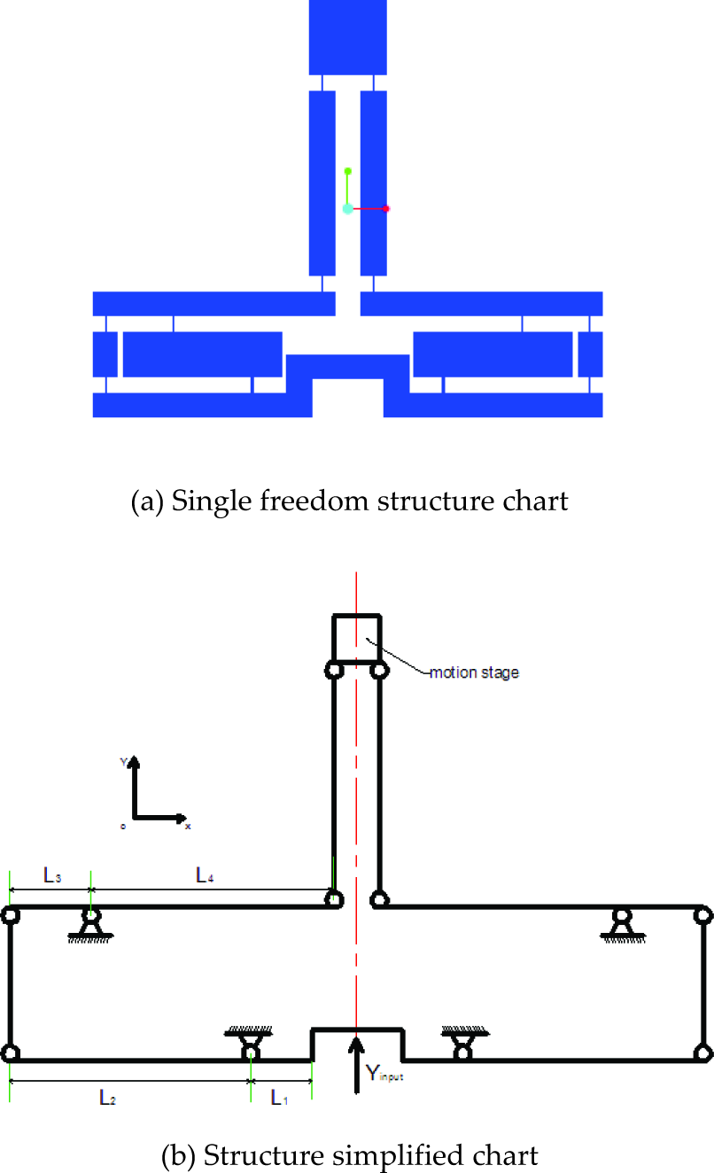
The level amplified principle is usually applied in the mechanism design to amplify the input parameter values; correspondingly, a larger output value can be produced. The input parameter values might be displacement, force, or torque. A single freedom manipulator amplification mechanism and its mechanical simplified diagram are shown in Figs. 2 (a) and (b), respectively.
We can observe from Fig. 2 (b) that the single freedom mechanism is symmetrical along the central line structure, which has a better decoupled effect than the unsymmetrical structure. The theoretical amplification ratio of the mechanism is λ = L2L4 / L1L3 according to the equation (5), so the output displacement that is produced by the amplification mechanism is λ times the input displacement that is produced by PZT 2 along the Y direction.
2.3. Design and structure of the 2-DOF micromanipulator
The single freedom manipulator platform is shown in Fig. 2, which is a single-input-single-output (SISO) system that has only one input and one output. It can only be applied in some simple systems. The two-input and two-output system is designed based on the SISO system; the whole structure chart is presented in Fig. 3. It is clear that the whole stage is composed of the motion chains in the X and Y directions. Piezoelectric actuators that are installed in the X and Y directions are selected as the platform's driving elements, such as PZT 1 and PZT 2, as shown in Fig. 3. Aluminium material AL7075 – T6 is selected to fabricate the stage. PST150 is selected as the type of PZT, whose driving voltage range is −30V~150V and whose largest output displacement is 75μm. The largest output displacement is only 54μm when the driving voltage range is from 0V~150V.
3. System modelling
In this section, the characteristics of the stage's kinematics, its static and dynamic properties, stress, input stiffness, and natural frequencies are analysed and validated. All investigations are prepared for the next-step optimized platform.
Single freedom schematic diagram.

A 2-DOF manipulator stage

Half of the displacement amplification mechanism and force analysis
3.1. Kinematics and static modelling
The theoretical values in the X and Y directions are the same because of the symmetry of the amplification mechanism. Input displacements (d1,d2) are given in the X and Y directions by the two PZTs, which can obtain corresponding output displacements (dx,dy) and forces (F1,F2), respectively. The displacement and force sizes of the stage can therefore be represented from the following calculation formulae.


where Kin and λ are input stiffness and the displacement amplification ratio of the stage, respectively.
From the above formulae, the static formula of the platform is related to the input stiffness of the stage. The input stiffness Kin and the amplification ratio λ cal should therefore be calculated first. The simple chart and the simple modelling of the rectangular hinge are shown in the Fig. 5. Every flexible joint has two dimensional compliances Cr and Cf that can replace the torsion and linear spring with their stiffnesses, Kr and Kf, which were analysed in [12]. It is supposed that an input displacement din is given by the PZT 2 in the Y direction; meanwhile, Fin and dout are the input force and output displacement, respectively.
The corresponding force is also half when the half structure is analysed according to the symmetry of the mechanism. The displacement amplification mechanism and the force analysis of the half structure are shown in Fig. 4. The following formulae can be produced by lever balance principle:
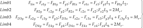
The relation of each node can be represented by the following equation:
where the torque Mr is produced after the small Δθ deflection occurs along the centre of the hinge from the inside of the flexible hinge, which is calculated by the following formula:

Substituting (9) into (8), the following formula can be derived:


At the same time, the relationship between Fo1y and Fo2y can be rewritten as:

Substituting (11) and (12) into (13) and considering (10), the relation to the input and output can be derived by:

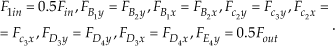
The following equation can be derived by applying the virtual work principle to the amplification mechanism simultaneously:

where Δyin and Δyout, are the input and output displacements, respectively; Fz1 and Fz2 are the axial forces of the flexible hinges along the axis direction in the points O1 and O2; and Δyz1 and Δyz2 are the deformations in the two points. The following formulae can therefore be derived by the force-balance relationship:


Rectangular flexible hinge diagram and simplified model

The input displacement yin is produced by the PZT2, the corresponding output displacement yout and the drift angle θ of the rectangular hinge; therefore, the following equation:

can lead to:

3.2. The stiffness of the platform analysis
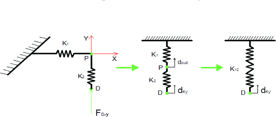
The stiffness of the platform refers to the stiffness excepting the amplification mechanism. The stiffness conversion relationships are shown in Fig. 6.
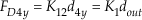
The output force Fy is expressed in the following equation:

where K12 is the whole stiffness and d4y is output displacement after the amplifier amplification mechanism.
The corresponding output displacement is dout when input displacement din is given in the Y direction, where it is expressed by the P point in Fig. 6. It is supposed to have a rotational angle γ in the chain 1, so the potential energy of the chain 1 can be obtained by
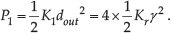
where

At the same time, substituting (25) and (19) into (14), the rotational deformation Δθ can be derived by: At the same time, γ = dout / L6 is derived by the deformation of the flexible hinge. The following formula can be obtained:

The stiffness of chain 2 will also be obtained by the relationship between the series-parallel of the chain

So the total stiffness of the platform is expressed by:

In addition, the following formula can be produced according to the relationship between the force and the displacement:
The following equations can be derived from the force-balance relationship:

Substituting (10), (16), (17), and (25) into (15), the following new relation can be expressed by:

Meanwhile, substituting (16), (17), and (19) into (26), another new equation can be obtained by:
where
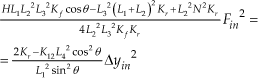
The input stiffness of the stage can be calculated from the above equation (27):


Then, substituting (29) into (19), the output displacement Δyout after amplification can be rewritten as:
XY stage's stiffness modelling
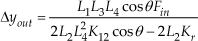
The amplification ratio of the whole stage is therefore:
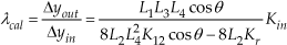
Main parameters for the XY stage
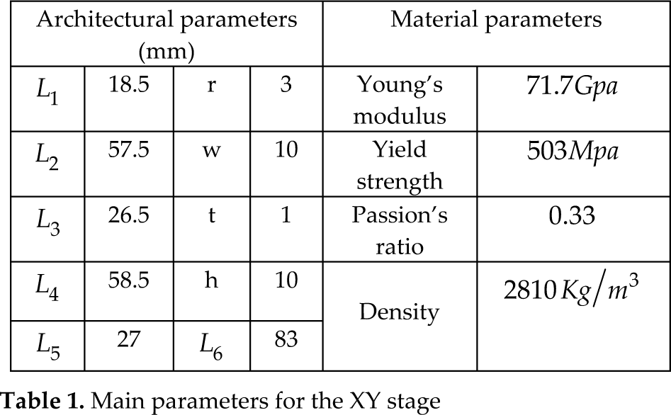
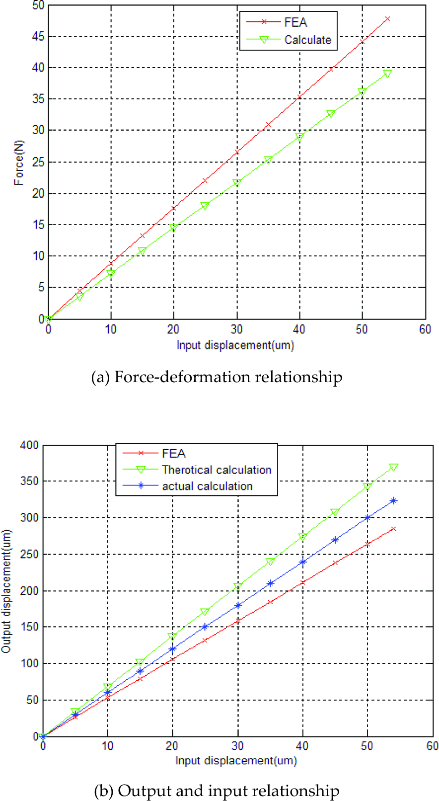
The parameters of joints are given in Table I. In addition, the force-deformation and the input and output displacement relationships are shown in Figs. 7(a) and (b), respectively. It can be observed that the simulated and calculated stiffness values are very close in Fig. 7(a), which validates the accuracy of the stiffness model in (28). According to the ANSYS software analysis, in Fig. 7(b), the amplification ratio is 5.88 and the actual calculation value is λ cal =5.99 using the equation (31), which is less than the theoretical amplification ratio 6.86. From Fig. 7(b), we can see that the amplification ratio of actual calculation is between the theoretical value and simulation value according to FEA, which validates the equation (31) as a useable result. The “lost motion” comes from the fact that the elements besides the notch hinges are not fully rigid and the deformation of the joint itself. All these will be discussed in the next part.
When a force (17.66N) is applied at the PZT 2, the corresponding input (20μm) and output (117.597μm Fig. 8(a)) displacements of the output platform are obtained to determine the input stiffness and amplification ratio. Taking the finite element analysis (FEA) as the ‘true’ value for the input stiffness (0.863N/μm) of the stage, we can calculate the input (0.725N/μm) stiffness of the stage using the above formula. The deviation of the two methods is 15.99%. The stress distribution diagram is shown in Fig. 8(b); the maximum stress (64.39MPa) is no more than the yield strength (503MPa), when the input maximum displacements are 54μm in the x and y directions.
The results of the FEA and analytical calculation comparison

Finite element analysis of the XY stage
3.3. Workspace and stress analysis
It is assumed that the As denotes the maximum stroke of the PZT, so the workspace range of the XY stage will be derived by λAs × λAs, as long as the maximum stress due to the rotational stress σ r and the axial stress σ t of the flexure hinge remain within the allowable stress σ of the material. Moreover, the axial stress is less than the rotational stress from the bending deformations, because the rotation of the flexure hinge is taken into account to calculate the maximum stress of the stage. The following formula can therefore be obtained:

where σ y and s >1 denote the yield strength of the material and an assigned safety factor, respectively.
Since a flexure hinge bears a bending moment around its rotation axis, the maximum rotational angle θmax occurs when the maximum stress reaches σmax. This occurs at the outermost surface of the thinnest portion of the hinge, attaining the yield strength σ y .
The following relationship between the maximum bending stress and the maximum rotation deformation of the flexure hinge has been derived in [13]:

where E is the Young's modulus of the material.
It is assumed that the input displacement is the maximum actuation displacement As of the PZT, and the maximum angle θmax occurs when the linear displacement is dmax = λ cal A s . According to the geometrical property of the platform, the maximum angular deformation may occur on the hinge belonging to limb 4, as shown in Fig. 4.
The maximum rotational angles occurring on the limb can be derived by the following formula:

Substituting the maximum rotational angle described by (33) into (32) and considering (31), we can obtain the following relationship formula:

The above formula also provides a guideline for the design of the stage dimension without the risk of inelastic deformations.
3.4. Dynamic model and natural frequency analysis
3.4.1. Dynamics model
The input-displacement variables δ = [δ1, δ2]T are chosen as the generalized coordinates. As shown in Fig. 3, the potential energy of the whole mechanism can be calculated by:
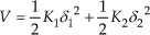
where K1, K2 are the input stiffness in x or y direction, respectively.
As shown in Fig. 9, the hinges for b, c, d and f have only rotational motion, the hinge e has rotational and translational motions, while the hinges a and g and the motions stage o have only translations. It is assumed that every branched chain connects to every flexure hinge by a rigid body, so the kinetic energy of the whole mechanism, except for the motion stage o, can be calculated by the following equation:

The kinetic energy and potential energy can be substituted into the following Lagrange's equation:

where δ i and Fi denote the i – th generalized coordinate and actuation force, respectively. Substituting equations (36) and (37) into (38), we can obtain the general dynamic equation:

Chain A

where M = diag{M} is the mass matrix, K = diag{K} is the stiffness matrix, and F = [F1, F2] T is the vector of the actuation forces, respectively, with the following notations:


3.4.2. Natural frequency
The natural frequency of the micromanipulator is the important index for analysing the motion. It is therefore necessary that the natural frequency is given in the paper.
The undamped free vibration of the mechanism can be derived by the following equation:

According to the vibration theory, the model equation of undamped system platform can be described as:

Where λ i and φ are the eigenvalues and eigenvectors in the i – th model of the stage. And the eigenvalues can be calculated by the following formula:

The natural frequency of the whole platform can be derived by the following equation:

As a case study, with the physical parameters described in Table I, the natural frequency (61.915HZ) of the XY stage can be calculated from the dynamic model in the y direction by above formula. Moreover, the frequency (56.723HZ) of the model is simulated in the y direction by using finite element analysis (FEA). The two values have a deviation of 8.39%. The equation (38) is therefore validated.
4. Analysis of the parasitic motion
Parasitic motion caused by a single direction freedom motion is a minimal movement, which is another single direction freedom motion and has a large effect on the stage's accuracy. In the micromanipulator field, it is therefore essential to analyse the organizational parasitic motion. In this section, we will analyse how great an influence the parasitic motion of mechanism has on the mechanism accuracy. The mechanism has two degrees of freedom, and is thus able to cause the parasitic motion e2 (Fig. 10(b)) and the parasitic motion e1 (Fig. 10(a)) of the half amplification mechanism itself in the Y direction with an input displacement dx in the X direction. It is assumed that the rotational angles are α and β, calculated in Fig. 10(a) and Fig.10(b) below, respectively. The following formulae can be expressed according to the geometrical relationships:


where


Deformation and parasitic motion in the Y direction caused by an input dx
We can observe from Fig. 10(a) that this is a symmetrical amplification mechanism. Therefore, there will be two parasitic motions +e1 and -e1, which are cancelled out with opposed direction and equal size in the Y direction. In Fig. 10(b), the parasitic motion of one side chain is caused by another, which cannot be cancelled out because of asymmetry.
In order to further eliminate the influence of size, we assume that there is an input displacement dx = 20μm in the X direction. The initially designed mechanism's main dimensions are shown in Table I. The output value of the parasitic motion can be derived by:


The absolute error δ x-y produced by the parasitic motion can be calculated with the following formula:

We can see from the above result that the parasitic motion is minimal compared with the initial input displacement.
In the following analysis, we calculate the actual amplification and parasitic motion by using ANSYS software. Two situations can be isolated: one has no constraints in the Y direction while the other has constraints. In the former situation, when the joint has a rectangular hinge there is a parasitic motion d1‘ = 117.597μm, e2’ =1.04μm in the X direction amplification and Y direction, respectively. A “displacement loss” will be produced when the movement is amplified and transferred to the end-effector because of the characteristics of the flexible-hinge deformations. However, the actual movement is d1“ = 105.46μm. In the latter situation, there is a small parasitic motion of only 0.0046μm, while the sizes of the X direction amplification and actual amplification are d1‘ = 115.94μm and d1” = 104.58μm, respectively. Figs. 11(a) and (b) express the relationships between the parasitic motions based on FEA and calculated errors in the two methods, respectively.
From the above analysis, we can observe that a greater effect is caused by the parasitic motion produced by the amplification mechanism stage and flexible hinges, which ultimately affects the stage's accuracy. The stage's parasitic motion is therefore not only related to the mechanism itself, but also to the deformation of the hinges.
5. Optimal design of the mechanism
In this section, the mechanism parameters will be optimized, and the best values will then be derived. The conventional optimization algorithms search for the optimal solutions from some selected initial values, which will easily fall into the local optimum. Currently, the genetic algorithm (GA) and particle swarm optimization algorithm (PSO) are generally applied in the mechanism design, which can be realized in the MATLAB environment [9]. The basic idea of the genetic algorithm is to search through a group of initial values called the population of the representing of the optimal values. The population has fixed numbers and is composed of the genetic code form; each individual is called a chromosome; different chromosomes go through replication, crossing and variation to generate new chromosomes; meanwhile, each chromosome is also evolving generation after generation according to the law of the survival of the fittest, finally arriving at optimal condition after evolution over several generations. The basic idea of the particle swarm optimization algorithm is mainly inspired by flocks of birds foraging for food. Since the PSO is easier to realize than the GA, it is adopted to optimize the minimal volume of the micromanipulator stage.

Parasitic motion
It is supposed that the global optimum can be found in searching areas when the initial positions of particles are randomly selected. Each particle has an optimal value pi,b, and the whole particle swarm also has a best value gb. Each particle can therefore update its own velocity and position according to the following formula:

w τ1i and τ2i are the random numbers between the interval [0, 1], ω(k) is the weighting function, and a1 and a2 are the acceleration constants, respectively.
5.1. Optimization algorithm
As far as a material with a specific thickness (w = 10mm in this research) is concerned, the eight parameters (L1,L2,L3,L4,L5,L6,r,t) need to be optimized since the others can be determined by considering the structure requirement of the PZT. The amplification ratio of the stage is specified to guarantee a travel range no less than 120μm for the mobile platform. In addition, the input stiffness should not exceed the minimum stiffness of the adopted PZT (KPZT=10N/μm). Then, the designed platform can undergo its assigned task without failure. The lower and upper bounds of the parameters should all be determined to guarantee the compact structure. Considering that the analytical models overestimate the stage performance with the derivation of 20%, a compensation factor ζ = 0.8 is adopted in the optimization process to compensate for the error of the derived model. With the natural frequency of the stage being selected as the objective function, the optimization can therefore be stated as follows:
Maximize: the natural frequency (f)
Variables to be optimized: L1,L2,L3,L4,L5,L6,r,t.
Subject to:
Input stiffness value: ζKin ≤KPZT; Amplification ratio: ζλ
cal
≥ 6; Free of inelastic deflection guaranteed by (34) with the safety factor: s = 1.5; The ranges of the parameters:
15mm ≤ L1<20mm;55mm ≤ L2 < 60mm; 25mm ≤ L3 < 30mm; 55mm ≤ L4 < 60mm; 25mm ≤ L5 < 30mm, 60mm < L6 < 90mm; 2mm ≤ r ≤ 6mm;0.5mm ≤ t ≤ 2mm.
5.2. Optimization results
The optimization issue is composed of eight variables. It is assumed that this corresponds to the searching space dimensions. The acceleration constants are a1 and a2; the weight function w is 2. The population size, maximum iterations, and the precision are 40, 1000 and 10e-6, respectively. The optimization results can be derived by the PSO toolbox [10]. The optimized dimensions can be obtained as:
The corresponding maximum natural frequency is: 66.79Hz.
5.3. Performance test with FEA
To test the performance of the optimized XY stage, FEA is applied for this model. In the static finite element model (FEM), the input displacement of the PZT2 is 20μm; the two-axis deformations of the stage are depicted in Fig. 12.

Deformations of the XY stage along the (a) y-axis and (b) x-axis with input of y direction
It is observed that the output displacement is 110.87μm and the corresponding input force is 19.37N; the input stiffness is 0.97 N/μm and the amplification ratio is 5.54. Meanwhile, as shown in Fig.12(c), the maximum stress is 64.54MPa, which is far less than the allowable stress (503 / 1.5 = 335.3MPa).
All the values analysed above are close to the theoretical calculations after the optimisation, which validates the design parameters.
6. Dynamic modelling and simulation
6.1. Dynamic modelling
Dynamics investigates the causes of motion produced by forces, the relationship between the force/moment of the body and the body motion. The law of motion stage is studied in this section. The law of motion of the stage is described by applying the mathematical model under the PZT actuator effect. The dynamic modelling of the whole structure is established according to the nonlinearity of the PZT actuator.
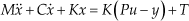

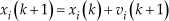
Where the parameters M, C, K, and x are the mass of the manipulator, damping coefficient, input stiffness of the stage and X direction displacement, respectively. P is the piezoelectric coefficient, and u is the input voltage of the PZT actuator. The parameter y is the output variable of the nonlinearity dynamic hysteresis, while α,β,γ,δ are the parameters that influence the curve shape of the hysteresis. In addition, the T is the unknown external disturbance [14].
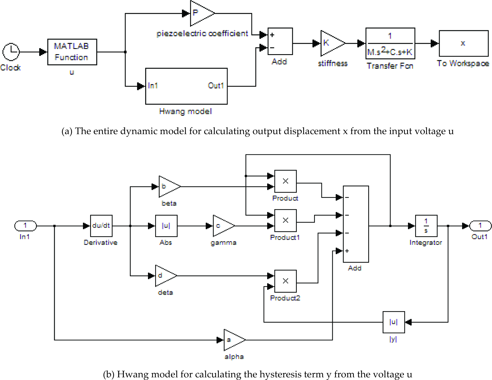
The Hwang model is selected as the piezoelectric hysteresis model [11]. The simulation of the whole stage dynamic model is described in Fig. 13(a) and the Hwang model for the hysteresis model is represented in Fig. 13(b). The closed-loop chart between the input voltage and X direction displacement can be derived by system simulation.
According to the Laplace transformation, the following transfer function of motion platform can be derived:

where X(s) and U(s) are the input and output of the Laplace operators, respectively. s is the complex frequency, ω is the natural angular frequency, and
Dynamic simulation model implemented with MATLAB/SIMULINK
6.2. Design of the feedback compensation control strategy
A feedback compensation PID control strategy is applied in the micromanipulator, the advantage lies in that it can compensate the output displacement error caused by the piezoelectric hysteresis. The merit of feedback is that it can adaptively adjust the error between actual output value and desired output value caused by the hysteresis, and effectively reduce the source of error. A lot of research works have been carried out on the error compensation controller design. The feedback compensation with PID controller is applied and feedback compensation based on the Preisach model is used, which are called double composited systems. The double composited system can eliminate the hysteresis system error. A PID controller is used, which cannot control the displacement directly, but controls the voltage. Therefore, the platform accuracy is improved and the controller has the advantages of fast response time and shorter adjust time.
The block structure diagram of a double feedback PID control composited system based on the Preisach model is shown in Fig. 14. It can be seen that input and output displacement signals are target and actual displacements, respectively; e is the error between objective displacement and actual displacement, which changes with the PID feedback voltage signal from the PID controller; u is the gap between the PID feedback signal and feedback compensation signal on the Preisach model [15], and is also called the final input signal of the motion.
The numerical values of the various parameters are determined first, and then the simulation command is started when applying the MATLAB/SIMULINK software for a simulation. The relationship between the output displacement and voltage, as well as the relationship between the voltage and time, will be derived by the above dynamic simulation.
7. Conclusions
The features of the rectangular hinge are discussed and analysed in this paper. Firstly, the kinematics and static model of the whole structure are established, and the calculated formulae of input stiffness and amplification ratio are derived. Their errors are established as 15.99% and 12.68%, respectively. Meanwhile, the dynamic model is analysed and the natural frequency is derived: the calculated values by analytical model and the values by the FEA have a deviation of 8.39%. Secondly, the parasitic motion of the structure is analysed. We can observe from the results of the analysis that this has a significant impact on the precision of the stage. It is preferable to reduce the parasitic motions of the structure in order to guarantee a good motion precision in cases where movement of one direction leads to another direction. An important factor that cannot be neglected is “displacement loss”. Thirdly, the PSO is applied in optimizing the parameters of the structure in the MATLAB software environment, and the best values are derived. Finally, the dynamic model of the structure is established and implemented using the MATLAB software, and the control strategy is proposed. Better precision of the stage can be obtained if the piezoelectric hysteresis can be eliminated.
In our future work, better methods will be studied to reduce or eliminate the parasitic motions of the micromanipulator when the whole structure is not fully symmetrical, the control hardware will be established based on our preliminary control algorithm study, the micromanipulator will be fabricated and tested. Furthermore, multiple DOF positioning stage will be designed in our future work [16].
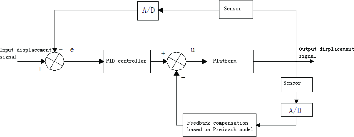
Block diagram of a double feedback PID control composited system
Footnotes
8. Acknowledgement
This research was supported in part by the National Science Foundation of China (grant no. 61128008) and the Macao Science and Technology Development Fund (grant no. 016/2008/A1).