
Abstract
Due to scale effects, microoperation, especially the releasing of microobjects, has been a long-standing challenge in micromanipulation applications. In this paper a micromanipulation method is presented based on dynamic adhesion control with compound vibration. This adhesion control technique employs inertia force to overcome adhesion force achieving 100% repeatability with releasing accuracy of 4± 0.5μm, which was experimentally quantified through the manipulation of 20–100μm polystyrene spheres under an optical microscope. The micromanipulation system consists of a microgripper and a piezoelectric ceramics module. The compound vibration comes from the electrostatic actuator and the piezoelectrically driven actuator. Surface and bulk micromachining technology is employed to fabricate the microgripper used in the system from a single crystal silicon wafer. Experimental results confirmed that this adhesion control technique is independent of substrate. Theoretical analyses were conducted to understand the picking up and releasing mechanism. Based on this preliminary study, the micromanipulation system proved to be an effective solution for active picking up and releasing of micromanipulation.
Keywords
1. Introduction
Micromanipulation and microassembly are important emerging techniques that serve as enabling techniques for a wide variety of applications in biological and biomedical research, as well as in the assembly of microelectromechanical systems (MEMS) and microelectronic devices [1][4]. With the development of miniaturization, decreasing the scale brings us to technological limits, such that it seems to be necessary to use the intrinsic properties of the considered scale. Among the challenges, a long-standing difficulty in the manipulation is the release of microobjects from the end-effector due to the adhesion forces at microscale. Scale effects cause adhesion forces including the Van der Waals force, electrostatic force and capillary force to dominate volumetric forces (e.g., gravity) [5].
Currently, there are two types of release methods in micromanipulation systems, passive release and active release. Passive release techniques mainly depend on the strong adhesion substrate. In consideration of adhesion and rolling resistance factors [6], an Au-coated substrate is used for both the picking up and releasing operation. Microspheres were rolled on the special substrate causing the fracture of the sphere-substrate interface and the sphere-tool interface, respectively. Similarly, fixing miniscule glass spheres on a sample table by an ultraviolet cure adhesive [7] has also been demonstrated. Commonalities of passive releasing techniques is their dependence on surface properties, time consuming natures and poor repeatability.
By contrast, active release methods intend to detach the microobject from the end-effector without touching the substrate. A commonly used method of active releasing is by the use of vacuum tools [8], [9] to create a pressure difference for picking up and releasing. However, miniaturization and accurate control of vacuum tools is difficult, and sometimes its use in a vacuum environment is limited. In [10], [11], freeze tweezers were used to pick up microobjects and thawing of the ice was used to release microobjects. The approach requires a complex end-effector and is limited to micromanipulation in an aqueous environment.
Micromanipulation systems with MEMS microgrippers [12], [13] have also been widely reported. As the key technology, these double-ended microgrippers could pick up the microobjects easily and provide a sufficient clamping force. However, it is difficult to achieve effective releasing of microobjects since there is adhesion force between the objects and one of the gripping arms. Some methods are used to reduce the adhesion force, for example, surface roughening of gripping arms [14], chemically coating gripping arms [15] and changing the surface characteristics [16]. Nevertheless, the effectiveness of gripping arm treatment for releasing is limited since the residual adhesion forces are still strong enough to keep the microobject adhered to a gripping arm. An active releasing strategy using an MEMS microgripper that integrates a plunging structure between two gripping arms is present in [17]. 7.5–10.9μm microspheres were picked and released easily.
Considering the operation strategy, one type of active releasing makes use of mechanical vibration [18], [19]. The vibration method takes advantage of the inertial effects of both the end-effector and the microobject to overcome adhesion forces. The landing radius of the released object has been calculated and simulated in [20], however, the accuracy of this single vibration has not been experimentally quantified.
In this paper, we present a micromanipulation system based on an active picking and releasing strategy by adhesion control with compound vibration. The operation tools consist of an MEMS microgripper and piezoelectric ceramics, as shown in Figure 1. The microgripper is actuated by an electrostatic actuator and fixed on the PZT. This strategy retains the advantage of double-ended tools for picking up microobjects. The compound vibration caused by the PZT and the microgripper arms is capable of placing a microobject, adhered to a gripping arm, at the desired destination on the substrate, enabling highly repeatable releasing with a high degree of accuracy. In addition, in order to improve the gripping performance, the microgripper arms integrate sidewall piezoresistive force sensors to sense the gripping force. Protective beams are designed to prevent the gripper arms being broken during operation. Finally, successful manipulation of 20–100μm microspheres under optical microscope for capturing and releasing are presented using this strategy.

The composite operational tool

Non-contact force on sphere after separation

Compound vibration method
2. Adhesion control of compound vibration
2.1. Dynamical effects in manipulation
The adhesion phenomena are mainly a result of intermolecular potentials, as expressed by Van der Waals forces. Capillarity and electrostatic are also environment dependent forces that contribute to the adhesion. For microscale objects, these forces have higher magnitudes than the gravitational force and they are mainly attractive. Nevertheless, they depend on the inverse square or cube of the distance between the surfaces, for example, for Van der Waals, and their influence becomes obvious in contact. A minimum amount of force is thus necessary to separate two mediums in contact. This force is commonly called pull-off. In the case of a sphere (radius Rb) on a planar surface, its expression is approximately given by the JKR (for the lower boundary) contact models [20]

where γbb is the adhesive energy between microobject and microobject.
The dynamic method mainly takes advantage of inertial effects[20]. Figure 2 shows the status of a microsphere after separation by the dynamical effects of using a single-arm. There are two Van der Waals forces on the sphere, one from the cantilever and one from the substrate as shown in Figure 2. Suppose Fp is the Van der Waals force from the cantilever, Fs is that from the substrate and Fg stands for the gravity. The dynamic model after separation is

where the positive direction of θ is defined to be clockwise.
By Equation (1) and (2) we can see that the larger angle θ (≤90°) is, the easier it is to achieve the release in x1 direction. Theoretically when θ=90°, the location of the microsphere changes to the beam side from the bottom of the beam.
In the actual gripping operation, the adhesive forces are more complex between the microsphere and the two end arms of microgripper, and the microsphere is usually adhered at the single end beam. The release schematic diagram of the two arms' vibration is shown in Figure 3. This method uses an MEMS microgripper and an actuator device driven by PZT. The actuator device mainly provides the vertical upward acceleration of microgripper to help the arms get rid of the microobject. The release of the microsphere is accomplished by combining the X-direction vibration and the Z-direction vibration. The arms of microgripper can not only vibrate vertically, but also horizontally in the gripping direction. In the release process, the microobject can be close to the substrate. This way the microscale force of the substrate could be used to achieve a more satisfactory release effect.
2.2. Adhesion control with compound vibration
Specifically, micromanipulations are the main subject of this work. That is, manipulating objects submillimetre in size and working with distances in the order of micrometres. In this paper, a general micromanipulation system is established using characteristic forces at the microscale. Dynamical modelling is thus achieved using this example where the main particularity is to illustrate the main characteristics of the problem. The aim is to pick up and release a stack of 10–50μm radius balls located on a substrate and to align them on the same substrate. To perform this manipulation by adhesion control, a microgripper is used. Indeed, dynamical modelling must allow us to study material combinations, and acceleration of the gripper for the capturing and the releasing.

Adhesive phenomenon result from adhesion force

Model of dynamic pick-up
The manipulation task concludes in picking up a sphere initially placed on a silicon wafer surface using a gripper and then placing it at a selected location on the same substrate. Sometimes, the multiple particles may adhere due to the role of adhesion force during the pick-up operation. Therefore, the pick-up micromanipulation of the target particle cannot be accomplished, as shown in Figure 4. Then, the capture is accomplished by taking advantage of the stronger gripping forces of the microgripper. In order to avoid adhesion of other balls, the vibration of microgripper is employed in the lifting stage as shown in Figure 5.
By writing dynamic equilibriums of all components of the system, a simplified dynamic model of pick-up can be obtained [22]:


mp, mb are respectively the masses of the gripper arms and the microobject, Fext is the external force applied to the arms.

Model of dynamic release. (a) Arms vibrate only, and (b) PZT vibrates only and (c) the model of compound vibration.
The object is then brought in contact with the substrate at the release location. To achieve the releasing, the adhesion between the end-effector and the object must be overbalanced. This can be accomplished by the compound vibration of the end-effector and the whole gripper to reduce the adhesion force. In the releasing stage, the microsphere keeps adhering to one gripping arm by adhesion forces. If the microsphere adhered to the left arm, with the vibration of the two arms, the microsphere travels non-directionally as shown in Figure 6 (a).
On the other hand, if the vibration of Z-direction is only applied, the microsphere is subject to gravitational force and the adhesion-force together. The direction of composite force is then lower left corner. Ultimately, the microsphere is released by the single arm, as shown in Figure 6 (b). Both of these two methods cannot guarantee accuracy of releasing. In order to achieve accurate releasing, compound vibration is considered. Those are the vibrations induced by piezoelectric ceramics in the Z-direction and the vibration of two arms in the XY plane. In order to take full advantage of substrate adhesion and get the best releasing results, the microspheres contact with the substrate in the releasing process.
Then, a simplified dynamic model of release along the X (or Z) axis can be obtained similar to formulae (2)-(4) [23]. Although increasing the vibration acceleration can achieve the pick-up or release operation, the exorbitant acceleration will increase the degree of non-directional movement of the microobjects and affect the steady pick-up and accurate release operation. Therefore, the minimum vibration acceleration is the key to the valid operation. The minimum acceleration of pick-up and release can be obtained by the simulation and computing. The relation curve of the minimum release acceleration and the diameters of polystyrene microsphere can be obtained and are shown in Figure 7. Suppose the microspheres are released on the silicon substrate.

The minimal acceleration of release vs. microsphere diameters
3. Simulation analysis of micromanipulation
3.1. Simulation of pick-up micromanipulation
For the above-mentioned pick-up model of micro manipulation, the dynamic specification of the microgripper in the pick-up operation can be determined by the simulation analysis. The polystyrene microobject and the silicon substrate are adopted to be analysed.
The pick-up model is established using the Simulink method. The goal of pick-up simulation is set to achieve the dynamic requirement of the microgripper, which can realize a successful pick-up manipulation.
The dynamic simulation analysis of the pick-up operation is considered only under the Van der Waals force firstly. The result of the manipulation appears on the curves showing the evolution of the three characteristic distances of the problem vs. time (D bs , D bp , D bb ). The capture is efficient when D bb increases and D bs =D0 (initial contact equilibrium distance). A time law is applied to the speed Yp′ of the end of the gripper. One of the initial conditions is the Z-direction velocity of the microgripper and assuming the initial velocity is 0.
In this case of simulation, the calculated values of pull-off forces are

The capture occurred in the approximation when

Suppose the microobject diameter is 50μm. We can get the Van der Waals force between the two microobjects or between microobject and beam. Figure 8 shows the relationship between distance and time. When the Hamaker constant between the substrate and the microobject is greater than the Hamaker constant between the two microobjects, Figure 8 (a) shows that the non-target microobject will not be adhered to the target microobject, and D bs is always equal to D0, therefore, the target microobject can be smoothly picked up in the operation. The silicon is used as the substrate material, Hbs>Hbb, therefore, the situation does not occur under the influence of Van der Waals force. If the non-target microobject is adhesive to the gripper, owing to the contact area between the microobject and the substrate being larger than the contact area between the microgripper and the microobject, the microobject can be smoothly picked up.
If the non-target microobject, target microobject and the microgripper arm have adhered together, to simplify the analysis, we adopt the maximum value of the Van der Waals forces' sum. Simulation is carried by changing the initial velocity (acceleration) condition of the Simulink model. Simulation analysed that the minimum acceleration value is 120m/s2 approximately in pick-up operation is shown in Figure 8 (b).

Feature distance and time curves in the effective pick-up operation. (a) Hbs>Hbb, No adhesion between two microobjects. (b) Target microobject adheres to the beam and non-target microobject.
Based on the above analysis, the simulation analysed that the minimum acceleration value is 160m/s2 approximately at pick-up operation considering the electrostatic force and capillary force.
3.2. Simulation of release micromanipulation
For the above-mentioned pick-up and release model of micromanipulation, the dynamic specification of the microgripper in the pick-up and release operation can be determined by the simulation analysis. The polystyrene microobject and the silicon substrate are adopted to be analysed.
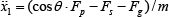
Change curves of feature distances D bp and D bs in the release process
From the pick-up model simulation we can see that the vibration velocity and acceleration of the microgripper played a decisive role in the pick-up process, therefore, we focus on the effect of the microgripper vibration in the analysis of the release process. In the release process, the vibration source in the X-direction applies the corresponding vibration frequency to reduce the adhesion force in the X-direction and to prevent microobject non-directional fly. The valid release condition is that Dbs=D0 and Dbp increases to the distance, outside which the microscale forces can be ignored. Figure 9 shows the change curves of feature distances Dbp and Dbs in the release process. Simulation results show that the minimum acceleration value is 180m/s2 approximately in valid release operation.
4. Design of the micromanipulation system
4.1. Configuration
The experimental setup consists of macro moving precise positioning stages, piezoelectric actuator, microgripper and microvision systems. The system can operate objects of a size ranging from 20μm to 100μm.
The composite operational tool is the key to the entire operating system. In order to make better use of inertial effects, an additional compound vibration is introduced with a vertical vibration and a horizontal vibration in plane. The theoretical analysis of the compound vibration will be presented in the third section. The vertical vibration is achieved by the PZT and the two microgripper arms vibrate relatively in the operation plane actuated by sinusoidal AC signal. The objects in the middle of two arms could be positioned effectively under the action of compound vibration.
4.2. Design of the microgripper
Figure 10 shows a schematic model of the microgripper. This typical microgripper consists of flexible beams, electrostatic comb fingers, force sensor beams (as the gripper arms), glass substrate and bonding pads.

Model of the microgripper
The end-effectors of the gripper are processed in a single standard silicon wafer (i.e., no silicon on insulator wafer is used), which realizes the miniaturized grippers with end-effectors on the size-scale of the manipulated objects. The electrostatic actuator generates a linear horizontal motion, which is converted into rotation of the arms by an S-type flexible beam system. The movable structure is supported by the flexible composite suspending beams. The substrate material is glass which can serve as an insulation function to the gripper. The integral dimension of the microgripper is 6.2 × 3.0 × 0.8mm. This gripper can operate objects of sizes ranging from 0 to 100μm.
Surface and bulk micromachining technology is used to fabricate microgrippers from silicon wafers. The fabrication sequence is illustrated in Figure 11.

Process sequence of microgripper fabrication
The starting material was 4-inch, N-type, (100) orientation, 1–10Ωcm double polished silicon wafer with a thickness of 300μm. The SiO2 layer thickness was controlled to be approximately 0.5μm, and then buffer HF acid etching SiO2 with photoresist as the etching mask. The piezoresistors were formed using the boron diffusion process. The contact holes are patterned by photolithography and opened by wet etching in a buffered HF solution. 1 μm-thick aluminium wires and bonding pads were formed by vacuum evaporation, photolithography and etching processes. The releasing windows on the reverse side of the wafer were patterned by photolithography. Then DRIE Bosch process was used to thin the device regions to 50μm with photoresist (AZ9260) as the etching mask. Then the glass wafer and silicon wafer were bonded together to form the support base. The glass becomes the nonconductor for the electrostatically driven fingers. With the patterned photoresist and SiO2 layer as the etching mask, the mechanical structure and the vertical sidewall surface are formed using DRIE. In order to ensure the identical dimension of each piezoresistor, the parameters of the DRIE should be strictly controlled.
The force sensor in the dynamic system occupied a secondary part, the detailed fabrication and use of the sensor can be found in [21]. The scanning electron microscope (SEM) images of the microgripper are shown in Figure 12 (a) and a photo of the microgripper is shown in Figure 12 (b).

Photos of the fabricated microgripper. (a) Microgripper in SEM. (b) Microgripper photo.
4.3. The piezoelectric actuator
The piezoelectric ceramic element is a component that transfers energy between electrical and mechanical states. Therefore, it can be used in different applications, e.g., the sensor, the actuator, etc. In this paper, the PZT driver is used to generate vibration acceleration and the PZT driver used is the same as that used in [21]. However, here it is used to generate vibration acceleration in the system not the gripper action.
5. Experimental results
A test setup was established to characterize the performances of the dynamic manipulation. This typical system consists of macro moving precise positioning stages, piezoelectric actuator, microgripper and microvision systems. A composite operational tool consisting of the PZT and microgripper was mounted on the positioning stages at a tilting angle of 30°. The test was carried out at room temperature of 20±3°C with relative humidity of 40 ±5%.
Aimed at microscale manipulation, the studies of steady pick-up, effective releasing and accurate positioning are experimented with under different environments and different sizes of microsamples. Through the summary of the factors in the micromanipulation, the initiative on microoperation to avoid microscale force interference is analysed and experimented upon. Figure 13 is the picture of the dynamic pick-up. The left picture shows the adhesion between the microspheres when the object was captured. To get rid of the interference of the other microsphere, an instant acceleration of capturing operation is applied as shown in the right picture, then the object is captured efficiently.

(a) Ball adheres to one arm and (b) PZT vibration used
In order to increase the hydrophobicity, a special process was carried out on the microgripper arms. They were modified with a self-assembled monolayer of FAS-17 (fluoro-alkyl silanes). The FAS-17 has good hydrophobicity. In addition, the surface of arms were also processed with rough treatment. These processes reduce adhesion significantly in the releasing process. The compound vibration effect is shown in Figure 14. As the model of rough surface coating is complex, it is not taken into account in the model of operation.
An experiment of releasing 40μm polystyrene microspheres with different sizes is performed with the system. Firstly, to characterize the releasing performance, single microspheres were repeatedly picked up and released from different heights (20–100μm) above the substrate. Figure 15 shows representative data of landing positions on the silicon substrate. The results show a relationship between landing positions and heights from the substrate, indicating that forces, including Van der Waals forces and electrostatic forces, from both the substrate and the microgripper, as well as the gravitational force, do not have a significant effect on the microsphere that travels a short distance in the air. The precision of landing is inversely proportional to the height from the substrate, partly due to the more pronounced airflow effect. Based on the corresponding theoretical analysis, the microspheres contact with the substrate in the releasing process in order to take full advantage of substrate adhesion and get the best releasing results.
(a) Microspere adheres to one arm and (b) compound vibration used

Landing positions of microspheres. h is the height of the gripping arms from above the substrate.
Combined with theoretical calculations and the actual situation, different vibration accelerations are programmed. PZT vibration acceleration is supplied from the PZT drive power and vibration acceleration of microgripper arms is supplied from the sinusoidal AC power.
According to peak acceleration formula a=4π2f2A, acceleration a and frequency f are proportional to the square. A small change of the frequency will make the acceleration value undergo greater change. The amplitude A has a linear relationship with acceleration and it is easily controlled. Therefore, in the experiments, we fix output frequency of the PZT and the gripper, and generate different vibration acceleration by increasing the amplitude of PZT and the gripper arms. In the experiments, two compound vibrations were applied to the instantaneous drive at the same time, the duration time is 100ms. Table 1 shows that the minimum acceleration corresponding to the different microspheres in the pick-up operation, in which the reliable amplitude value is the maximum amplitude value of each group result. Table 2 shows the average minimum acceleration corresponding to the different microspheres in the release operation.
The minimum acceleration corresponding to the different microspheres in the pick-up operation

The pick-up acceleration value is lower than the theoretical value and valid pick-up can be easily achieved. The success rates of the pick-up operation come up to 90%. The reason for this is that the pull-off forces calculated in the simulated analysis are of theoretical value. However, the practical impact of environmental factors and the substrate play a significant role in the experiment. The microscale force between the ball and substrate is larger than the theoretical values. Further studies are needed on this point.
The minimum acceleration corresponding to the different microspheres in the release operation

From Table 2, we can see that the minimum acceleration decreases with the increase of microobject diameter. The minimum acceleration value, obtained from the experiments, is lower than the theoretical value. Since the surface of the actual microgripper has a hydrophobic layer and small protrusions, designed to increase the roughness, these designs reduce the effect of the microscale forces. The results also prove that the compound vibration can effectively reduce the dynamic parameters and achieve a stable and accurate release effect.
Figure 16 shows the result of a series of microsphere releases. The releasing point range is calculated at a fixed coordinate system and we get an accuracy of 4 ± 0.5μm for microsphere release. In the figure the spheres of diameters 30, 45, 50, 80μm are arranged respectively. The cross-shaped arrangement is conducive to the calculation of position accuracy. The solid lines are the datum and the dotted line is the boundary region of release. The deviation between the lines can be calculated as the accuracy of release.

Stability of microsphere release experiments
6. Conclusions
In this paper a micro manipulation based on an active picking and releasing strategy by adhesion control with compound vibration is presented. This operation strategy employs inertia force to overcome adhesion force achieving 100% repeatability with releasing accuracy of 4± 0.5μm, which was experimentally quantified through the manipulation of 20–100μm polystyrene spheres. The piezoelectric actuator and the electrostatic force supply the mutual perpendicular vibrations which generate enough force to overcome the adhesion forces. The manipulation mode combined PZT and the microgripper which ensured the accuracy of the releasing operation. This paper revealed that the most important operating parameters are the vibration acceleration and the height from the substrate. With the experiments, the theory and practice experience is provided for the design of the micromanipulation system.
Footnotes
7. Acknowledgments
The authors gratefully acknowledge the contribution of the National Natural Science Foundation of China (no. 51105262, no. 61106110 and no. 51105263), and the Funds of State Key Laboratory of Transducer Technology, Chinese Academy of Sciences.