
Abstract
Compared with the traditional rigid mechanism, the flexible mechanism has more advantages, which play an important role in critical situations such as microsurgery, IC (integrated circuit) fabrication/detection, and some precision operating environment. Especially, there is an increasing need for 3-DOF (degrees-of-freedom) compliant translational micro-platform (CTMP) providing good performance characteristics with large motion range, low cross coupling, and high spatial density. Decoupled topology design of the CTMP can easily realize these merits without increasing the difficulty of controlling. This paper proposes a new three DOF compliant hybrid micromanipulator which have large range of motion up to 100 μm × 100 μm × 100 μm in the direction in the dimension of 90 mm × 90 mm × 50 mm, smaller cross-axis coupling (the max coupling only 2.5%) than the initial XY compliant platform in XY axial.
Introduction
The traditional rigid 3-DOF platform is usually assembled by a single-DOF platform with stepper motor driven, which composed of a fixed base and a motion stage translating along X-, Y-, and Z-axes in a plane. Compared with traditional rigid platform, compliant micro platform has become one of the main branches of the mechanisms and robotic systems due to their natural merits, such as reduced number of parts, no friction, and so on1,2 which make a CTMP more precise to have a variety of needs: cell manipulation,3,4 scanning probe nano-lithography,5,6 atomic force microscopy, 7 IC or targets fabrication,8,9 and data storage. 10 So a desired high precision CTMP should have the large motion range, minimal cross-axis coupling, without increasing the complexity of controlling.
Regarding a number of 3-DOF compliant micromanipulators, researchers pay a lot of efforts from theory to application. However, most of them based on the traditional rigid body model such as 3-RRR, 3-PRR, 3-PSS, or 3-PUU11–14 (P: Prismatic pair; R: Revolute pair; S: spherical hinge; U: Hooke vice), and rarely involves three translational micromanipulations.15–18 Xu and Li 14 presents the stiffness modeling of a three prismatic-universal-universal (3-PUU) compliant parallel manipulators with orthogonally mounted actuators, that is designed to provide three spatial translational DOF for nano-scale manipulation. Jensen et al. 19 introduces a three degree of freedom XYZ Micro-manipulator, which components on a platform using three legs, each composed of a slider mechanism and a parallelogram mechanism. Pinskier et al. 20 presented a modular flexure-based micro/nano manipulator, which has a measured range of translational motion of approximately 38.9 μm. Yangmin et al.13,21 proposed a novel 3-DOF complaint parallel mechanism for solving the conflict between large stroke and high precision of micro positioning platform which guarantees the requirement of large stroke and high resolution of the mechanism without a need for amplifier mechanisms. However, these compliant micromanipulators still have some shortcomings, such as small motion range, large coupling, complex structure, and non-pure translational motion.
In this paper, the main research contents include the design of the new XYZ CTMP, the analysis of the corresponding performance our and the physical control experiment based on the previous research. The remainder of this paper is organized as follows. Section 2 designs a new 3-DOF CTMP based on the 4-PP (prismatic joints) model. Section 3 shows the corresponding performance our of the 3-DOF CTMP by FEA. Section 4 shows the experimental results for verifying improved XYZ CTMP based on hysteresis compensation control strategy. The last part is the conclusion.
Micromanipulation design
Review of conceptual
The most XYZ micromanipulators are designed by the traditional rigid body model such as 3-RRR, 3-PRR, 3-PSS, or 3-PUU. And these models still have deficiencies such as cross-axis coupling motion and in-plane yaw motion. These deficiencies will affect the positioning accuracy of the flexible micro-motion platform, especially the precise operation process. Because the 4-PP model can more effectively eliminate the above problem, as shown in Figure 1, so it can be used in CTMP. P joints can be replaced by the parallelogram displacement amplifier, as shown in Figure 2, because of small space usage. So in order to obtain a novel XYZ translation flexible platform with smaller cross-axis coupling motion, it is necessary to design a flexible mechanism with symmetrical characteristics, which will be detailed in Section 2.2.
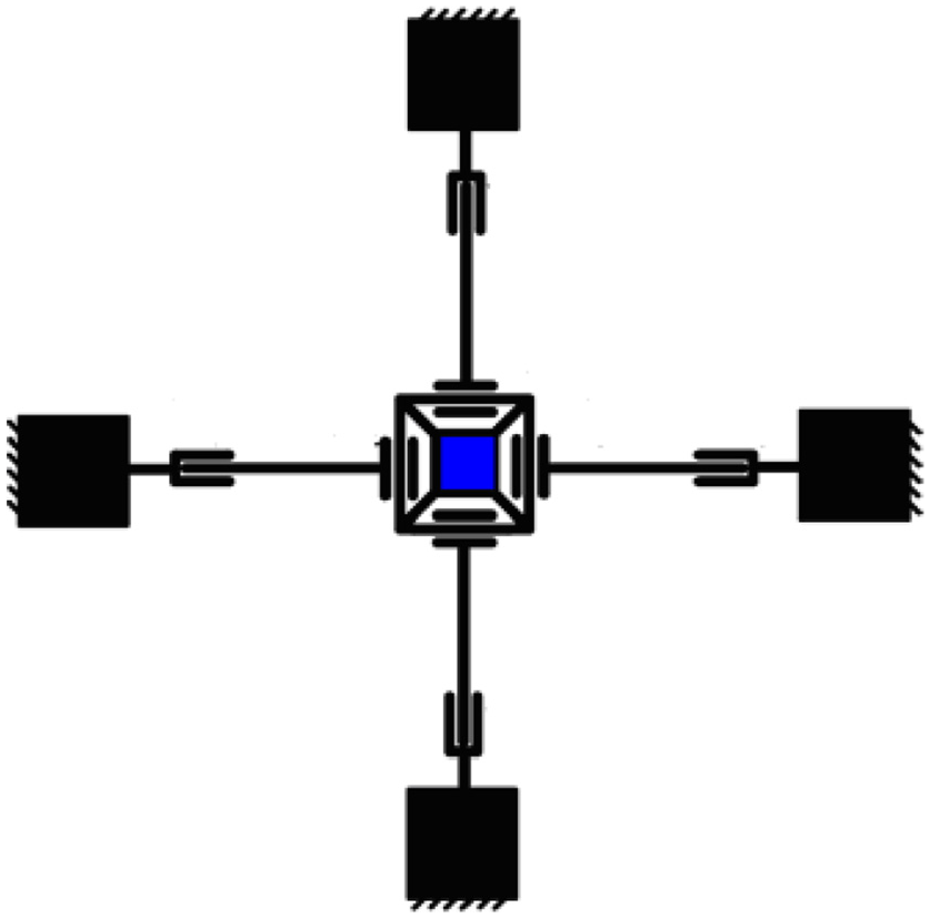
4-PP model.

The bridge displacement amplification mechanism.
Micromanipulation design
The computer-aided design (CAD) model of the proposed CTMP is shown in Figure 3 (XY CTMP is a part of my previous research. 22 Between the original XY CTMP and the proposed one, which have two main differences. The proposed structure can more effectively eliminate the cross-axis coupling motion and realize spatial motion of three degrees of freedom.), which has ten identical P structures with compliant amplifier structure, as shown in the red circle of Figure 3. There is a support plate between XY platform and Z axial, which are shown in Figures 4 and 5 respectively. In order to satisfy the output displacement of Z axial, and reducing the influence of the gravity of the XY platform, Z axial amplifier structure size is bigger than the XY platform amplifier structure size.

The CAD model of being proposed 3-DOF CTMP.

The XY platform model.

The support plate model.
Flexibility matrix
Because XY axial movement does not affect Z axial movement, and XY platform is a symmetric structure. We can only analyze the kinematic of X axial and Z axial.
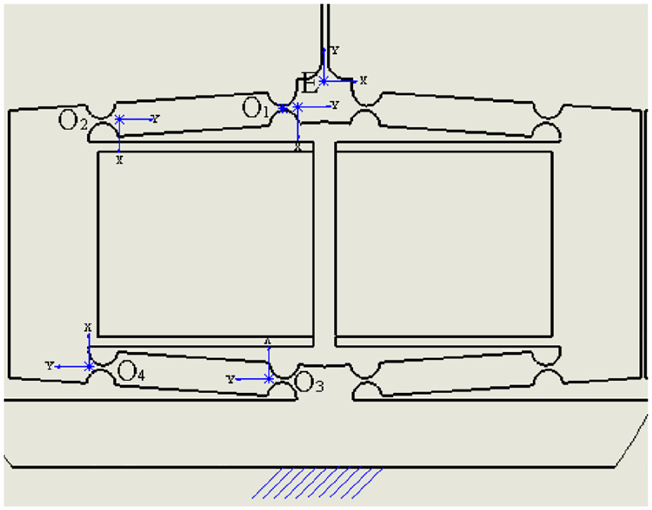
As shown in Figure 6, by the paper, 23 we know the circular flexure hinge equivalent flexibility:


A single circular hinge with two different coordinates.
If

Where E is the material elastic modulus; w is the width of the flexible structure; t is the thickness of the flexible structure; R is the radius of the circular, v is Poisson’s ratio, G = E/(2(1 + v)).
According to the transformation of force and displacement from the coordinate Oi to the coordinate Oj, the compliance of the free-end Oj with respect to the ground can be derived by:


In this paper, we only need to study hinge force and movement of three directions: X, Y axis force and linear displacement, around the Z axis of couple and angular displacement. For the transform matrix:
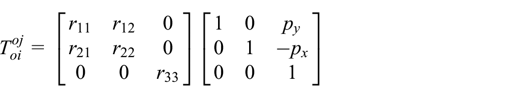
Where
The compliance models of the amplifier and parallel plate
Compared with the lever amplifying mechanism, the bridge amplifying mechanism has better performance. So the bridge amplifying mechanism is selected as the P hinge of CTMP, which is shown in Figure 7. Because of the symmetry of the bridge amplifier, the analysis process can be simplified. Taking the left half as an analysis object, the point E is connected to the fixed ground through hinges 1, 2 in series and hinges 3, 4 in series, the two branches are in parallel. The compliance of the left half part at point E can be derived by

The amplification mechanism.
In the same way, the compliance of the right half part at point E can be obtained:

Where
Because of the symmetry of the bridge amplifier, the compliance of the amplifier at point E can be derived by:

As shown in Figure 8, the compliance of the parallel plate 24 can be derived by:


The parallel plate.
Where E is the material elastic modulus; w is the width of the flexible structure; t is the thickness of the flexible structure; l is the length of linkage.
The output compliance model
As shown in Figure 4, the output compliance is defined as the compliance at the point O (the center of the moving platform), where the external force is exerted, is related to the ground. Because of the double symmetric property, we only select the limb down left for the purpose of compliance model analysis.

Accordingly, the compliances of limb left, right, and top can be derived. The output compliance of the XY stage can be calculated by:

In the same way, the output compliance of the Z stage can be calculated by:

Performance analysis
Material selection
The compliant micromanipulation based on the elastic deformation of the flexible hinge to achieve high precision movement, so the material mechanics performance requirements are higher.
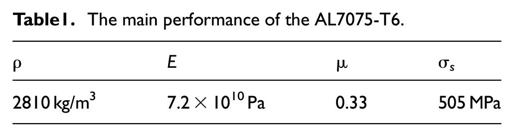
The material for the XYZ CTMP is chosen to be an aluminum alloy, AL7075-T6, due to the material’s high σ s /E ratio, low internal stresses, good strength, and long term phase stability, 25 which makes it suitable for precision engineering applications. 26 The attributes of this material are as follows Table 1.
The main performance of the AL7075-T6.
Strain and deformation
The strain and deformation results reflect the performance of compliance, sensitivity, linearity, and verify the motion of the proposed CTMP. 27 A set of selected piezoelectric linear actuators generate a representative force of 25 N on X axial of the mechanism in Figure 9. It can be observed that the maximal elastic strain with 2.37 × 10⁻⁴ mm/mm. Besides, the moving platform is the maximal deformation with 10.50 μm.

The piezo force is applied on X axial with 25 N: (a) total deformation and (b) elastic strain.
When three set of piezoelectric actuators are acted on X/Y/Z with 25 N force respectively, similarly with the preceding situation, the total deformation and elastic strain is illustrated in Figure 10. It can be found that the maximal elastic strain is 3.03 × 10⁻⁴ mm/mm. Besides, the moving platform is the maximal deformation with 16.96 μm.

The piezo force is applied on X/Y/Z axial with 25 N: (a) total deformation and (b) elastic strain.
It is shown that the X-axis load–displacement curves basically satisfy the linear relationship under the load condition A or B, a varied X-actuation range is over 0–100 N and a zero Y/Z-actuation (condition A) or a 25 N Y/Z-actuation (condition B), as shown in Figure 11. It can be seen that the load–displacement relationships for the CTMP can be regarded as linear under the two different load conditions. Based on finite element analysis, when the maximum output displacement (100 μm) is given in the direction of X/Y/Z, the maximum allowable stress of CTMP is 213 MPa, which less than the allowable stress of the material.

Load–displacement curves.
Cross-axis coupling
The output-displacement coupling error EX (the displacement fluctuation of motion stage along Y − (EXy) or Z − (EXz) axis caused by X-actuation), EZ (the displacement fluctuation of motion stage along X − (EZx) or Y − (EZy) axis caused by Z-actuation) is shown in Figure 12 reflecting the cross-axis decoupling. It can be seen that the maximum coupling error of the CTMP is −0.743 μm. We can calculate that the maximum compared with coupling error is 2.52% at EZx. It is slightly larger than that we expect (According to the preview research, 22 the cross-axis coupling of the initial XY compliant platform in XY axial is about 4.2%.). This may be mainly caused by the deformation or gravity of platform.
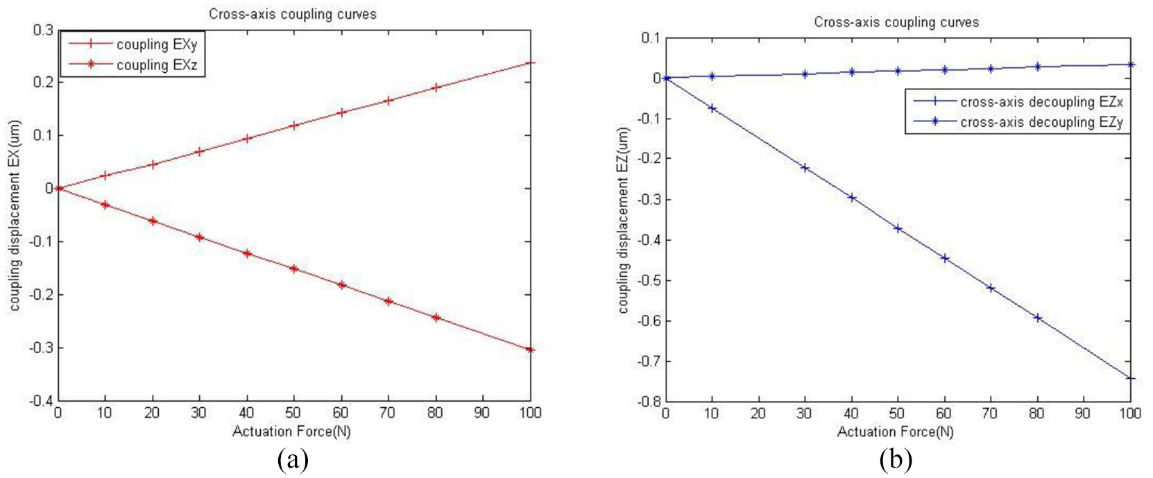
Cross-axis coupling: (a) the output-displacement coupling error EXand (b) the output-displacement coupling error EZ.
Experimental verification
Experimental scheme design
This system includes micro-platform, PZT, PZT driving power, capacitive displacement sensor, DC power, PCI6221, and PC, as shown in Figure 13. We know that the PZT actuator has instinctive complex nonlinear phenomena. So we designed a nonlinear control systems based on the EUPI controller to reduce the complex complex hysteresis phenomena (It’s the result of my previous research.). 28 The MATLAB simulink schematic is shown as in Figure 14.

The micro/nano-positioning system.

Simulink figure of the micro/nano positioning system. 27
Discussions of experimental results
As shown in Figure 14, when the PZT driver micro-positioning platform of nonlinear control systems added the step signal (Just consider the Z motion), so we completed the nonlinear composite closed-loop control to the platform, we can get the tracking performance and tracking error as shown in Figure 15, and we know that the system of the step signal average tracking error is only 1.43%.

The response of the stage for a step signal: (a) tracking result and (b) tracking error.
As shown in Figure 14, when the PZT driver micro-positioning platform of nonlinear control systems added a sine wave signal (

The response of the stage for a sine wave signal: (a) tracking result and (b) tracking error.
Conclusions
In this paper, an improved XYZ CTMP has been developed and tested. Compared between the original XY CTMP design and the improved design,we can found that the improved design have a higher degree of cross-axis decoupling with cross-axis coupling error (2.52%) less than the original XY CTMP (4.2%). Through nonlinear closed-loop control based on the EUPI controller, tracking error of XYZ CTMP is only 7.17%. The reason why the error is still large is that the filtering ability of capacitance displacement sensor is not enough. But the improved XYZ CTMP have convincing performance by FEA and experiment anslysis. It provides a reference for the research of micro-platform.
Footnotes
Handling Editor: James Baldwin
Declaration of conflicting interests
The author(s) declared no potential conflicts of interest with respect to the research, authorship, and/or publication of this article.
Funding
The author(s) disclosed receipt of the following financial support for the research, authorship, and/or publication of this article: This work was partially supported by the National Natural Science Foundation of China under Grant Nos. 61573093, U1613205, and U1731121, Shandong Province Key Research and Development Projects No. 2019GSF109105, and Doctoral Research Funding of BZU No. 2020Y32. The authors also thank sincerely the reviewers and editors for their very pertinent remarks that helped this article become clearer and more precise.