
Abstract
This paper builds the kinematic model of a wall-climbing caterpillar robot to reveal the validity and the benefits of the closed-chain kinematics of the four-linkage mechanism to a crawling gait. The caterpillar robot can climb on a vertical wall by coordinating the rotations of one active joint and three passive joints. The mechanical property of the closed-chain kinematics of the four-linkage model is analysed. Furthermore, the relation between the driving joint torque and joint angle in the wall-climbing process is deduced based on the coplanar arbitrary force system. Afterwards, the joint control method is discussed in order to coordinate the rotation of the four joints so as to realize a reasonable wall climbing gait. To testify to the availability of the closed-chain four-linkage model, a wall-climbing caterpillar robot is developed with three different adhesion modules based on the vibrating suction method. A successful wall-climbing test confirms both the practicality of the four-linkage model and the validity of the adhesion modules based on the vibrating suction method. The results also show the reasonableness of the driving joint selection rule for ensuring a safe and reliable wall-climbing procedure.
1. Introduction
A wall-climbing robot is a kind of special mobile robot which can move and work on a vertical wall for special tasks [1]. Although wall-climbing robots have been researched for many years, few practicable wall-climbing robots have been developed for performing very risky work. This is owing to two main difficulties in wall-climbing robot design: (1) the contradiction between the flexibility and weight. A light weight is the key consideration in a climbing robot design. However, high flexibility - which is often necessary for overcoming complex wall environments - normally results in a heavy climbing robot body; (2) the development of a simple mechanism with a high degree of freedom (DOF) as well as the available simple climbing gait [2]. A wall-climbing caterpillar robot based on a modular idea was proposed to address the above two difficulties [10]. The multi-joints mechanism endows the robot the high flexibility but a light weight. The modular wall-climbing caterpillar robot has a reconfigurable structure, higher flexibility and a lighter weight compared with traditional wall-climbing robots with multi-legs, a sliding frame and wheeled and chain-track kinematics.
So far, the ‘snake robot’ is most similar to the ‘caterpillar robot’ in terms of structure and motion gait. The first working snake robot was built by Professor S. Hirose at the Tokyo Institute of Technology in 1972 [3]. This robot was limited to planar motion but snake robots capable of 3-D motion have appeared more recently [4]. Together with the robots, mathematical models of both the kinematics and the dynamics of snake robots have also been developed. In 2008, a new snake robot which is capable of free planar obstacle avoidance and 3-D motion was developed by Transeth at the Norwegian University of Science and Technology (NTNU)/SINTEF Advanced Robotics Laboratory [5][6]. This robot is composed of several rigid joints which have two DOFs. Transeth developed mathematical models of the dynamics of the snake robot precisely on the theory of non-smooth dynamical systems. In 2001, the first snake robot in China is developed by five postgraduate students at the National University of Defence Technology. Afterwards, some dexterous snake robots were built at both the Shenyang Institute of Automations and Shanghai Jiaotong University [7]. Moreover, the detailed mathematical models of the kinematics and the dynamics have also been developed. Because the serpentine motion of the snake is more similar to the crawl of the caterpillar, the control method and the gait of the snake robot provide great and valuable references for the research of the wall-climbing caterpillar robot. However, due to the constraint induced by the suction cups which are attached on the wall, the wall-climbing caterpillar robot will be different from the snake robot in the following respects:
Difference in the locomotion driving force. The snake robot mainly creeps on the ground and its locomotion depends upon the friction between the body and the ground. Meanwhile, the wall-climbing caterpillar robot works on the vertical wall because its locomotion driving force comes from the fixed constraint - the caterpillar robot must attach on the wall. Furthermore, the requirements of the driving joints were greatly enhanced due to the gravity of the robot. The driving joints not only need to rotate precisely in accordance with the programmed algorithm, but they also need to compensate for the impact of internal force arising from the attached points of a closed-chain during the crawling procedure. Therefore, the robust driving joints become a basic condition for climbing a wall successfully.
Difference in the gaits and the control method. A snake robot can adopt many gaits to creep on the ground - such as serpentine, lateral rolling, sinus-lifting, etc. - while a caterpillar robot can only crawl in a vermicular motion. Snake robots can also adopt many control methods, such as the central pattern generator (CPG) method [8], obstacle-aided [5] and non-smooth dynamical systems [6], etc. However, these methods should be improved in order to take the fixed constraints on the attached points into consideration [9].
Difference in the mechanism. A wall-climbing caterpillar robot needs adhesion modules to adsorb on the vertical wall while a snake robot does not.
In summary, robust driving joints, the proper control method and reliable adhesion modules constitute three key points for a wall-climbing caterpillar robot in climbing on a wall safely and steadily. This paper develops a wall-climbing caterpillar robot prototype to fulfil these requirements. This paper is organized as follows. Section 2 provides an introduction for the four-linkage motional method (FMM). According to this method, the kinematical parameters of the passive joints can be determined by the rotation of one active joint. Afterwards, the mechanical property of the FMM is analysed in order to build the theoretical basis for selecting driving joints. The mechanical property simulation of FMM is also presented. In Section 3, a new caterpillar robot prototype based on the vibrating suction method is introduced. Since the principle of the vibrating suction method [10] is not the key research focus in this paper, only the mechanism of the adhesion module is discussed. Next, Section 4 analyses the locomotion gait. Finally, experimental validation is given in Section 5. The conclusions and suggestions for future work can be found in Section 6.
2. Mechanical Properties of Driving Joints
In previous research work [11], a simple caterpillar robot based on bionics was developed to study the mechanism's configuration and climbing gait. After a series of experiments, the mechanism configuration of the caterpillar robot was concluded, as shown in Fig. 1, and the climbing gait was confirmed, as shown in Fig. 2.

The mechanism configuration of the wall-climbing caterpillar robot [9]
The gait of a wall-climbing caterpillar robot
Although the mechanical configuration of the caterpillar robot very similar to that of a snake robot, the requirements for the driving joints are markedly different - the snake robot creeps on the ground. Thus, the forces applied to every joint only come from the adjacent links and more or less uniform distribution. For the caterpillar robot, its joints might endure more complex loads because of the gravity and the reaction forces from the attached points of the closed-chain [11]. It is necessary to analyse the mechanical property of the driving joints in order to choose a robust joint and ensure a successful wall climbing motion. This Section analyses how the joints rotate coordinately in order to allow the robot to climb onto the wall and also analyse how to select the driving joint.
2.1 Kinematics analysis of the FMM
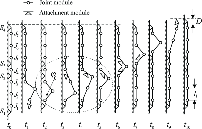
Fig. 2 depicts the gait of a wall-climbing caterpillar robot. λ is the step length, which is generated in one cycle motion. The caterpillar robot motion can be regarded as the multi-linkage movements.
The processes t0∼t1 and t9∼t10 are called the open-chain states, while the process t1∼t9 is the closed-chain state, during which there are 4 joints rotating simultaneously. The effect of the suction cups' deformation on the caterpillar robot is omitted so as to simplify the analysis, while the moving joints and links can be simplified as a four-linkage mechanism. There is only 1 DOF in the four-linkage mechanism, but 4 driving joints exist. To avoid the conflicts among these joints, one joint is appointed as the active joint and the other three joints will follow the change of the active joint in order to rotate. These joints are called the ‘passive joints’.
Process t3∼t5 will be analysed so as to deduce the kinematic relation between the active joint and the passive joints. There are two reasons for choosing process t3∼t5 as the research object:
The shape of the caterpillar robot at t4 is similar to those of t6∼t8 and can be considered as typical.
The caterpillar robot begins to change from the open-chain state to the closed-chain state at t3. All of the gravity of the robot is applied on the head suction cup and the tail suction cup. The internal force on the driving joints might be the maximum.
Fig. 3 (left) depicts an instantaneous state of the caterpillar robot during the process t3∼t5. The links (modules) of the robot are numbered 1∼8 from the bottom to the top and the rotating joints are labelled A, B, C and D. Let the inertial reference frame I={A, X, Y} attached to the joint A be as shown in Fig. 3 (right). Let AB=BC=CD=l and AD = l˜ = (1 + 2cosφ0)l, where φ0 is the initial angle as shown in Fig. 2 (t2). The angle from the link i to the positive Y-axis direction of I is denoted by φi (0°≤φi≤180°) and the sign of φi is determined by the left-hand rule. For example, φ3 is positive, φ4 is negative and φ5 is positive, as shown in Fig. 3. The following equation can be deduced according to the geometric relation of the links:

The instantaneous state of the caterpillar robot in process t3 ∼ t5

Let

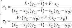
Where:


According to Eq. (1)∼(9), the kinematic parameters such as ω3, ω4, ω5, ε3,ε4 and ε5 can be deduced if φ3 is given. The kinematic parameters of joint B, joint C and joint D can be simply calculated by the angle functions of joint A when compiling the motion control program. Here, joint A is regarded as the active joint and joint B, joint C and joint D are regarded as passive joints. Joint B, joint C and joint D will be used as the active joint one by one for transferring the wave upward until it is transferred to the head of the caterpillar robot during the closed-chain state.
2.2 Mechanical analysis
The mechanical analysis presents the torque solution of the active joint. It is necessary to explain the concept of the proportional coefficient of the centre of gravity (ki) first of all. Every module of the caterpillar robot is simplified as a link with a fixed centre of gravity. Define the joint i as the joint between link i and link i+1. Let Li (i=1, 2,…, 8) be the length of every link and L i =l (i=2, 3,…, 7). Other parameters can be defined as the mass m, the centre of gravity Qi and the proportional coefficient of the centre of gravity ki. ki is defined as the ratio of the length between Qi and joint i-1 to Li, as shown in Fig. 4.

The schematic diagram of ki
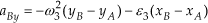
Fig. 5 depicts schematic diagram of the mechanical analysis in the instantaneous state in the process t3∼t5 whereby the earth-fixed frame is identical with frame I, as shown in Fig. 3.
Schematic diagram of the mechanical analysis
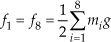
Let Lsuction be the height of the suction cup, f1 be the friction between link 1 (the tail suction cup) and the contact surface, f8 be the friction between link 8 (the head suction cup) and the contact surface, N 1 be the supporting force of the contact surface to link 1 (the tail suction cup), N8 be the supporting force of the contact surface to link 8 (the head suction cup) and Q(Qx, Qy) be the instantaneous centre of gravity of the caterpillar robot. Because the characteristics and contact states of both the head suction cup and the tail suction cup are all identical, the following equation can be obtained:
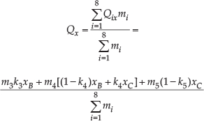
The centre of gravity can be obtained by the following equation:
Eq. (11) and Eq. (12) can be obtained by the equilibrium condition of the forces in Fig. 5:


Accordingly, N1 and N8 can be obtained according to Eq. (11) and Eq. (12):

2.3 Torque solution of the active joint
There is only 1 DOF in the four-linkage mechanism, while four driving joints rotate at the same time in the wall-climbing process. In order to reduce the inner forces arising from the redundant actuation, these four rotating joints should be defined as 1 active joint and 3 passive joints respectively. In this section, the state as shown in Fig. 5 will be analysed again, because this is a dangerous state in the wall-climbing gait and joint A maybe endure the maximum complex load from the other links of the caterpillar robot. Joint B, joint C and joint D are passive joints and they rotate by following the rotation of the active joint A. Therefore, joint B, joint C and joint D can be regarded as the hinges. This means there is no torque to produce in these 3 passive joints. The joints with no rotation (such as joint 1, joint 6 and joint 7) can be regarded as rigid connections. As a result, the instantaneous motion of the caterpillar robot is equivalent to the motion of a four-linkage mechanism.
Fig. 6 depicts the mechanical analysis of link 6, link 7 and link 8.

Mechanical analysis of link 6, link 7 and link 8
Eq. (14) and Eq. (15) can be obtained by the instantaneous equilibrium condition of forces:
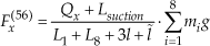

Fig. 7 depicts the mechanical analysis of link 5 (link CD, as shown in Fig. 5):

Mechanical analysis of link 5
Let joint D be the rotation axis. Eq. (16) and Eq. (17) can be obtained according to the theorem of inertia moment and the formula of centripetal force:

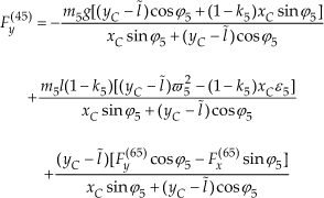
Fig. 8 depicts the mechanical analysis of link 4 (link BC, as shown in Fig. 5).
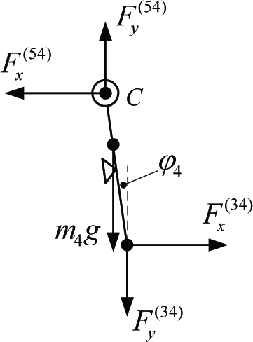
Mechanical analysis of link 4
Let joint C be the rotation axis. Eq. (18) and Eq. (19) can be obtained as well:

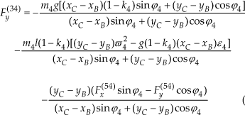
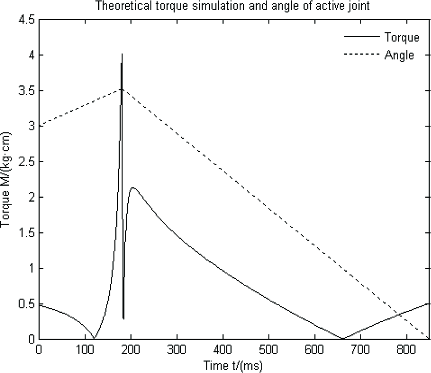
Fig. 9 depicts the mechanical analysis of link 3 (link AB, as shown in Fig. 5).
Mechanical analysis of link 3
Let joint A be the rotation axis. The theoretical active joint torque M can be obtained according to the theorem of inertia moment:

F*(jk) and F*(kj) are a pair of action and reaction forces in Eqs. (14)∼(20), where * of F*(jk) or F*(kj) denotes the X-axis or the Y-axis. The theoretical torque of the active joint can be calculated by Eq. (20). As a result, the proper driving joint can also be selected theoretically.
2.4 Torque simulation of the active joint
Because of the inevitable mechanical and control errors, Eq. (20) cannot be used directly for designing the caterpillar robot. Considering safety and reliability, the theoretical torque calculated by Eq. (20) must be multiplied by a safety factor to compensate for the mechanical and control errors. Therefore, the torque simulation of the active joint should be implemented before developing the caterpillar robot prototype.
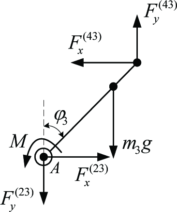
Because of mechanical and control errors, variable complex loads may be applied to the active joint during actual wall-climbing motion. Meanwhile, the variable complex loads are hard to calculate precisely, at present. It is necessary to multiply the theoretical torque, which is calculated by Eq. (20), by a proper safety factor. Fig. 10 depicts the theoretical torque simulation of the active joint.
Theoretical torque simulation of the active joint
The solid line shown in Fig. 10 denotes the theoretical torque simulation of the active joint A during the process t3∼ t5 (as shown in Fig. 2). The dashed line denotes the angle of joint A (φ3, the angle of link AB) changing with time. Let φ3 change with uniform angular velocity for simplification. φ3 changes with the following equation:

As Fig. 10 shows, a peak of the theoretical torque M occurred at t=181 ms. The reason for this is that φ3 changes its rotation direction, which leads to an infinite angular acceleration and an infinite theoretical driving torque. This situation will not arise during actual wall-climbing motion and only an instantaneous maximum driving torque can be found.
An additional statement should be announced: the curve of the theoretical torque M, as shown in Fig. 10, has already been revised a little. The peak value of M in the original simulation image can reach up to 7.86×10¹² kgcm, which is a 12th order of magnitude higher than the peak as shown in Fig. 10.
The maximum driving torque value is about 4 kg·cm, as shown in Fig. 10. The torque value is less than 2 kgcm most of the time. In order to ensure the safety of the wall-climbing motion, a quasi-safety factor should be not less than 3.5. Accordingly, the rated torque of the active driving joint should be not less than 14 kgcm.
A conclusion can be obtained from the analysis presented above: with the sufficient attaching forces produced by the head and tail suction cups and the precise angle controlled by 1 active joint and 3 passive joints, the caterpillar robot can perform the climbing gait shown in Fig. 2 according to the four-linkage mechanism. In Section 3, the working principle of the adhesion module will be discussed. The adsorption principle adopted in this caterpillar robot is different from that of traditional passive adsorption.
3. Development of the Caterpillar Robot
3.1 Mechanism of the caterpillar robot
The prototype of the wall-climbing caterpillar robot is shown in Fig. 11, whose total length is 750 mm while the total weight including the weight of the four controllers and the three batteries is 1.2 kg. The prototype consists of seven identical joint modules, which are interconnected together, each of them providing one rotation around the horizontal axis to the motion plane. The joint modules are driven by the standard servomotors.

Prototype of the wall-climbing caterpillar robot
The wall-climbing caterpillar robot also consists of four attachment modules which can attach to a flat wall by the suction cups, as shown individually in Fig. 12(b). The attachment module is developed based on the vibrating suction method [10]. Simply speaking, the process of the vibrating suction method is that an external force enforces the suction cup's vibration at a particular amplitude and frequency on a contact surface; then, a persistent negative air pressure can be generated in the suction cup and make the suction cup attach to the contact surface. The main advantage of the vibrating suction method is that it does not need a vacuum pump and a long tube to generate negative air pressure. Thus, it enables the mechanism of the wall-climbing robot to be compact and light. Because of the higher vacuum when compared with the traditional passive adsorption method, the attachment modules can attach to a rough surface.

Two kinds of modules of the caterpillar robot
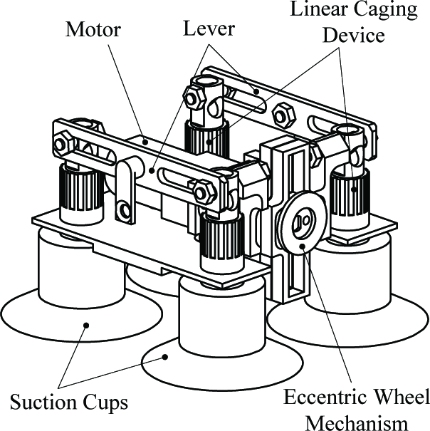
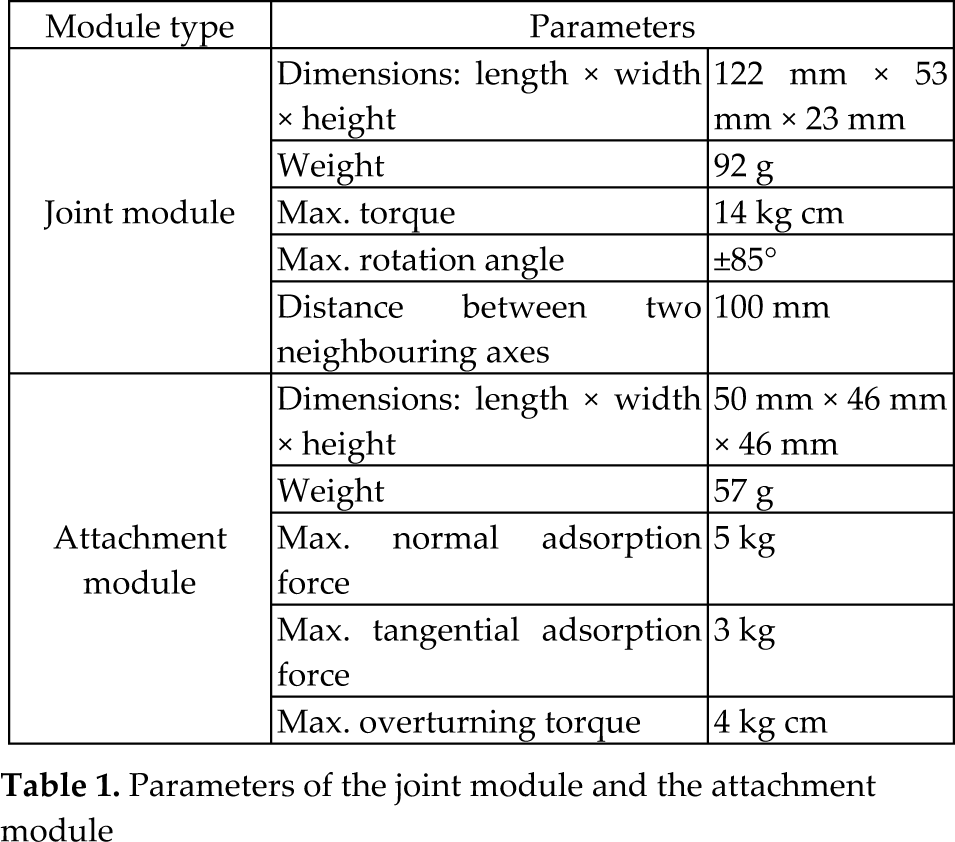
Fig. 13 shows the schematic diagram of attachment module. There are in total four suction cups, which are divided into two groups and driven by one eccentric wheel. When the eccentric wheel rotates, the rotational movement will be transferred into the vibrating movement of the suction cups by two levers. In each group, one suction cup goes up and another suction cup goes down. This means that the phase difference between the two suction cups in one group is 180 degrees. Fig. 14 shows the schematic diagram of the detachable mechanism, which makes use of the forward and reverse rotation characteristics of the motor. Combine the rotating motor with the eccentric wheel, we can see how the detachable mechanism works. When the motor rotates in one direction, the cams do not move, but the four suction cups vibrate. When the motor rotates in another direction, the cams will rotate with the motor. Although the four suction cups continue to vibrate, they cannot attach to the contact surface again. This is because the cams push the linear mobile link - as shown in Fig. 14 - to the left in order to make the vibrating suction cups open up to the atmosphere. Fig. 15 shows the realization of the inner mechanism of the attachment module with four vibrating cups. The parameters of the two modules are shown in Table 1.

Schematic diagram of the attachment module

Detachable mechanism
Realization of the inner mechanism of the attachment module
Parameters of the joint module and the attachment module
3.2 Hardware implementation
The control system of the caterpillar robot is shown in Fig. 16. The supervision unit for the control application consists of a PC running the MS Windows XP operating system. The desired joint positions as the robot's inputs are acquired beforehand and sent directly to the robot via the serial port interface.

The control system of the caterpillar robot
There are four controllers in total. Each controller can control one attachment module and two joint modules. Each controller consists of one ATmega16L type microcontroller. The controllers can communicate with each other via I2C-Bus.
The applied control algorithm is based on the angular position control of the joint modules. The mobile system is supposed to undergo exterior forcing due to the geometric constraints and the static friction operating between the attachment modules and its environment. Although the actual joint torque and frictional effects are highly unpredictable in such an application, the torques provided by the above mentioned servomotors are proven, experimentally, to be sufficient for the vermicular gait.
4 Analysis of the Locomotion Gait
4.1 A biologically-inspired wall-climbing gait
The wall-climbing gait applied for locomotion control is based on the natural vermicular motion observed in caterpillars. Experimental research on caterpillars exerting vermicular motion provides the following significant result: during the progressive motion, each section of the caterpillar body faithfully transfers the wave taken by the anterior section of the animal and the whole caterpillar body is observed as a moving wave from tail to head. In other words, the caterpillar controls the relative angular positions between its successive sections along the body. Fixed constraints will be formed once the prolegs attach to the contact surface. Hence, the animal translates its vermicular wave and maintains its overall geometric configuration with respect to the angle of the joint modular. It is known that caterpillars control the relative angular positions between their successive sections through contractions of their musculature system [13][14].
It is clear that the natural control mechanism observed in caterpillars can be translated into a problem of joint angle position control along the proposed artificial mechanism. Although several different wall-climbing gaits are available for the seven-joint modular caterpillar robot [14], a safest gait is adopted according to the vermicular motion of the natural caterpillar mentioned in Section 2. With this gait, the fewest joints are involved simultaneously, but the most suction cups are attached on the wall at any time. Fig. 2 depicts a whole cycle gait schematic of the caterpillar robot climbing on a vertical wall with a step length D. In Fig. 2, the joint modules and the attachment modules are denoted by Ji (i=1,2,…,7) and Si (i=1,2,3,4) respectively. In addition, l1 denotes the distance between the two adjacent joints.
From Fig. 2 we can see that there are four divided movements in the complete climbing gait. Firstly, between t0 and t2, the tail lifts up and bends and then puts down so as to generate an original step length (or wave). Secondly, the process t2∼t5 depicts the detail of how the joints' rotation corresponds to transfer the wave to the next section, as the dotted line shows. Thirdly, the process t5∼t8 depicts three repeated movements transferring the wave to the next section. Finally, the head lifts up and then puts down to change the wave into a real step length between t8 and t10.
According to Fig. 2, one step of the crawling gait of the caterpillar robot is composed of two open-chain states and a series of closed-chain states. Note that the processes t0∼t2 and t8∼t10 are open-chain motions, in which the head or tail suction cup can be controlled by three joints to move in a longitudinal plane with 3 DOF. During the open-chain motion process, a simple and effective control method - which called the unsymmetrical phase method [11] - can be adopted. Therefore, only the control rules in the closed-chain motion - from t2 to t8 in Fig. 2 - deserve further investigation.
4.2 Analysis of the closed-chain motion
There are four joints which rotate simultaneously at any time during the closed-chain motion period in order to transfer a triangular shaped wave from the bottom to the top. Here, the deformation of the suction cups is omitted for simplified analysis. To adapt to the fixed constraints between the attachment modules and the contact surface, the motion of both joints and the links of the trunk in instantaneous time can be simplified as a four-link kinematics model in order to calculate the joint angles. Actually, the wall-climbing gait also can be described as a procedure in which a wave is continuously transferred from one four-link model to an adjacent one (process t2 to t8 in Fig. 2). Moreover, the process t2 to t5 in Fig. 2 can be considered as a typical step.
There is only one DOF in the four-link kinematics model but all of the joints are active-driven. The four joint angles should be calculated according to the four-link kinematics so as to avoid inducing unexpected internal forces or redundant actuation between the links. We enlarged the dotted line in Fig. 2 for further analysis, as Fig. 17 shows. Fig. 17 depicts the detail of the four-link kinematics model, in which the four joints rotations corresponded to transfer the triangular wave upwards the distance of l1. As we can see from Fig. 17, the four-link kinematics model consists of four states and three processes. “State 1” represents a “Start” in which the joints just begin to rotate in the four-link kinematics model. “State 4” represents the joints as they stop rotating in the current four-link kinematics model and switch to the next “Start”. “State 2” and “State 3” are two middle states. In addition, each process denotes the intermediate corresponding rotation of the active joints from one state to the next.

Details of the four-link kinematics model
Because the joints are motorized, the angle of four joints should be calculated and rotated precisely in order to make the impact of internal forces or any redundant actuation between the links as small as possible. The first thing is to determine a “basic joint” whose trajectory will be deliberately specified and then calculate the angular values of the others based on the “basic joint”. “State 2” and “State 3” are not suitable for selecting the “basic joint”. Otherwise, the kinematical equations will be very complex. “State 1” and “State 4” can be regarded as the beginning and end of the four-linkage kinematics model. Moreover, “State 1” can change into “State 4” through “Process 1”, “Process 2” and “Process 3”. As such, “State 1” and “State 4” are suitable for selecting the “basic joint”. When the waveform passes away, joint 1 will change from the active rotation state into the leisure state until the next waveform arrives. Next, Joint 2 will change into the state joint 1 used to be in. Therefore, joint 1 is suitable to be the “basic joint” in Fig. 17.
When joint 1 is selected to be a “basic joint”, its trajectory can be deliberately specified. During time t 2 to t 5, the trajectory of joint 1 is expressed by a linear function for the purpose of simplification. The angle values of the other three joints can be calculated according to the value of joint 1 according to Eqs. (22) ∼ (24).
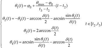


Where:

5. Experimental results
Based on the above analyses, a series of wall-climbing experiments are performed by the caterpillar robot. The caterpillar robot has successfully performed the proposed wall-climbing gait on a vertical glass wall, as shown in Fig. 18. The ti(i=0,…10) shown in Fig. 18 correspond to the ti(i=0,…10) shown in Fig. 2. The maximal step length D is 27 mm and the time of one step is 9s. At present, the robot is powered by 3 batteries and can climb on vertical glass continuously in a straight line until a “Stop” order is received. The maximum climbing distance reached was about 2.5 m, which is the limit of the length of the glass wall. The robot can move between surfaces in different planes, but only the flat surfaces are attachable because of the structure of the attachment modules. So far, the experiments have been performed only on a flat vertical surface. The locomotion between two surfaces will be the subject of future work.

One-step of the caterpillar robot on a glass wall
Although the four-linkage kinematics are taken into account, the internal forces between the links cannot be completely eliminated. The internal forces can be observed from the sharp change of the current consumption during one step, from 0.8 to 1.3 A. In fact, in a rigid over-actuated mechanism such as the closed-chain state of the proposed modular caterpillar robot, it is impossible to avoid the internal forces completely due to control errors and the clearance between parts. This shortcoming should be overcome in the future.
Because the vibrating suction method is adopted on the attachment modules, the caterpillar robot can also climb on a vertical rough wall, such as a wooden wall. Fig. 19 shows a series of experimental photos, in which the caterpillar robot climbs on a wooden wall. The validity of the vibrating suction method used on the caterpillar robot was verified by these wall-climbing experiments. The robot can climb on a rougher wall by adjusting the parameters of the vibrating suction device. Meanwhile, the robot can be expected to realize more complex locomotion on a vertical wall in the future.

One-step of the caterpillar robot on a wooden wall
6. Conclusions
The closed-chain kinematics of the four-linkage motional method were proposed according to the gait of the wall-climbing caterpillar robot.
The mathematical model FMM was built and the angle relation between the active joint and the passive joints was deduced. The rule for selecting driving joints was derived by analysing the mechanical property of the driving joints in FMM.
A wall-climbing caterpillar robot with vibrating suction modules was developed.
A series of wall-climbing tests were carried out and testified to the validity and the benefits of the FMM.
In future work, the research emphasis will focus on improving the control precision of the FMM, both in order to achieve error compensation for passive joints and for algorithm optimization. Another research point will look to how to reduce the unsteadiness of the base of the caterpillar robot arising from the vibration motion of the attachment modules.
Footnotes
7. Acknowledgements
This work is supported by the “National Natural Science Foundation of China” (No. 51075015).