
Abstract
Lower limb rehabilitation exoskeletons usually help patients walk based on fixed gait trajectories. However, it is not suitable for unilateral lower limb disorders. In this article, a hybrid training mode is proposed to be applied in rehabilitation for unilateral lower limb movement disorders. The hybrid training includes two modes, that is, the passive training mode and the active assist mode. At an early stage of the rehabilitation therapy, the passive training mode is utilized, in which microelectromechanical systems-based attitude and heading reference system is used to collect the gait trajectory of the healthy limb. The exoskeleton on the unhealthy limb will be driven to track the joint trajectory of the healthy limb. If the patient’s abilities recovered, the rehabilitation system can be switched to the active assist mode. Two force sensors are imbedded into the interface on the thigh to measure the interaction information in order to detect the patient’s initiative walking intention. In the active mode, the walking gait trajectory is modified and generated based on the gait trajectory of the healthy side via the attitude and heading reference system. In this article, a position close control loop is designed to drive the mechanical leg to help the unhealthy limb walk. Laboratory experiments are performed on a healthy human subject to illustrate the proposed approach. Experimental results show that the proposed method can be applied and extended in the passive and active rehabilitation mode for the unilateral lower limb disorders.
Introduction
Patients with various diseases and injuries, for example, spinal cord injury, stroke, and unilateral lower limb disorders have a dysfunction and impaired mobility in the lower limbs. It is a good way to conduct rehabilitation training to help these patients recover and regain mobility. 1 Intensive labor should be involved in the traditional rehabilitation training, and physical therapists have to provide the patients with highly repetitive training that is usually inefficient. 2 Therefore, it is necessary and impactful to develop assistive devices that utilize state-of-the-art technologies to help disabled people regain the ability to stand and walk, and release therapists from the heavy work of rehabilitation training. 3 Robotic exoskeletons for lower limb rehabilitation are developed for patients suffering from neurological disorders. 4 These robotic rehabilitation exoskeletons are aimed at helping patients’ lower limbs recover mobility. Compared with traditional manual assistance and training, they are able to perform as well as the physical therapists and free the physical therapists not to suffer from the onerous task and release therapists from the heavy work of rehabilitation training. 5 A robot-assisted rehabilitation system is required to follow some principles, for example, simple architecture and lightweight. Many types of rehabilitation exoskeletons have been studied and much progress has been made. Lower extremity rehabilitation exoskeletons can be divided into two categories according to their mechanisms and rehabilitation principles, that is, treadmill-based exoskeletons, for example, lower-extremity powered exokeleton 6 and active leg exoskeleton, 7 leg orthoses and exoskeletons, for example, knee–ankle–foot orthosis 8 and hybrid assistive limb, 9 foot plates-based end effector devices, for example, Haptic Walker, 10 and platform-based end effector robots, for example, ankle rehabilitation robot. 11
Leg orthoses and exoskeletons are anthropomorphic devices that perform similar movement with the human body and provide walk power assistance. Generally, the patient is able to regain the strength of limbs and recover from the injury gradually by different stages of rehabilitation training. The rehabilitation process can be divided into three stages, that is, the preliminary, intermediate, and advanced stages. 12,13 At the preliminary stage, passive mode is conducted to help patients reduce muscle atrophy and regain the movement ability to some extent by tracking the fixed trajectory. At the intermediate stage, the patient has gained certain degree of strength and is encouraged to try the robotic assistance with active efforts. At the advanced stages, the passive mode with predefined trajectory is not effective and pure active mode is designed to help the limbs walk according to the patient’s motion intention. The combination of gravity compensation, feed-forward movement assistance, and reinforcement of isometric joint torques is used to ensure that the patient can self-select walking speed. 14 In fact, this kind of method is based on fixed trajectory, which can adapt to different step length. For the robotic exoskeleton of assistance and rehabilitation, the control strategy can be divided into three kinds of methods according to the approach of the interaction signal, that is, control strategies based on biomedical signals, control strategies based on human robot interaction signals, and control strategies based on signals of mechanical system. 15 The rehabilitation exoskeleton, generally, is asked to follow the predefined gait trajectory and to response to predefined action based on gait pattern. 16
For the rehabilitation of unilateral lower limb disorders, traditional rehabilitation exoskeletons usually execute walk training by tracking the fixed gait trajectory. Since the healthy limb of unilateral lower limb disorders still has athletic ability and initiative motion intention, the single passive mode with fixed trajectory is difficult to adapt to usage requirements. 17 The fixed gait trajectory will cause interference with the initiative walking intention during the rehabilitation. The effectiveness of rehabilitation and therapy, indeed, depends on the ability of exoskeleton to help patients recover from the injury of disorders by the combination of rehabilitation stages. 18 In reality, the appropriate stage of rehabilitation and rehabilitation mode should be determined by the physiotherapist according to the diagnosis for the patient’s disability levels. For the patients with unilateral lower limb disorders, the healthy lower limb is capable of moving at natural speed and having natural gait trajectory. The functional compensation wearable exoskeletons are capable of improving the ability of the unhealthy legs or joints, for example, knee, ankle, and foot orthoses. 19 There are two kinds of exoskeleton structures for the rehabilitation of the unilateral lower limb disorders, that is, unilateral structure or bilateral structure. In this article, we develop a bilateral structure for the rehabilitation system. Those two freedoms, the hip and knee flexion and extension of the unhealthy side, are actuated by a disk-type direct current (DC) motor and an integrated actuation system, respectively. The healthy side has the similar mechanical structure, tightly connected around the lower limb. The mechanical limb should be parallel with the human limb and should be light and compact to avoid the discomfort of the human user. The mechanical limb is made of aluminum alloy and has the weight of 1.4 kg.
For the robotic rehabilitation system for the unilateral lower limb disorders, the measurement of the healthy limb movement is critical for the control of the unhealthy limb. The unhealthy side duplicates the movement of the healthy limb in the passive mode and adapts the gait trajectory online based on the interaction signals collected at the connection cuff using force sensors in the active mode. The gait trajectory of the healthy side can be obtained by some posture sensors, for example, inertial measurement unit (IMU), 20 and image-based devices, for example, Kinect. 21 The IMU, generally, has gyroscopes and accelerator or magnetometer and can detect the linear acceleration, angular velocity, and rotation angle. 22 The image-based method of detecting gait trajectory cannot be applied easily in the external environment. In this work, the robotic rehabilitation exoskeleton only moves in the sagittal plane and does not work at high speed. The human limb gait trajectory can be measured by microelectromechanical systems (MEMS)-based IMU sensors, which is light and compact. However, the time drifting problem cannot be avoided in the long term for the gyroscope sensors. To deal with it, in general, there are two kinds of methods, for example, extended Kalman filtering and the complementary filter. 23,24 In this article, a wearable lower limb exoskeleton is designed and developed for the unilateral lower limb disorders to regain the walking ability. A hybrid rehabilitation training mode is proposed to drive the mechanical leg. Gyroscope sensors are utilized to measure the angular position of joints, that is, the knee and hip joint, on the healthy leg. In the passive mode, the dyskinetic leg is acquired to follow the registered gait trajectory by the healthy side. In the active side, the gait trajectory will be generated again according to the force sensors information. The force sensors are applied to detect the active walking intention and regulate the gait trajectory for the dyskinetic leg based on the signals of gyroscopes. The primary goals of this article can be presented as the following: to improve the muscle strength by the passive mode and adapt to the initiative motion intention by the active mode.
The remainder of this article is organized as follows. The robotic rehabilitation system under studying is given in the second part. In the second section. The hybrid control scheme is developed in the third section. Experiments using the proposed approach and results analysis are presented in the fourth section. Conclusions are drawn in the final section.
Rehabilitation exoskeleton under studying
A limbs motion analysis
Lower extremity exoskeletons are the anthropomorphic devices that perform similar movement with the human body. A robotic exoskeleton system has the similar mechanical structure parallel with human limbs. The basic principles of exoskeleton design are expressed as follows: enough joint movement range, dexterous workspace, and lightweight. Generally, the robotic exoskeleton design is dependent on human motion analysis, that is, clinical gait analysis (CGA), which can give human limb joint angles, torques and powers for typical walking patterns, for example, level-ground walking. 25 Kinematic data of human limbs, for example, angular position, can be obtained via the three dimensional video capture system. Kinetic data of human joint, for example, actuating torque, can be acquired by applying dynamic models of human limbs. For a single leg of lower extremity exoskeleton, there are seven degrees of freedom (DOFs), that is, three at the hip joint, one at the knee, and three at the ankle. The hip joint moves in three different planes to form a spherical joint. 26 The hip joint has three DOFs, that is, flexion/extension in sagittal plane, abduction/adduction in coronal plane, and medial/lateral rotation in transverse plane. 27 The motion of flexion/extension is to advance the human body. The abduction DOF moves the lower limb away from the midline of the body, while the opposite occurs in adduction. The motion of medial/lateral rotation is rotating around the long axis of the femur. The knee has two major functions in sagittal plane, of which the first one is to cause an extensor moment to stand upright and the second one is to allow knee flexion to bring the foot off the ground. The knee joint can be flexed or extended. The ankle is a hinge-type synovial joint which has three DOFs of plantarflexion/dorsiflexion in sagittal plane, pronation/external rotation in coronal plane, and inversion/eversion in transverse plane. The ankle connects the leg segments of limbs to the foot to ensure the stability of standing. The movement range of human lower limb based on CGA is illustrated in Table 1. 26
Movement range of lower limb based on CGA.a

CGA: clinical gait analysis; DOF: degree of freedom.
aThe unit of the range of DOF is degree. The flexion/extension DOF of hip joint and knee joint is actuated.
The aim of the robotic rehabilitation exoskeleton system is to help regain the motion ability of the unilateral limb disorders. The flexion/extension DOFs of the hip and knee need larger power and torque, which are set as the active DOFs. The hip abduction/adduction and medial/lateral rotation are not important during a walking cycle. 28 Those two DOFs are passive and can move in a smaller range. In this robotic exoskeleton system, those DOFs of the ankle joint are passive with some elastic elements, since this exoskeleton, primarily, is to assist the leg segment.
Mechanical design
To keep the natural movement and achieve a comfortable walking, the DOF number of a lower extremity exoskeleton in the actual design should be close to the DOF number of human lower limbs. Based on CGA and real application, the lower extremity is designed as shown in Figure 1. Figure 1 shows that there are two active DOFs, that is, the flexion/extension in sagittal plane of hip joint and knee joint, respectively. We define that the left leg is the healthy leg and the right leg lacks athletic ability. To walk conveniently, the healthy leg wears the exoskeleton leg without any actuation system, that is, mechanical links. The hip joint on the unhealthy side is actuated by a DC motor system while the knee joint is driven by an integrated electrical actuation system. The integrated electrical actuator includes three main components, that is, a DC motor, a gear pair, and a ball screw, which is depicted in Figure 2. The usage of integrated electrical actuator can transfer rotation movement into linear one, which is beneficial for the placement of actuator without enlarging the size of mechanical legs. On the healthy side, there are two gyroscope sensors for the measurement of angular position of hip and knee joint, respectively. Since the actuation system is removed from the mechanism, the healthy leg can walk with the lightweight mechanical links easily. For the ease of wearing for users with different height, the exoskeleton system is designed to adapt to different users. The leg segment consists of a thigh and a shank with length adjustment mechanism, respectively. The exoskeleton system can be adjusted for the user in the range of 165–180 mm. The weight of a leg segment with the actuation system is 4.4 kg, while the other leg without actuation system is 1.4 kg. The whole robotic exoskeleton system, including legs, actuation system, control enclosure and the backpack, has the weight of 18.5 kg.

The prototype of the rehabilitation exoskeleton. We assume that the left leg is healthy while the right leg is unhealthy.
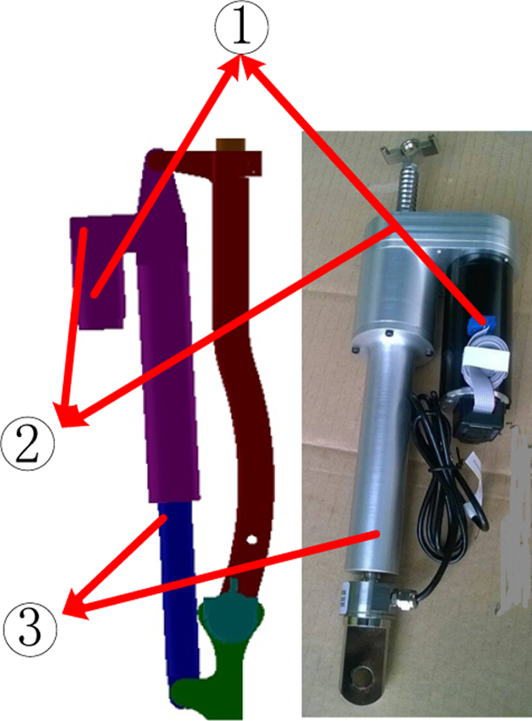
Integrated electrical actuator. 1: DC motor, 2: gear pair transmission, 3: ball screw with a slide nut. DC: direct current.
Hybrid training mode development
Control platform
A hybrid control mode is proposed for the rehabilitation training of the unilateral lower limb disorders. Since the patient has the walking ability on the healthy side, the passive mode should be used at the early stage of the rehabilitation and the active mode should be applied according to the recovery levels. The whole control hardware architecture is depicted in Figure 3. Basically, the control platform includes three levels, that is, (1) the high level, that is, a central PC, which executes algorithms developed by Visual Studio (VS9.0, Microsoft) and MATLAB (version 7.12, MathWorks) and send the computation results to the next level; (2) the middle level, that is, programmable multi-axis controller (PMAC; Delta Tau Corp, Chatsworth, California, USA) and the acquisition card, which are responsible for executing commands in real time and collecting signals from sensors and actuators; and (3) the low level, that is, real hardware, which is composed of sensors and actuation systems.

Control system architecture of the rehabilitation exoskeleton system. The whole control system have three levels, that is, high level, middle level and low level.
The PC has the interface to collect state signals and runs the corresponding algorithms, producing control signals for the mechanical prototype. The PMAC has four axes to receive commands from the PC and transfer them to drive the actuation system. In PMAC, those parameters used for motion programming are tuned and defined. The actuation system for the knee joint is an integrated electrical actuator, which is composed of a DC motor, a gear pair, and a ball screw. The DC motor is brushless and chosen from Maxon. The ball screw has a pitch of thread of 6 mm. The electrical actuator of the hip joint is placed on the rotation axis, which is composed of a DC motor and a gear transmission. The motor for the hip actuation has the power of 90 W, while that for the knee actuation has the power of 150 W. The specific parameters of the actuation system for those two joints are shown in the Table 2. The power of the system is provided by a lithium battery of 24 V. There are some DC converters to produce the power supplies of 5 V and 12 V. There are some safety precautions implemented on the exoskeleton system. In the mechanical design, physical status indicator switches are arranged to prevent leg segments from excessive excursions. The electrical system is equipped with two emergency shutoff switches, that is, an enable button that terminates the motor command signal, and a large e-stop button that shuts off the whole power.
Specific parameters of the actuation system of the hip joint and the knee joint.

There are four kinds of sensors utilized in the robotic exoskeleton system, that is, gyroscopes, foot pressure sensors, force sensors, and optical encoders. Foot pressure sensors are placed in the insole of the wearable shoes and can be utilized to identify walking phases. Gyroscopes, placed on the healthy limb, are applied to measure the angular position of the hip joint and the knee joint. One gyroscope is placed on the thigh for the hip joint and the other on the shank for the knee joint. Force sensors are utilized in the assistive motion mode to detect the initiative walking intention of the unhealthy limb. Two force sensors are placed in the interaction cuff on the mechanical leg, where one is fixed on the front and the other on the back, called human–robot interaction (HRI) signals. Actual joint angular position of the mechanical leg on the unhealthy side is measured by the optical encoders.
Kalman smoother for gyroscope signals
A MEMS-based attitude and heading reference system (AHRS) is utilized to measure the gait trajectory of the healthy limb. The AHRS includes gyroscopes, accelerators, and magnetometer and is capable of outputting three-axis rotation speed, acceleration, and posture (Roll, Pitch, and Yaw). The rotation angle can be obtained based on the integration of angle speed. The accuracy of measurement can be improved by the compensation of the information fusion algorithm, for example, extended Kalman filter. The AHRS in this article has a time drift of 4° h−1 for the rotation angle. To eliminate the time drift of the AHRS, the robotic rehabilitation system will recalibrate to set new reference point per half an hour. The utilized AHRS is shown in Figure 4 and its specific parameters are depicted in Table 3. The AHRS is small and can be fixed on the mechanical limb. The output of the AHRS can be transferred to the control computer through standard RS-232. The sampling frequency is 50 Hz and the baud rate is set as 115200. The angle of Roll is used for the measurement of the human limb gait trajectory.

Kalman filter and smoother for the gyroscope signal. The original signal is from the sensors directly. The Kalman smoother can smooth the signal’s trajectory and is capable of eliminating noises much.
Specific parameters of the AHRS.a

AHRS: attitude and heading reference system.
aThe accuracy is the dynamic accuracy.
The AHRS is placed on the mechanical leg on the healthy side to measure the human gait trajectory. The angular position of the healthy side is defined as θg(k) at the kth sampling interval. The registered angular position data is defined as the following

where θg,d(k) is the angular position relative to the initial position and θg(0) is the initial value of the gyroscope sensor. The initial value will be collected when the human limb stands straightly. The collected θg,d(k) should be filtered and smoothed to eliminate noises and construct the reference input of the unhealthy side. Kalman filter is applied to deal with signals measured by gyroscope sensors.
The Kalman filter has been one of the most often-used state estimation technique, for example, signal processing 29 and image processing. 30 The general state-space representation of a linear time-variant system is written in the following formula

where xk, yk, and Rk are the kth system state, the measured output value, and the measurement noise vector, respectively, uk−1 and Qk−1 represent the (k−1)th input to the system and system state noise vector, and A, B, and H denote the state matrix, the input matrix, and the output matrix. The updated equations for system and measurement are shown as follows 31

where Kk is the Kalman gain matrix, I is the unit matrix, and Pk is the variance matrix. We define uk−1 = 0 and

The xk represents the kth physical HRI signal at the kth interval and the time series of xk will be dealt using Kalman filter. All available measurement data together with the current data are used to deal with the measured data better. The Kalman smoother is able to smoothen the signal while eliminate noises. The smoothed distributions over the measurement can be calculated from the Kalman filter results by recursions as following 32

where
Strategy design
The hybrid rehabilitation strategy includes two modes, that is, the passive mode and the active mode, as shown in Figure 5. At the preliminary stage of rehabilitation, the exoskeleton system will be driven based on the angular position collected by the AHRS sensors. The angular position via AHRS sensors is regarded as the desired trajectory for the unhealthy limb. Optical encoders are used to obtain the actual angular position of the hip joint and the knee joint to construct a close position loop. The proportional–integral–derivative (PID)control law can be expressed as following

Hybrid control strategy for the rehabilitation exoskeleton system. The exoskeleton and the healthy limb are in the same integrated system. The gyroscope sensor is used to measure the angular position of the healthy limb and the optical encoder is utilized to feedback the actual position of joint.
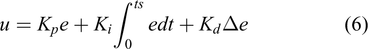
where θd(k) − θ(k), θd(k) is the desired gait trajectory, which equals to θg,d(k), θ(k) is the actual angular position measured by optical encoders, Kp, Ki, and Kd are parameters of the control strategy, which can be tuned in PMAC. In the passive mode, the primary goal of the mode is to drive the unhealthy side to follow the gait trajectory of the healthy side, measured by the AHRS.
When the unhealthy limb’ muscle has been strengthened, the active mode can be triggered. In the active mode, the gait trajectory is generated again on the basis of the measured gait of the healthy side. The mechanical legs connect with the human body via the interaction cuff and the wearable shoes. There are two force sensors placed on the front and back side of the interaction cuffs. The force sensor on the front can state that the leg should move forward continuously, that is, the legs move away from the body. Similarly, the force sensor on the back can declare that the leg should stop moving forward and reverse, that is, from the state of flexion or extension to the initial state. In this article, the force signals on the front and the back are defined as Ff and Fb. In this article, the assumption that the increment of angular position of the hip joint is same as that of the knee joint is stated. The modification of the gait trajectories can be obtained as the follows

where Δθd is the increment angular position, α and λ are constants, and kΔθ is the maximum increment relative to the maximum force kF. The gait trajectory will be modified and generated as follows

The modified gait θd,a(k) is the desired trajectory and the PID controller will drive the mechanical leg to shadow θd,a(k) to achieve active rehabilitation. The transition of those two modes can be performed by the user via pressing the trigger switch.
Experiments
Laboratory experiments are performed on a healthy wearer and ethical approval was granted by the Laboratory Management Council. The healthy wearer has the weight of 62 kg and height of 178 mm. The user is acquired to wear the robotic exoskeleton to walk on the level ground and stairs, as shown in Figure 6. Before the human subject walks by himself, he is asked to adapt the exoskeleton system with the safeguard. The user is able to choose the control mode, that is, passive mode or active mode. To evaluate the validity and effectiveness of the proposed control approach, our experiments will be classified into two cases, that is, the passive rehabilitation mode (case 1) and the active rehabilitation mode (case 2). In case 1, the user’s unhealthy side should follow the healthy side absolutely. In case 2, the user’s unhealthy side can regenerate the gait trajectory based on the physical HRI.

Experiments wearing the exoskeleton system.
Case 1: Passive rehabilitation mode
In the passive mode, the two AHRSs, placed on the thigh and shank, collect and preserve the gait trajectory of the healthy limb. The position control strategy is designed to drive the exoskeleton leg of the unhealthy limb to follow the preserved gait trajectory. To illustrate the experimental results, the x-axis is placed according to the walking gait cycle (%). The unhealthy limb should duplicate the movement of the healthy limb’s gait trajectory. Actually, the gait trajectories of those two legs have a phase difference. The experimental results are depicted in Figure 7. Figure 7(a) and (b) gives illustrations of the comparison of the healthy side and the unhealthy side for the hip joint and the knee joint, respectively. In Figure 7(a), the curve from the point “A” to the point “B” marked in solid line shows a walking gait cycle of the healthy limb. The curve from the point “B” to the point “C” is also a walking gait cycle of the unhealthy side. Those two curves are nearly the same while the gait trajectory of the unhealthy limb lags behind the healthy side for a walking cycle. As Figure 7(b), the curve from the point “B” to the point “C” of the unhealthy side responds to the curve from the point “A” to the point “B”. The curve of “BC” can match the curve of “AB” from the view of gait trajectory’s amplitude. Through the closed loop position control with tuned parameters, the unhealthy leg can follow the predefined gait of the healthy leg.

The gait trajectory of the healthy limb and gait tracking in the passive mode. The gait trajectory of the healthy side is collected by AHRS and that of the unhealthy limb is measured by encoders. This plot gives the corresponding gait trajectory of three gait cycles. AHRS: attitude and heading reference system.
Case 2: Active rehabilitation mode
In the active mode, the measured force sensors are used to modify the gait trajectory by equations (7) and (8) according to the walking intention of the unhealthy limb. As presented previously, these two sensors on the front and back side will determine that the leg should move forward or backward based on the predefined trajectory of the healthy side. Those two force sensors are placed in the connection cuff around the thigh. This kind of sensor has sampling frequency up to 500 Hz and output the voltage value of the interval [0, 10]. The modified gait trajectory can be calculated based on the output of the force sensor by equations (7) and (8), as shown in Figure 8. Figure 8(a) and (b) shows the gait trajectory of the knee joint and the hip joint on the unhealthy limb, respectively. Those legends “force,” “Unhealthy-passive,” and “Unhealthy-active” denote the physical HRI information, the gait trajectory without modification, and the gait trajectory with modification using the HRI signals, respectively. As shown in Figure 8(a) and (b), the HRI force on the curve from the point “A” to the point “B” is positive. As a result, the gait trajectory of the unhealthy limb in the active mode will increase based on that in the passive mode. Similarly, the negative HRI force on the curve from the point “B” to the point “C” causes the decrease in the gait trajectory.

Limb gait trajectory regeneration based on that of the healthy side in the active mode. The HRI force can be obtained by two force sensors. The trajectory of the “unhealthy active” is modified based on that of the “unhealthy passive” using the HRI force. HRI: human–robot interaction.
The gait trajectory of the healthy limb and that of the unhealthy side is compared in Figure 9. As shown in Figure 9(a), the trajectory from the point “A” to the point “B” denotes a walking cycle of the healthy limb. The curve from the point “B” to “C” represents the regenerated gait trajectory of the unhealthy side based the curve “AB.” The curve “BC” has a delay of a walking cycle compared with “AB”. Figure 9(b) illustrates the comparison of gait trajectory of the knee joint and the hip joint for those two limbs. The curve from the point “A” to the point “B” denotes the trajectory measured by the AHRS, while the curve from the point “C” to the point “D” represents the gait trajectory, which modified using the HRI force based on the gait trajectory of the healthy limb. The active mode is capable of improving the walking ability of the unhealthy limb based on the patient’s intention.

The gait trajectory comparison of the healthy limb and the unhealthy side in the active mode. The gait trajectory of the unhealthy limb does not duplicate the gait of the healthy limb but regenerate the gait trajectory of the unhealthy side based on the HRI force. HRI: human–robot interaction.
Conclusions
In this article, we contributed a hybrid rehabilitation strategy, that is, the passive mode and the active mode, for the lower extremity robotic exoskeleton. The walking gait of the healthy limb can be obtained by AHRS and the robotic exoskeleton will duplicate the gait trajectory in the passive mode or modify the gait trajectory in active mode to help strengthen the unhealthy limb. Laboratory experiments show and demonstrate that the proposed hybrid control strategy for rehabilitation is valid and effective.
In the future, some adaptive control strategy will be studied to compensate the uncertainties in the robotic system. In the active mode, the relationship between the increment of modified gait and the interaction force will be optimized to achieve that the active mode can adjust to different individuals.
Footnotes
Declaration of conflicting interests
The author(s) declared no potential conflicts of interest with respect to the research, authorship, and/or publication of this article.
Funding
The author(s) received no financial support for the research, authorship, and/or publication of this article.