
Abstract
A two-dimensional, seven link, nine degrees of freedom biped model was developed to investigate the dynamic characteristics of normal and transfemoral amputee locomotion during the entire gait cycle. The equations of motion were derived using the Lagrange method and the stance foot-ground contact was simulated using a five-point penetration model. The joint driving torques were obtained using forward dynamic optimization of the normal human gait and applied to the intact joints of the amputee. Three types of motion controllers; frictional, elastic and hydraulic were considered for the prosthetic joints of the amputee and their design parameters were optimized to achieve the closest kinematics to that of the normal gait. It was found that, if optimally designed, all three passive controllers could reasonably reproduce a normal kinematical pattern in the swing phase. However, the stance phase kinematics could only be replicated by the hydraulic and elastic controllers; the performance of the latter was highly sensitive to the design parameters. It was concluded that an appropriately designed hydraulic motion controller can provide reasonably normal kinematics and reliable stability for stance knee flexion prostheses.
1. Introduction
The normal human gait enjoys minimal energy expenditure and a consistent kinematical pattern, through coordinated movements of the lower extremities [1]. For amputees, to achieve an acceptable quality of life, there is a need for appropriately designed prosthetic legs that provide reliable stability during the stance phase and adequate control of motion during the swing phase of the gait cycle [2]. This would assure that the prosthesis could act as a substitute for the missing limb effectively, reproducing near to normal gait kinematics and kinetics with comfort and low energy expenditure.
In order to enhance the functional performance of the prosthetic legs, extensive research has been performed in robotics and prosthetics communities to develop improved designs for prosthetic joints and their motion controllers. The efficacy of these designs is often evaluated based on experimental examination [3, 7]. Such tests provide valuable information on kinematics, dynamics and energy costs of the amputee gait when using different prostheses. However, it is often difficult or even impossible to achieve general conclusions from experimental data due to the small number of test subjects available and the large inter-individual differences [6, 8]. An alternative approach is mathematical modelling, which can provide a better understanding of the role and significance of each individual design factor affecting the efficacy and performance of the prosthesis.
Several modelling studies of normal human locomotion have been reported in the literature with different levels of complexity, ranging from simple models with minimal degrees of freedom (DOF) [9] to highly sophisticated models with multiple joints actuated by muscle excitation [10, 11]. Previous modelling investigations of transfemoral amputee locomotion, however, have been few and were often limited to a single limb or a certain part of the gait cycle, e.g., the swing phase. Zarrugh et al. [12] simulated the swing phase dynamics of an amputee wearing an above knee prosthesis with a simple controlling unit. Mohan et al. [13] developed a mathematical model of an above knee prosthesis to study its function during the swing phase of the gait cycle and determine the optimal location of the prosthesis centre of mass. Bach et al. [14] also investigated the kinematic and dynamic characteristics of the swing phase of the transfemoral amputee gait using computer simulation techniques. Pejhan et al. [15] developed a simple mathematical model to study the influence of alteration of the prosthetic leg design parameters on the kinematics of the amputee gait during the swing phase. In a recent study, Suzuki [16] simulated transfemoral amputee locomotion during the swing phase using a musculoskeletal model and found the optimal knee joint friction that minimized energy expenditure.
The purpose of the present study is to develop a more comprehensive robotic model for the dynamic simulation of the entire gait cycle of transfemoral amputees wearing above-knee prostheses. A biped model with seven links and nine DOF was developed, including a foot-ground contact model for the stance leg. At first the normal human gait was simulated to obtain the joints' driving torques using forward dynamic optimization. Then, the actuators at the knee and ankle joints of one leg were replaced with passive motion controllers to simulate a unilateral amputee gait. Using this model, the performances of three different types of passive prosthetic knee controller mechanisms were investigated.
For each type of knee controller, the functional design parameters were optimized to achieve the closest kinematic pattern to that of a normal gait, when subjected to the normal driving torques at the intact joints. Also, the sensitivity of the amputee locomotion dynamics to the prosthetic design parameters was studied. The results were employed to compare the performance of the different motion controllers examined.
2. Methodology
2.1. Basic Model
A 2D robotic model of biped locomotion was developed to simulate the entire gait cycle, including the stance and swing phases, of a normal gait and of amputees. The model included seven rigid bodies, i.e., a HAT segment representing the head, arms and trunk and 6 segments representing the thighs, shanks and feet of the two legs (Figure 1(a)). These segments were considered to be connected via revolute joints at the hip, knee and ankle, resulting in a total of 9 DOFs.
The motion of the model was described using a coordinate system attached to the hip joint. Absolute angular coordinates, i.e., θ1 to θ7, were used to represent the orientation of the trunk, thigh, shank and foot of the stance leg, and the same segments of the swing leg, with respect to the vertical axis (Figure 1(b)). The two other DOFs of the model were represented by the position of the origin of the coordinate system. The dynamics of the model were formulated using the Lagrange method. The effect of muscles in producing the driving torques was represented using ideal torque generators at the relevant joints. For the prosthetic joints of the amputee, the actuators at the knee and ankle joints of one leg were replaced with passive motion controllers.
2.2. Foot-Ground Contact Model
The foot-ground contact of the stance leg was simulated using a penetration contact model (Figure 2). The vertical component of the foot ground contact force was formulated considering spring-damper elements attached perpendicularly to five contact points over the surface of a flat rigid ground:


The 7-link biped model of human gait.
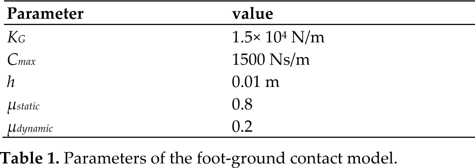
where Fn is the vertical component of the foot ground contact force and di and ḋi represent the ground penetration and penetration rate at ith contact points. Kg and Cg are the spring coefficient and damping coefficient of each element, respectively. We assumed the spring coefficient to be fixed (Table 1) and the damping coefficient to be a non-linear function of the ground penetration:
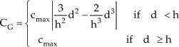
where cmax and h are constants obtained from the literature [17] (Table 1).
For the horizontal component of the foot ground contact force, we used a Coulomb friction model [18]:

where ẋ is the horizontal velocity of the contact point relative to the ground and μ is the coefficient of friction. The sgn(ẋ) term ensures that the friction force always acts in the opposite direction of the foot's motion relative to the ground. We used different coefficients of friction for static (ẋ < 0.05m/s) and dynamic (ẋ ≥ 0.05m/s) conditions. The constants of the foot-ground contact model were obtained from the literature [17, 18] and are illustrated in Table 1.
Parameters of the foot-ground contact model.
2.3. Normal Gait Simulation
The 7-segment, 9-DOF model from Section 2.1 and 2.2 was first used to simulate normal human locomotion. A forward dynamic optimization procedure was performed to find the joints' driving torques that best reproduced the normal gait kinematical pattern. The anthropometric properties of the body segments and the normal trajectories of the joints' flexion angles were adapted from the literature [19]. The torque generated by the ideal torque generator located at each joint was considered to be a function of the current tracking error from the reference trajectory:

where θri and
An optimization algorithm was employed to find the optimal values of the constant coefficients of Eq. (4), which minimized the tracking error from the reference trajectories (Figure 3). In each trial, the nonlinear equations of motion were solved numerically using the fourth order Runge-Kutta method. Then, in a pattern search optimization algorithm, based on the genetic optimization method, the simulation was run repeatedly to find the optimal values of the constant coefficients. Finally, the joints' driving torques that reproduced the normal trajectories with minimal tracking error were determined.
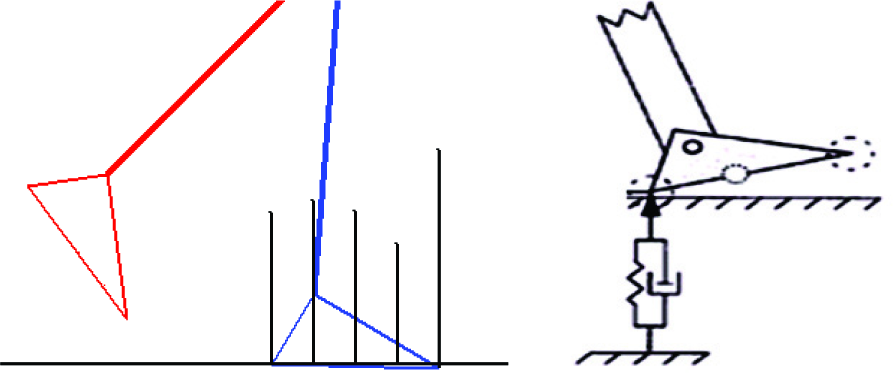
The foot-ground contact model including 5 contact points distributed over the ground surface (left) and a spring-damper system at each contact point to represent the vertical ground reaction force (right).

The optimization algorithm to minimize the trajectory tracking error and find the driving torques of the normal human gait.
2.4. Amputee Gait Simulation
The 7-segment, 9-DOF model from Section 2.1 and 2.2 was then used to simulate the locomotion of a unilateral amputee when wearing an above-knee prosthesis. The intact joints of the amputee were assumed to be subjected to the normal driving torques obtained in Section 2.3. The knee and ankle joints of the prosthetic leg, however, were considered to be equipped with passive motion controllers. Three types of passive controllers, i.e., friction, hydraulic and elastic, were examined for the prosthetic knee and a kinematics driver controller, i.e., a torsional spring-damper element, for the prosthetic ankle. An extension stop unit was also considered for the prosthetic knee to prevent hyperextension during the stance phase of the gait cycle.
Each of the three knee controller mechanisms was modelled independently and its governing equations were embedded into the main equations of the model. The friction knee controller was considered to produce a constant resistive moment against the knee flexion-extension motion. The elastic controller was represented by a linear spring and the hydraulic controller by a dashpot, which responded quadratically to the speed within the configuration of the DUPACO system [20]. The knee resistive moments produced by theses controllers were considered to be functions of the geometrical design parameters and functional design parameters, i.e., the spring constant and the damping coefficient, respectively, as described by Tsai et al. [20] and Pejhan et al. [15].
Following the formulation of the model for simulation of the amputee gait, the optimal values of the functional design parameters of the prosthetic knee controllers were sought so that kinematical patterns close to that of the normal gait could be achieved. The anthropometric properties of the body segments and the normal trajectories of the joints' flexion angles were adapted from the literature [19] and the driving torques of the intact joints were obtained from the simulation in Section 2.3. An iterative forward dynamic optimization procedure, based on the genetic optimization algorithm, was performed to minimize the tracking error. For each knee controller, two optimal functional design parameters were obtained for each of the stance and swing phases of the gait cycle.
A parametric study was also conducted to evaluate the sensitivity of the amputee locomotion dynamics to the functional design parameters of the prosthetic knee controllers. The functional design parameters of the friction, hydraulic and elastic knee controller, i.e., friction moment, damping coefficient and spring constant, respectively, were changed by ±25% and ±50% of their basic optimal values and the resulting changes in the gait pattern were investigated.
3. Results
The joints' driving torques of the normal human locomotion, obtained using the forward dynamic optimization procedure, are shown in Figure 4, in comparison with the data reported in the literature [19]. In general the pattern and magnitudes of the driving torques of the hip and ankle joints (Figure 4(a) and 4(c)) were in agreement with the reference data. However, the torque predicted by the model for the knee joint was considerably larger than what has been reported in the literature for a normal human gait [19], particularly during the stance phase (Fig 4 (b)).

The joints' driving torques obtained using the forward dynamic optimization procedure in comparison with the data from the literature [19]: (a) hip, (b) knee, (c) ankle.

Comparison of the results of the model for the normal human gait and the reference trajectory data indicating the angles of (a) HAT (b) hip, (c) knee, (d) ankle.

Stick figure illustration of the results of the normal human gait simulation.
These joints' driving torques were associated with very small tracking errors from the reference trajectories, i.e., the joints' flexion angles during normal human locomotion (Figure 5). This was particularly true for the HAT segment (Figure 5(a)) and the knee and ankle joints (Figure 5(c) and 5(d)). The largest tracking error observed was about 5° and was associated with the hip extension at the starting period of stance phase (Figure 5(b)). The stick figure illustration of the modelling results for the normal human locomotion (Figure 6) also shows a consistent kinematical pattern during successive gait cycles.
The results of the simulation of the amputee gait, based on the normal driving torques applied to the intact joints of the amputee and the optimal values of the functional design parameters of the prosthetic knee and ankle (Table 2), are illustrated in Figure 7. Results of the knee flexion pattern (Figure 7(a)) indicated a relatively good correlation between the prosthetic and normal kinematical data during the swing phase for all of the knee controllers examined. The largest difference from the reference data was observed for the friction controller with a maximum of about 6° deviation at 10° knee flexion. During the stance phase, the hydraulic controller was found to be capable of reproducing the normal knee kinematics with reasonable agreement. However, large discrepancies were observed for the elastic and, particularly, the friction knee controllers. The very large flexion angle found for the knee friction controller in the end period of the stance phase might be detrimental to amputee gait stability. Considering the entire gait cycle, the average deviation of the knee flexion angle from the reference data was 5.9° for the hydraulic controller, 11.6° for the elastic controller and 13.2° for the friction controller.
For the prosthetic ankle joint, again the results obtained for the three knee controllers in the stance phase were relatively similar to those of the normal gait kinematics (Figure 7(b)). During the stance phase, however, only the hydraulic and elastic knee controllers could reproduce the complicated pattern of normal ankle kinematics, which included a wavy dorsiflexion-plantarflexion motion. With the friction knee controller, the ankle plantarflexion continued towards the end of the stance phase. The resulting large plantarflexion angles could cause instability problems during amputee locomotion.
Optimal functional design parameters.

The results of the parametric study to evaluate the sensitivity of the amputee locomotion characteristics to the functional design parameters of the prosthetic knee controllers are illustrated in Figure 8. For all of the controllers examined, the effect of changing the design parameter was negligible during the swing phase. A different behaviour, however, was observed during the stance phase, particularly for the friction and elastic knee controllers. The change in the friction coefficient affected the flexion pattern of the prosthetic knee considerably during the second half of the stance phase (Figure 8(a)).
Increasing the friction coefficient caused higher knee flexion angles in this period, far from the normal data. It was found, however, that the decrease in the friction coefficient from its initial optimal value did not reduce the knee flexion angle to improve the kinematics towards a more normal behaviour.
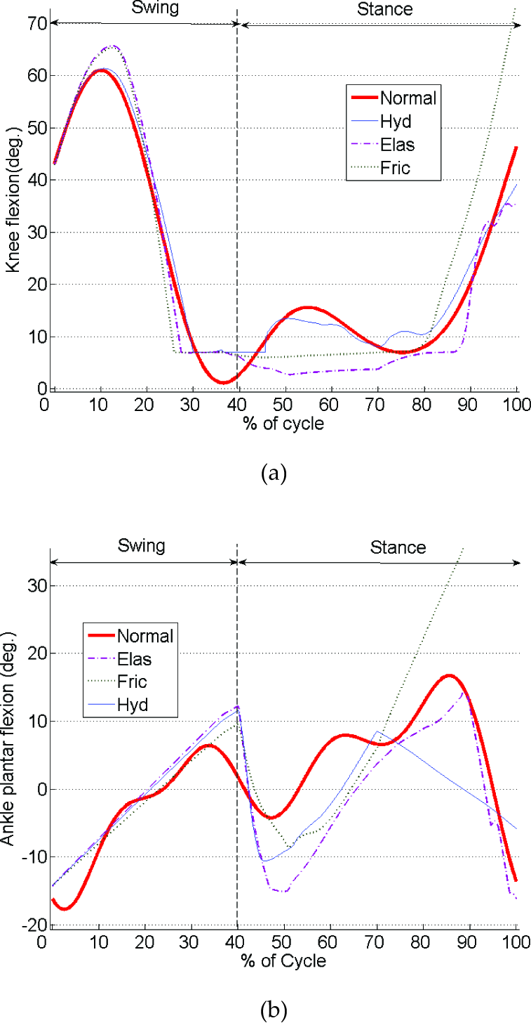
The flexion patterns of the prosthetic joints during the swing and stance phases of the gait cycle in comparison with those of the normal gait: (a) knee flexion, (b) ankle plantar flexion.
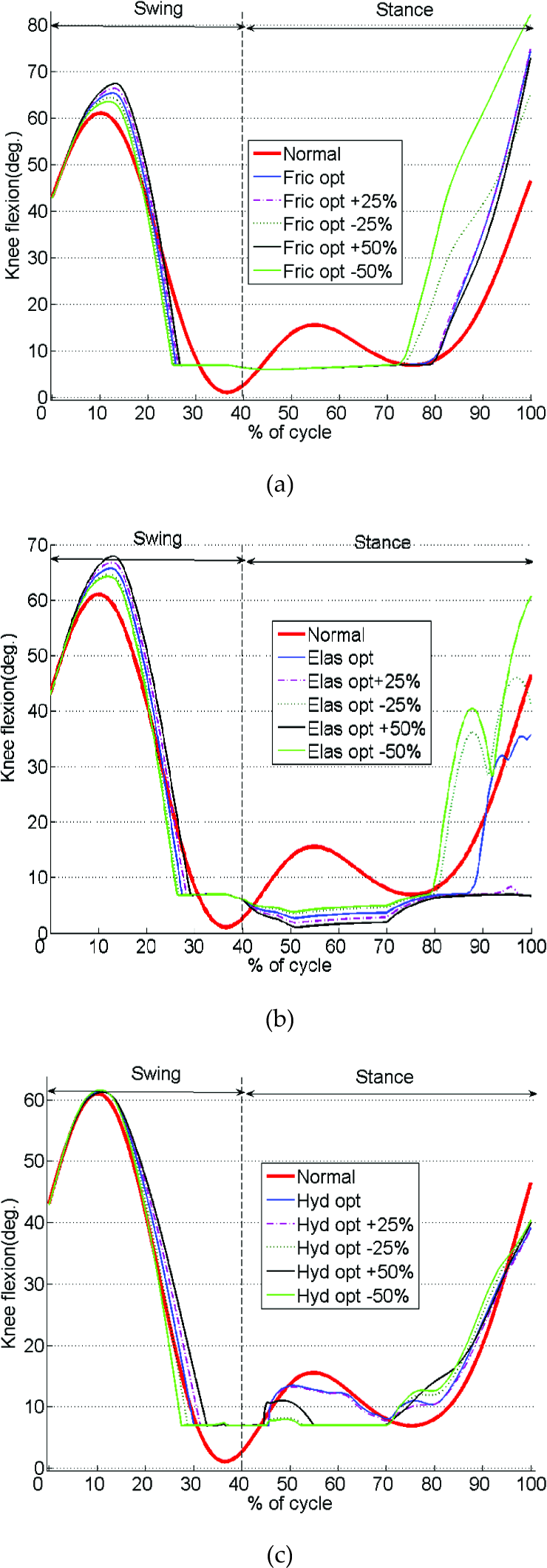
The effect of changing the controllers' design parameters on the flexion pattern of the prosthetic knee: (a) the friction moment of the friction controller, (b) the spring constant of the elastic controller, and (c) the damping coefficient of the hydraulic controller.
For the elastic knee controller the elastic constant was also found to considerably affect the prosthetic knee flexion pattern during the final third of the stance phase (Figure 8 (b)). With an increase and decrease in stiffness, much lower and relatively higher flexion angles, respectively, were obtained. In particular, decreasing the elastic constant caused a sudden change in the knee flexion pattern at the 90% instant of the gait cycle. This might cause instability and discomfort for the amputee due to the non-smoothed kinematical pattern.
The flexion pattern of the prosthetic knee with the hydraulic controller had the least sensitivity to the controller parameters. The change in the damping coefficient was found to have a relatively small effect on the prosthetic knee flexion during the first half of the stance phase (Figure 8 (c)). An increase in the damping coefficient caused a higher flexion angle in this part of the gait cycle. No considerable effect, however, was observed in the knee kinematics when the damping coefficient decreased from its initial optimal value.
4. Discussion
Studying the human gait dynamic characteristics through computer models can provide valuable information for a wide variety of applications including the design of lower limb prostheses. Pure experimental examinations cannot provide a deep understanding of the factors affecting the efficacy and performance of the prostheses. This is mainly due to their inadequate research methodology in view of the large variance in individuals who use a particular prosthesis and the small number of subjects available to participate in research. Computer modelling of the gait pattern, however, provides a detailed description of the role and significance of each individual relevant factor affecting the kinematics, dynamics and energy expenditure of the gait [21]. This is obviously of great importance in the interpretation of experimental data, which normally reflects the results of a combination of several determinants, e.g., the subject's condition, prosthetic design and gait pattern. However, the most attractive feature of computer modelling in gait biomechanics may be its capabilities for parametric studies.
The majority of recent investigations on the modelling of the transfemoral amputee gait have been almost exclusively dedicated to evaluating new prosthetic components and concepts to improve gait characteristics [22]. In particular, advanced microprocessor-based knee controllers have gained much attention [5-7, 23-25]. However, such systems are too expensive to be affordable for many amputees, particularly in developing countries [26]. Thus, it is still necessary and valuable to improve the design and performance of passive knee controller prostheses using experimental and modelling studies. An effective mathematical model of amputee locomotion needs to take into account the major characteristics of human gait, e.g., stability and transition between stance and swing phases. The 7-link biped model in the present study provides a more comprehensive and realistic simulation of prosthetic gait, in comparison with previous single limb and/or single-phase models [12, 16].
In the present study, robotic modelling techniques have been employed to investigate amputee locomotion in detail and analyse the effect of the prosthetic design parameters on the gait characteristics in search of designs with superior features. In particular, the aim of the study is that the prosthesis could reproduce the normal kinematics of the gait cycle when subjected to normal driving torques at the amputee's intact joints. This is consistent with the fact that transtibial and transfemoral amputees often adapt to prosthetic design perturbation primarily by maintaining the same kinematical pattern and adjusting their kinetics (joint torques). That is, they use a kinematics invariance strategy [27, 28]. A correlation between the normal kinematics and kinetics would assure that the joint loads are in the safe zone, not high enough to initiate destructive changes in the articular cartilage and not low enough to cause bone osteoporosis [29].
The effect of muscles in producing the driving torques was simulated in our model using ideal torque generators located at the joints. With an appropriate prescribed pattern of the net joint moments applied through these actuators one might expect the normal kinematical pattern of the human gait to be reproduced. However, we observed that if the actuators act as motion generators, which strictly exert the reference trajectories, the biped falls. This is thought to be due to relatively small, but functionally significant, errors in the displacement data obtained by the motion analysis systems that are commonly used for the simulation of gross human movements [30]. It has been shown that even small measurement errors might have disastrous effects on the ability of simulations to mimic the original kinematical pattern [31, 32]. Moreover, approximating the reference data by the Fourier series, in order to have a continuous and periodical mathematical function from the measured discrete results, can enlarge the errors of the reference trajectories. Thus, instead of using prescribed patterns of net joint moments for the actuators, we used a PD controlling algorithm (Eq. (4)) to adjust the torque generated by each actuator, so that the current tracking error from the reference trajectory is minimized. This ensures the kinematics of the model is close to that of the reference trajectory. For controlling the position of the whole biped with respect to the ground, however, an additional torsional spring/damper system needs to be incorporated in the model [32]. We considered such a system at the hip joint of the stance leg to produce a restorative moment proportional to both the angular deviation and the trunk angular velocity if the trunk deviated from the desired angle.
The results of the simulation of the normal gait cycle (Figs. 4, 5 and 6) indicated that the biped model in the present study could effectively reproduce the general characteristics of the human gait. The small deviations from the reference data are thought to be due to the model's simplifications. For instance, the foot was modelled as a rigid body and its interaction with the ground was simulated using a simple penetration contact model. Although an increased number of contact points, in comparison with previous studies [18], provided a more realistic representation of the foot-ground interaction, a more sophisticated flexible model is needed to obtain improved results.
The results of the simulation of the amputee gait (Figure 7) indicated that with all types of passive controllers examined, the prosthetic leg could reasonably reproduce the kinematics of the normal gait during the swing phase, under normal joint driving torques. In particular, improved results were obtained when the controller was designed based on the optimal design parameter (Figure 8). However, the sensitivity of the knee kinematical behaviour to the design parameter was not significant during the swing phase. Thus, even with a rough estimation of the controller unit design attributes, one can expect to obtain acceptable kinematical behaviour in the swing phase.
Generally, patients with transfemoral amputation do not use prostheses with stance phase knee flexion due to a feeling of instability. However, the results of our study suggest that close to normal stance phase kinematics can be obtained from hydraulic and elastic prostheses if the controller unit is designed appropriately. In particular, we found that the hydraulic controller provided a knee kinematical pattern highly correlated with that of a normal gait, with an optimal damping coefficient (Figure 7). For the elastic controller, the general pattern of normal knee flexion during the stance phase could also be reproduced (Figure 7 (a)). However, as our parametric study results indicate, unlike the hydraulic controller, which demonstrates minimal sensitivity to the design parameters (Figure 8 (c)), the performance of the elastic controller depends highly upon its design attributes (Figure 8 (b)). The superior performance of the prosthetic knee hydraulic controller, over other types of passive controllers found in our study, has also been suggested in previous experimental investigations [3, 33]. The constant friction moment controller appeared to be unable to reproduce the normal knee kinematics during the stance phase and is not recommended for prosthetic applications with stance phase knee flexion.
Our results for the kinematics of a prosthetic ankle (Figure 7 (b)) also suggest that the general pattern of normal gait kinematics could be achieved only using the hydraulic and elastic knee controllers. A detailed review of the results, however, reveals that even with such controllers the plantar flexion motion could not be reproduced to drive the stance leg at the push-off instant of the gait. This is obviously due to the passive characteristics of the prosthetic ankle joint considered in our study and cannot be improved by changing the design parameters.
In spite of the interesting findings discussed, care must be taken in making general conclusions from the results, in view of several limitations involved in the methodology of this study. First of all, we used a simple 2D robotic model with a limited number of links and DOFs to study the normal and amputee locomotion dynamics. With the advancement of this work to a more complicated 3D model, more detailed and reliable results could be achieved. Also, we assumed the anthropometric parameters for the prosthetics side to be identical for all types of the prostheses and similar to those of the intact side [34]. This is a simplification of reality that ignores the differences in the mass, centre of mass and moment of inertia in different prosthetic designs. Finally, the individual muscles were not included in our model and their resultant effect was represented by joint torque generators. Such a simplification is only a rough estimation of the muscular effort and cannot reflect the real behaviour of normal and amputee muscles during locomotion. Further work is currently underway to develop a more sophisticated 3D musculoskeletal model of the normal and amputee gait, so that a more accurate assessment of the prosthetic design parameters can be obtained.