
Abstract
A human–robot interactive control is proposed to govern the assistance provided by a lower limb exoskeleton robot to patients in the gait rehabilitation training. The rehabilitation training robot with two lower limb exoskeletons is driven by the pneumatic proportional servo system and has two rotational degrees of freedom of each lower limb. An adaptive admittance model is adopted considering its suitability for human–robot interaction. The adaptive law of the admittance parameters is designed with Sigmoid function and the reinforcement learning algorithm. Individualized admittance parameters suitable for patients are obtained by reinforcement learning. Experiments in passive and active rehabilitation training modes were carried out to verify the proposed control method. The passive rehabilitation training experimental results verify the effectiveness of the inner-loop position control strategy, which can meet the demands of gait tracking accuracy in rehabilitation training. The active rehabilitation training experimental results demonstrate that the personal adaption and active compliance are provided by the interactive controller in the robot-assistance for patients. The combined effects of flexibility of pneumatic actuators and compliance provided by the controller contribute to the training comfort, safety, and therapeutic outcome in the gait rehabilitation.
Keywords
Introduction
Robot-assisted gait rehabilitation solutions, as therapeutic adjuncts to facilitate clinical practice, have been demonstrated the effectiveness for patients suffering from neurological impairments such as stroke and spinal cord injuries. 1 –3 Gait rehabilitation training robots can be grouped as end-effector driven and joint driven robots according to their mechanisms. 4 For the end-effector driven robots (e.g. Gait Trainer, 5 Haptic Walker, 6 and LokoHelp 7 ), only the patient’s soles are fixed to and guided by the robot’s foot plates. Joint driven type (e.g. Lokomat, 8 Lower extremity powered exoskeleton (LOPES), 9 Active leg exoskeleton (ALEX), 10 Hybrid assistive limb (HAL), 11 and Lower extremity rehabilitation robot (LERR) 12 ) has leg joints that match those of the patient’s legs. Actuators are placed at the joints of the robot control joint motions to mimic normal walking patterns, providing the synchronized movement for the lower extremity joints of patients. Therefore, the wearable robot of multi-joint driven type is most suitable for patients in the gait rehabilitation training because of the physical coupling between them. However, there exist motion coupling and interaction between exoskeleton mechanism and human lower limbs. The wearer and exoskeleton form a closed loop as a human–robot cooperation system. Human–robot coordination is no longer a master–slaver relationship but a partnership of mutual perception and cooperation. Subsequently, the control strategy for the cooperation system develops from trajectory tracking control to interactive control, such as compliant control, patient-cooperative control, assist-as-needed (AAN). 13 Interactive control based on perceiving patients’ motion awareness is a hot and difficult research topic of rehabilitation training robots.
Literature has suggested that patients should be encouraged to participate actively and the role of rehabilitation robots should be to only scaffold or support when it is required for an effective treatment. 14,15 From this point of view, interactive control suggests that the robots only supply as much effort as a patient needs to accomplish rehabilitation training tasks by assessing his or her performance in real-time 16,17 ; whereas, trajectory tracking control is primarily used for early stage rehabilitation when patients have very weak muscle strength.
Assistance from robot is expected to be intelligently adjusted according to the patients’ physical conditions and efforts in rehabilitation, so as to encourage their voluntary participation. There is energy transfer between patients and rehabilitation robots in the interactive system, which is represented by the dynamic coordination of position and force. Three groups of interactive control schemes are widely used. They are hybrid force–position control, impedance control, and admittance control. 18 Hybrid force–position control takes into consideration the joint trajectories and interaction forces between the wearer and exoskeleton. It splits the task space into two complementary subspaces using a selection matrix. A position control strategy is implemented in one of subspaces and a force control in the other. For example, in the control of the ALEX, 10,19 the interaction forces between the wearer and ALEX are measured through two force/torque sensors mounted at the thigh and shank. The basic idea of impedance control is to regulate the dynamic relation between the wearer and exoskeleton by relating the position error (e.g. joint angles) to the interaction force/torque through mechanical impedance. For instance, in the control of Lokomat, 20,21 the outer-loop is composed of position feedback and the inner-loop is of force feedback. The adjustable range of the reference trajectory is established according to the patient’s joint angle information. Correcting force/torque is generated by the angle error by impedance algorithm for the robot. The stiffness parameter K in the impedance algorithm is changeable to provide the robot with adjustable assist torque to realize the ANN control. Xiong et al. 22 propose a hierarchical structure of the control system. It allows the execution of sequence of switching control methods: position, force, force/position, and impedance. Force/position control is used to deal with both instant and sustaining spasms of patients for safety. Impedance control is employed in human–robot interactions to help the patient achieve functional movements with torque just as much as needed. In brief, for the impedance algorithm, human–robot interaction information is used for inner-loop control, while the outer-loop is position control, so ultimately the patient adapts to the predefined trajectory of the robot rather than the robot following the patient. In active rehabilitation training, another emphasis is placed on the robot providing a certain amount of damping but following patients, providing safe and compliant interactive control, and so scholars put forward admittance control. The admittance controller takes an interaction force as input and reacts with a displacement. The human–robot interaction force transforms into the modification of the desired trajectory to track the patient’s motion intention. For example, Zhang et al. 23 developed a compliant ankle rehabilitation robot (CARR) actuated by four Festo Fluidic muscles (FFM) with admittance controller in task space. The adaptation law is proposed to change the admittance parameters based on real-time ankle posture and interaction torque. It adaptively modifies the predefined trajectory by the admittance controller to ensure training safety by avoiding excessive interaction force. Liu et al. 24 proposed a control algorithm that used the admittance characteristics between the force and velocity to realize the coordinated swing movement of the wearer and lower limb exoskeleton robot driven by hydraulic cylinders. Research shows that admittance control can effectively reduce interaction force by identifying the wearer’s motional intention and realize human–robot coordination of rehabilitation training or assisted walking. Human–robot interaction in the course of work is a time-varying dynamic process, fixed controller parameters cannot reach the actual need of dynamic interaction, so the research focus in recent years is mainly on how to effectively adjust the parameters, that is, adaptive impedance or adaptive admittance control strategy.
A new adaptation law is proposed in this study. Reinforcement learning is introduced into the parameters adjusting process. Based on the learning algorithm, an admittance model including patient’s personal characteristics is established for the interactive control in active rehabilitation training. Our group developed a pneumatic wearable lower limb exoskeleton robot. Pneumatic actuators provide a certain degree of passive compliance, while the proposed admittance control algorithm based on reinforcement learning provides active compliance by adapting robot behavior to patients. The combined effects of flexibility of actuators and compliance of control can improve the training comfort, safety, and therapeutic outcome in the gait rehabilitation. The robot is capable of providing assistance at low compliance level to severely impaired subjects and can adapt the compliance to an increased level for subjects with less severe impairments.
Pneumatic driven gait rehabilitation training robot and force/position detection
The gait rehabilitation training robot consists of a weight-reducing suspension device, a weight support mechanism, a hip adjustment mechanism, two exoskeletons of lower-limb, and a treadmill, 25 as shown in Figure 1(a).
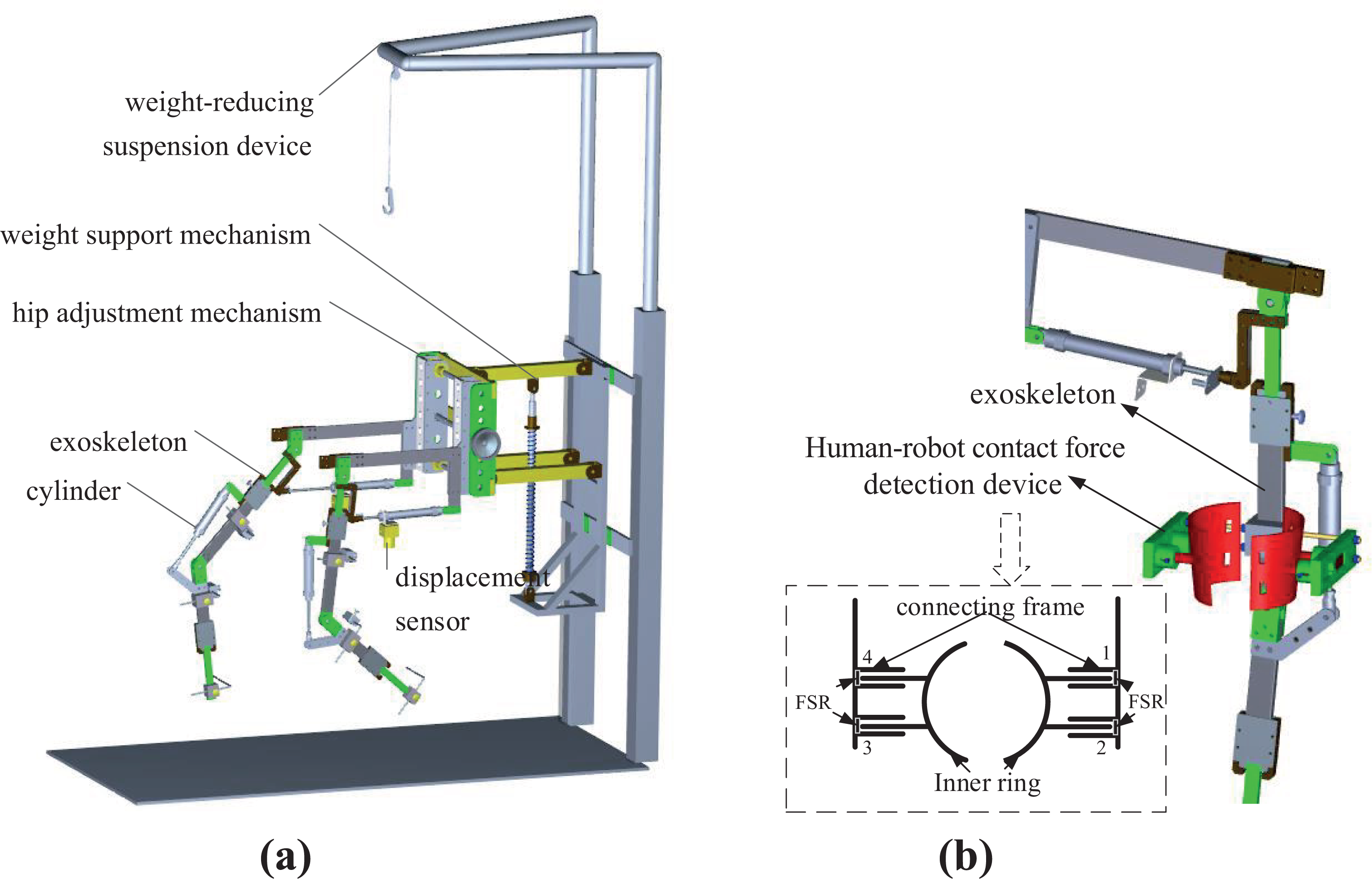
Structure scheme of gait rehabilitation robot: (a) mechanism layout and (b) human–robot contact force detection device installation in robot.
Exoskeleton assists patients and coordinates with the treadmill speed to complete repetitive gait rehabilitation training. The two actuated leg exoskeletons are attached to the patients’ legs. Based on the bionic idea, the unilateral lower extremity exoskeleton is a two-degree-of-freedom (2-DOF) linkage mechanism with a hip joint and knee joint rotating in sagittal plane considering that human walking motion is mainly in the sagittal plane. The linkage mechanism is actuated by pneumatic cylinders to rotate around the axis of each joint to induce flexion and extension movements to realize the organic combination of rigid support and pneumatic flexible drive. In addition, the weight-reducing suspension mechanism partially reduces the load of patient’s lower limbs and balances the height change of the center of gravity during walking.
The linear potentiometer is installed on each cylinder and the joint angle is calculated by the geometric relationship of the mechanism. A human–robot contact force detection device is installed on the thigh linkage of the robot, as shown in Figure 1(b), which consists of inner ring, outer connecting block, and symmetrically arranged film pressure sensors (FSRs). The inner ring which is tied to the lower limb of the patient moves with the affected limb, while the outer connecting frame is fixed on the robot’s thigh. The inner ring convex mechanism is matched with the groove on the outer connecting block, and the FSR sensors are installed inside. There are two FSR sensors installed in the front and back sides, respectively. When the gait rehabilitation training robot is not synchronized with the human lower limb movement, the human–robot contact force in the sagittal plane is measured by the FSRs in real time.
Interactive active compliance control strategy based on admittance model
Determination of human–robot interactive model—Admittance model
Seen from the instantaneous power flow between two or more physical systems, physical systems come in only two types: admittances, which accept effort (e.g. force) inputs and yield flow (e.g. motion) outputs; and impedances, which accept flow (e.g. motion) inputs and yield effort (e.g. force) outputs. 26 For two physical systems in contact with each other, the emphasis of their fusion characteristics is mutual compensation: if the environment is impedance, the robot should show admittance characteristics and vice versa. The patient is regarded as the environment to robot in the rehabilitation task. When the patient has active walking consciousness, the affected lower limb has certain movement ability. The uncoordinated movements between the robot and the patient exert the contact force, so the environment has impedance characteristics. Further, the design of the robot controller should eliminate the contact force, takes the contact force as input and reacts as the motion adjustment. Therefore, the interactive model between the two physical systems (e.g. the patient and the robot) is of admittance characteristics, as shown in Figure 2. It can be seen that there is no force closed-loop in interactive control. The compliance in interaction is embodied in the dynamic relationship of the force and the position, that is, the characteristics of the admittance model.
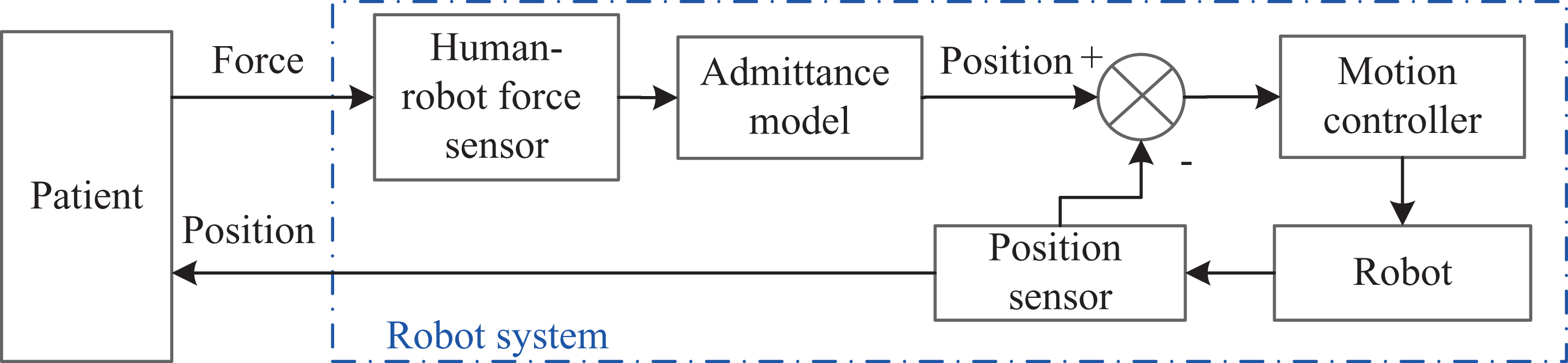
Human–robot interaction in gait rehabilitation training.
The output of admittance model is the adjustment of position denoted as △θ(t), and the desired joint trajectory θ d(t) for the robot is calculated in equation (1), where θ r(t) represents the reference trajectory

The admittance model is the dynamic relationship between the human–robot interaction force F int and the adjustment of position △θ(t). It is given as follows

where M, B, and K are mass, damping, and stiffness coefficient, respectively.
The admittance model transfer function (3) is obtained through the Laplace transformation from equation (2)
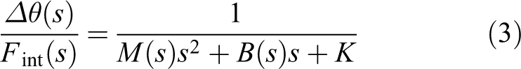
It can be seen from formula (3) that M, K, and B in the admittance model can be used as adjustable parameters. To determine the appropriate adjustable admittance parameters, the influence of each admittance parameter on the control characteristics is studied by simulation, as shown in Figure 3.

Effects of admittance parameters. (a) Effect of stiffness coefficient K, (b) effect of damping coefficient B, and (c) effect of inertia coefficient M.
From the simulation results, we can see that stiffness coefficient K reflects the adaptability of the adjustment of position. The greater the stiffness, the smaller the adjustment of position is. Damping coefficient B reflects the adaptive speed of the adjustment of position. The greater the damping, the longer the rising time is. And with high B value, the same amount of position adjustment needs more energy. The adjustable range of mass coefficient M is limited, because it causes the rapid change of the damping ratio and natural frequency of the system at the same time, which influences the stability of the system. It has little influence on the changeable amount of the position in the limited adjustable range. Therefore, it is not selected as an adjustable parameter of the admittance model. Stiffness coefficient K and damping coefficient B are the adjustable parameters of the admittance model to meet the requirement of the patients during different rehabilitation period.
Admittance parameter adjustment algorithm based on reinforcement learning
In active rehabilitation training, the adaptive parameters (K and B) algorithm is adopted according to the degree of participation of patients. It allows the robot to adapt itself to the patient in the range of stiffness (K up, K dn) and the range of damping (B up, B dn) that are set to ensure the stability of the system. In addition, human walking is a coordinated high-level planning process, and patients have individual walking habits before the impairment of lower limb function. Therefore, reinforcement learning algorithm is applied to the personalized learning of admittance parameters. The purpose of learning algorithm is to find optimal strategies for parameter adjustment suitable for different patients using the collected interactive data of themselves. Using this method, the adjusting process is according to the human control performance and walking habits and adapts to the different disability levels of patients.
Sigmoid function is used in the design of adaptive law. It is continuous, mono-incremental, and bounded in the definition domain (−∞, +∞), and the range is from 0 to 1, as shown in Figure 4(a). It is defined as
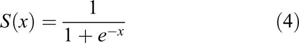
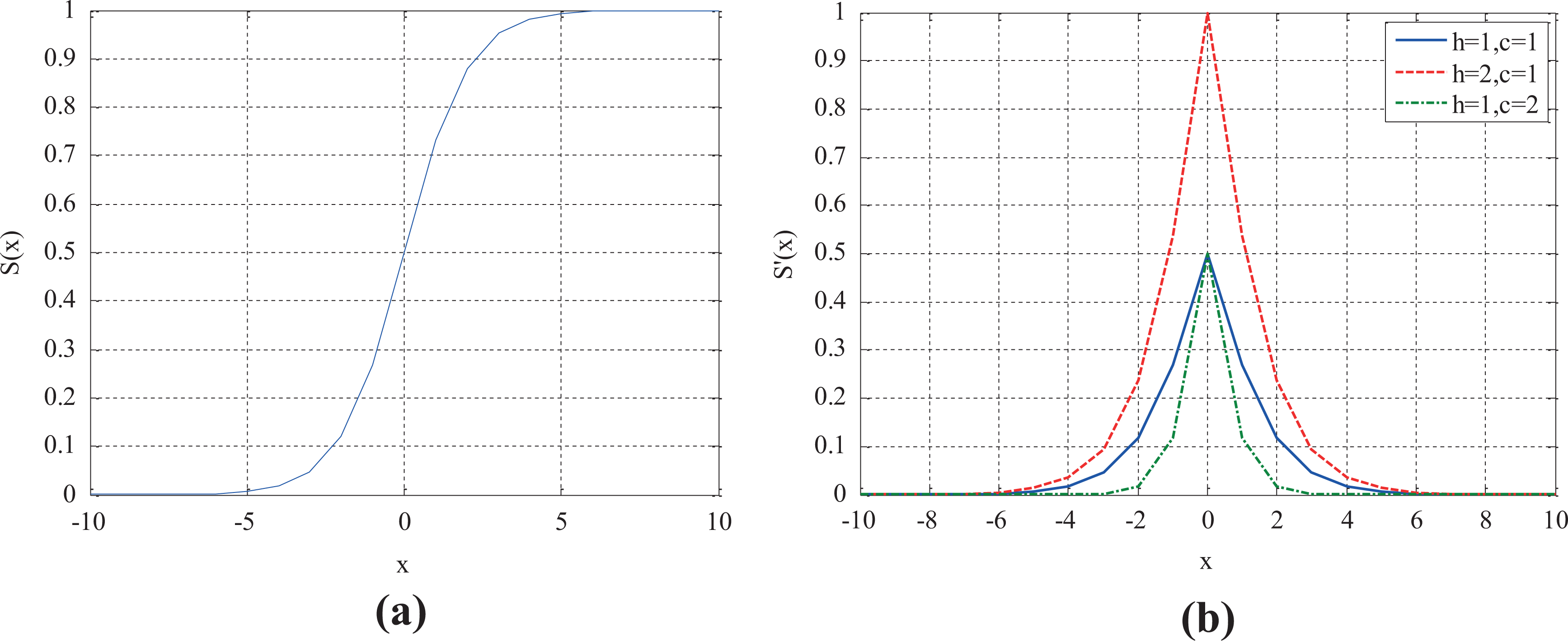
Functions’ graphic representation: (a) sigmoid function S(x) and (b) S′(x).
Based on Sigmoid function, the used function is

where the parameter h is used to adjust the peak value, and the parameter c is used to adjust the concentration of the function, as presented in Figure 4(b).
An adaptive law is proposed to tune the admittance parameters based on equation (5), and the adjusting values of ΔB and ΔK are defined in equation (6), where B up and B dn are the upper and lower limits of damping, respectively; K lup and K ldn are the upper and lower limits of stiffness, respectively; F d is the desired force set according to the evaluation on patient’s condition; h 1, c 1, h 2, and c 2 are the parameters of Sigmoid deformation function defined in equation (5).

In equation (6), h 1, c 1, h 2, and c 2 are the key parameters for the adaptive law. Four adjustment parameters are determined by the designed reinforcement learning algorithm in our study, and the block diagram is shown in Figure 5.

Adaptive admittance parameters adjustment method based on reinforcement learning.
Because the admittance model describes the dynamic relationship between position and force, the choice of learning parameters is related to them. Joint angle error θ
err and human–robot contact force F
int are discretized to form a state set. However, target state is set according to the rehabilitation needs of patients. Comparing the current state with the target state, discrete action is selected by Sarsa(0) algorithm according to the reward and the policy, and finally, the incremental parameters are calculated by the selected actions. Sarsa(0) is an on-policy one-step temporal-difference (TD) reinforcement learning method. Reinforcement learning tasks are described by Markov decision process (MDP). MDP is a mathematically idealized form of the reinforcement learning problem for which precise theoretical statements can be made.
27
This form is characterized by a four-tuple <X, A, P, R>, where X is state, A is action, P is the probability of state transition, and R is reward. For rehabilitation training task, their definitions and the algorithm are designed as follows: (1) State space X and discretization:
Joint angle error θ err and human–robot contact force F int are selected as the system states to form a state space X = {Δθ, F}. These state-values are continuous in actual rehabilitation training, and the continuous states will lead to “dimension disaster,” which may cause the problems of calculation and storage in learning process. At present, to solve these problems, fuzzy logic and neural network methods are often used to discretize or generalize the state; however, these method will lead to the complexity of the algorithm. In our study, an empirical segmentation method is used to divide the continuous values of the angle error and the human–robot contact force into M and N intervals, respectively, to form a 2-D mesh, that is, it is used to represent the whole state space and a 2-D array is used to numbering the grids. There are M × N grids in the state space. Each grid is defined as {s 1, s 2}, where s 1 is indicated angle error interval number in the range of [0, M] and s 2 is indicated human–robot contact force interval number in the range of [0, N].
(2) Action set A:
Action set A is defined as four groups of actions which are expressed as [1, 0], [−1, 0], [0, 1], [0, −1] according to the corresponding up, down, left, and right movements. The selection of the action becomes the search for the optimal route along with the state transition when the target state is given according to the patient’s need. The shortest route is chosen as the optimal policy.
(3) Policy π and probability of state transition P:
Sarsa(0) is an on-policy control method that attempts to evaluate or improve the same policy that is used to make decisions. The ε-greedy policies are applied to the on-policy method, meaning that with probability 1 − ε they choose an action that has maximal estimated action value, but with probability ε, they instead select an action at random, described in equation (7)

where Q(x, a) is the state action-value function, A(x) is the total number of actions contained in a discrete action set, therefore, 1/A(x) is the average probability.
(4) State action-value function Q(x, a) and reward R:
It is easy to devise incremental formula for updating state action-value function as follows
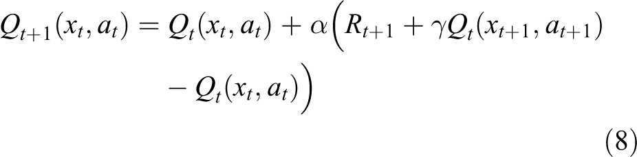
where t is the discrete time step, α is the step-size parameter, γ is the discount-rate parameter, R t+1 is the reward of time t + 1 with transition from state xt to state xt + 1 after taking action a t, represented as follows

where rt + 1 is the immediate reward which is the evaluation of the state-action pair (xt , at ). Its definition directly affects the effect of task execution. The immediate reward rt + 1 is set to constant −1, because we choose the shortest route from the initial grid to the target grid as the optimal policy as mentioned above and it is a failed exploration before the target grid is reached. The immediate reward value set to a constant also simplifies the solving process of the algorithm. However, due to the existence of discount-rate parameter γ, the value of state action-value function increases gradually as the state gets closer to the target.
(5) Adjustment of the parameters:
An incremental formula of the adjustment coefficients h, c is derived from the actions as follows

where M and N are the total number of rows and columns in the state space, respectively; al and ar are the actions times moving along grid columns and rows, respectively.
Interactive control strategy of independent joint
In the early stage of rehabilitation, the psychological bottleneck of patients that they dare not walk should be overcome by passive rehabilitation training. After this stage, patients enter the recovery stage. Then, they will be intended to participate actively. During this period, the patient’s participation movement generates the contact force as an input for the robot from the external environment. The robot with the varying-parameter admittance controller can adjust its behavior by the interactive force feedback and move near the reference gait trajectory to achieve active compliance rehabilitation training. In addition, the admittance parameters are appropriate to the patient based on the reinforcement learning adjustment algorithm. The interactive control strategy of independent joint based on an adaptive admittance model is shown in Figure 6.
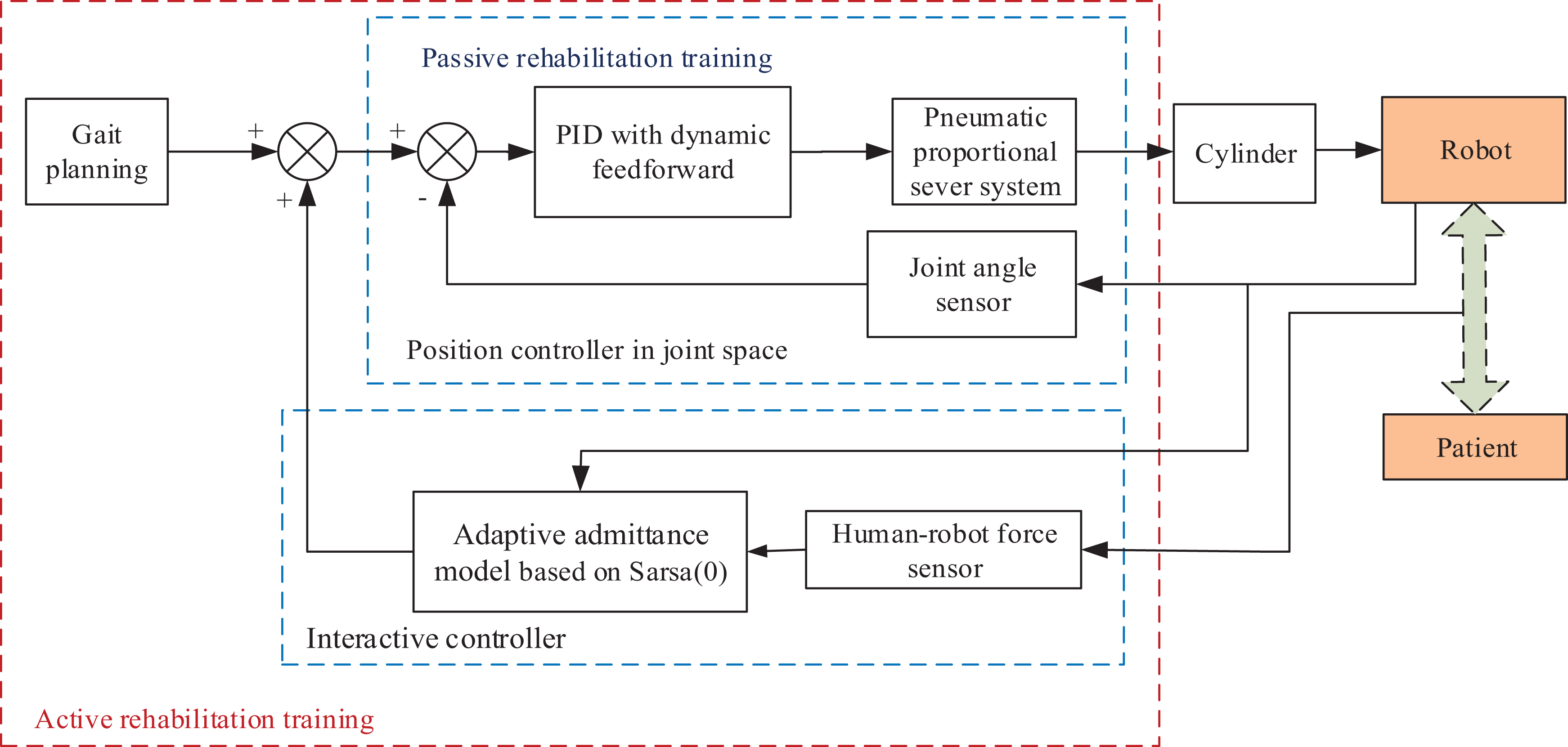
Interactive control strategy of independent joint based on an adaptive admittance model.
The control scheme consists of a position controller implemented in joint space and an admittance controller in interaction space. Trajectory tracking of the robot could be achieved by controlling individual cylinder displacement in joint space. The cylinder is controlled by a pneumatic proportional valve. In consideration of the time delay and nonlinear characteristics of the pneumatic system, an improved Proportion-Integral-Derivative (PID) controller with the dynamic feedforward algorithm is designed. The dynamic feedforward algorithm consists of a velocity feedforward (VFF) algorithm and a gravity compensator (GC), as shown in the following formula (11)
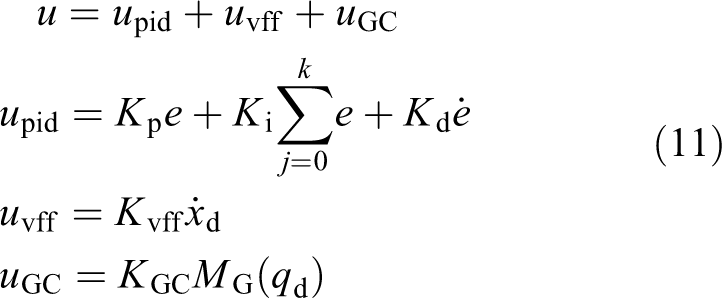
where u is the output of controller; e is the position error; K p, K i, and K d are the proportion, integral, and differential coefficients in PID controller, respectively; K vff is the coefficient of VFF; and K GC is the coefficient of GC, and M G(q d) is the time-varying gravitational moment calculated from desired trajectories.
Simulation and analysis
Simulations are conducted to verify the feasibility of the interactive control system with the hip and knee joint angle data in Clinical Gait Analysis (CGA) 28 database as the reference trajectories. The database is established by capturing a large number of motion information of normal people during walking by 3-D Motion Capture System of Northern Digital Technologies Inc (Ontario, Canada). (NDI). Each group of motion information includes 50 equal interval joint angle sampling points in a complete gait cycle of hip, knee, and ankle joints. The interactive control system is presented in Figure 7.
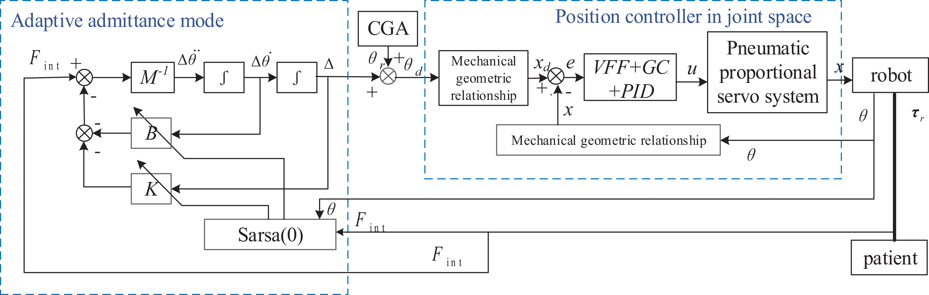
Interactive control system for pneumatic-driven gait rehabilitation training robot. GC: gravity compensator; VFF: velocity feedforward.
Simulation models and parameters
Each leg of the exoskeleton robot is a two-link serial manipulator, which consists of two independent rotating joints, hip and knee, actuated by a pneumatic proportional valve-controlled cylinder system separately. Two pneumatic proportional valves (Festo (Germany), MPYE-5-M5-010-B) are utilized to control the hip cylinder (SMC, CM2C32-125Z) and knee cylinder (SMC, CM2B32-80) with the pressure of 0.4 MPa. Based on the mathematical model of valve-controlled cylinder system, 29 the transfer function between the control voltage u for the proportional valve and the output displacement x of hip cylinder can be obtained with the above pneumatic components parameters, calculated as follows

Also the mathematical model of knee valve-controlled cylinder system is calculated as follows

The geometric relations between joint angle θ and cylinder displacement x are as follows

Each leg of the gait rehabilitation training robot is a 2-DOF mechanism. Its dynamic model is as follows

where subscript “1” represents hip joint parameters while subscript “2” represents knee joint parameters, τ is the joint torque, I is the moment of inertia, m is the linkage mass, rc is the centroid distance, l is the linkage length, θ,
The parameters of the robot in equation (16) are obtained by ProE software (Pro/Engineer WildFire5.0), and the parameters of the lower limbs of the human body are gotten from the national standards of the People’s Republic of China: Inertial parameters of adult human body (GB/T 17245-2004) and Human dimensions of China Adults (GB 10000-88). Taking the exoskeleton robot worn by patients with 1.75 m height and 70 kg weight as an example, the dynamic model parameters are listed in Table 1.
Human–robot system dynamic parameters.

Simulation and analysis
(1) Validity of admittance parameters learning algorithm based on Sarsa(0)
The parameters of the reinforcement learning algorithm are set by trial and error, where α = 0.15, γ = 1, ε = 0.1. Taking CGA standard gait data as input, the learning process of admittance parameters based on Sarsa(0) under time-varying human–robot contact force in a gait cycle is shown in Figure 8. Taking the hip joint as an example, the error of hip joint angle takes 0.2 rad as an interval, and the human–robot contact force takes 2 N as an interval. The angle error and the human–robot contact force are divided into five and nine intervals, respectively, to form a 5 × 9 2-D mesh for the state space.
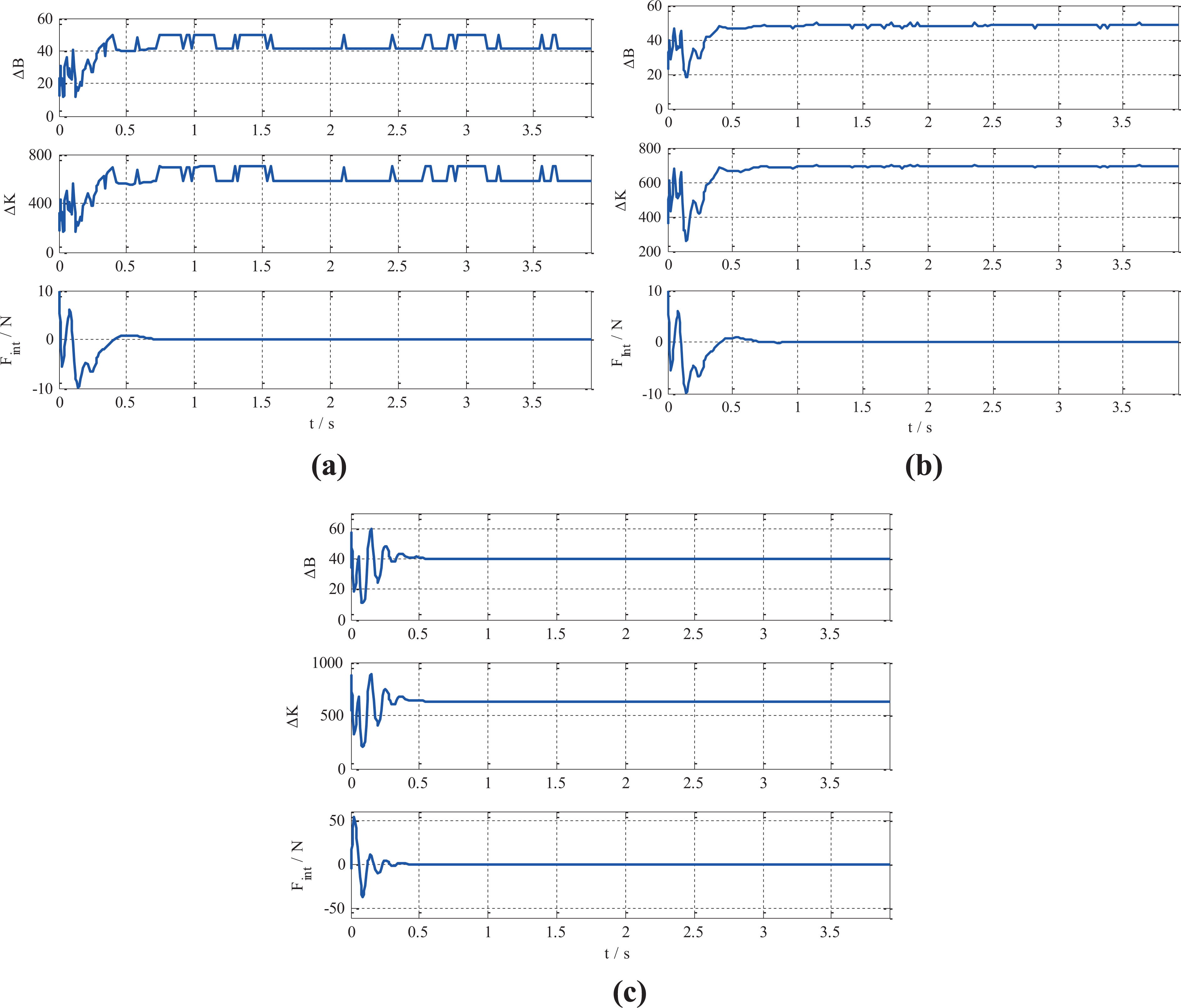
Learning processes of admittance parameters based on Sarsa(0). (a) 10 times learning of hip joint, (b) 50 times learning of hip joint, and (c) 50 times learning of knee joint.
Comparing the results of 10-time (Figure 8(a)) and 50-time parameters learning (Figure 8(b)), we can see that with the increase times of learning, the damping parameters and stiffness parameters gradually tend to be stable. It takes about 0.032 s to complete 50-time learning sessions. Figure 8(b) and (c) indicates that the admittance parameters are smaller when the human–robot contact force is large. The value of B decreases to speed up the angle adjustment, and the value of K decreases to enlarge the angle adjustment range, so that the robot has greater flexibility and faster tracking with the movement of patients. When the human–robot contact force is lowered to zero, the admittance parameters tend to a larger value. Higher stiffness can ensure the tracking accuracy of trajectory, and larger damping can reduce overshoot and enhance the safety of rehabilitation training. Therefore, the learning processes of admittance parameters meet the requirements of both flexibility and safety in active rehabilitation training.
(2) Comparison of Sarsa(0) learning algorithm and non-learning admittance control algorithm
Under the same conditions of the time-varying human–robot contact force, the effects of learning and non-learning control algorithms on system performance are compared, as shown in Figure 9.

Comparison of Sarsa(0) learning algorithm and non-learning algorithm.
With fixed settings of h 1 = 100, c 1 = 0.1, h 2 = 1400, and c 2 = 0.1, the angle adjustment process of the non-learning admittance model is long, multiple fluctuations occur, and the angle adjustment range is large, plot in blue in Figure 8. However, after the learning process comes to the stable with the Sarsa(0) algorithm, along with the change of human–robot contact force, the angle adjustment changes relatively gently, without many oscillations, plot in red. The hip joint angle tends to be stable at 0.5 s and the knee joint angle reaches to be stable at about 0.2 s, which is consistent with the change of human–robot contact force, and the overshoot is small. Because the time-optimal evaluation index is used in the designed algorithm, it can be observed in the simulation that the adjustment time of learning strategy is shorter than that of no-learning strategy. The adjustment values of admittance parameters are compared, as listed in Table 2.
Comparison of two algorithm in admittance parameters adjustment.

K: stiffness coefficient; B: damping coefficient; B pp: peak-to-peak B value; K pp: peak-to-peak K value.
It can be seen that the adjustment range of B of Sarsa(0) learning algorithm is larger than that of Sigmoid algorithm without learning, and the peak-to-peak value (B pp) is larger, while the adjustment range of K value is smaller than that of Sigmoid algorithm, and the peak-to-peak value (K pp) is slightly smaller, listed in Table 2. In brief, the admittance model with Sarsa(0) learning algorithm has larger damping adjustment range and smaller stiffness adjustment range, so the angle adjustment speed is slower and the system is relatively stable. If the spring–damp–mass system is used as an analogy, the model is equivalent to a soft spring. In terms of system dynamic characteristic parameters, the K value affects the natural frequency ω n of the model. If the K value is small, the natural frequency is low, so the rising time is long. The B and K values affect the damping ratio ξ of the model together. Because B is on the molecule and K is on the denominator of the damping ratio ξ, the Sarsa(0) algorithm leads to the increase of the model damping ratio, that is, the reduction of overshoot. Thus, the adjustment of admittance parameters of Sarsa(0) makes the patient feel more comfortable.
(3) Personalized features in reinforcement learning algorithm
Another contribution of reinforcement learning is that the model reflects the patient’s own personalized characteristics by learning with the patient’s sample data. Each patient needs different treatment schemes because of their altered condition. The joint angle and human–robot contact force are selected as two state variables of this algorithm, both of which have personalized characteristics of patients who are training.
As shown in Figure 10, under the same time-varying human–machine contact force (curve in lower left corner), different admittance parameters are obtained by Sarsa(0) algorithm learning with two groups of different CGA data (curves in lower right corner). The admittance parameters obtained by CGA2 group with large joint angle are relatively smaller. From the aforementioned analysis, these lead to the larger value of angle adjustment and the faster adjustment speed. Therefore, for different patients, the influence of joint angle during walking can be reflected in learning algorithm for the parameters of the controller, which has personalized characteristics of themselves.

Admittance parameters learning curves with different CGA data. CGA: clinical gait analysis.
Experimental results
The interactive control experiments are conducted on the prototype of gait rehabilitation training robot (Figure 11) under two modes of passive rehabilitation training and active rehabilitation training.

Experimental system of the rehabilitation training: (a) human–robot contact force detection device and (b) gait rehabilitation training robot prototype and tester.
Experimental system and protocol
At present, it is in the prototype stage. A healthy person (male, 26 years, 1.75 m height) participated in this study. Before the training, he wore the exoskeleton robot prototype, which was adjusted in accordance with the length of his lower limbs and tied the hip and knee joints together with a strap. The inner ring of the human–robot contact force detection device we developed closely surrounded the tester’s thigh. Along with the walking, the human–robot contact force was measured in real time. And two linear potentiometers (KTM-125 L (Taizhou Jiaojiang Xiyu Electronics Factory, Taizhou, China), KS15-150-05 (Jinan Kaisi Technology Co., Ltd., Jinan, China)) installed on the hip cylinder (SMC (Japan), CM2C32-125Z) and the knee cylinder (SMC, CM2B32-80) measured the displacements to calculate the corresponding joint angles of the robot. The measurement and control system was constructed by the semi-physical real-time system provided by the LinksRT company (Beijing LINKS Technology Co., Ltd., Beijing, China), including an A/D board (Ni6259) for analog input and a D/A board (Ni6216) for digital output for the pneumatic proportional valves (Festo, MPYE-5-M5-010-B). The pneumatic system was supplied with the pressure of 0.4 MPa.
The treadmill speed was set to 0.8 km/h in active rehabilitation training experiment. Sensors data for all experiments were collected at 100 Hz. The hip and knee sagittal plane physiological gait data in CGA database were used to define the reference joint angle trajectories.
Passive rehabilitation training experiment
The treadmill was stationary in passive rehabilitation training experiment. The right leg of the tester stood on the treadmill as a support. The left leg is worn in the exoskeleton, and it is lifted up, driven entirely by the robot, which simulated the patient’s passive rehabilitation training, that is, the left lower limb of the human body had no initiative. The gait cycle is 5.6 s. This experiment completed 10 gait cycles of passive training. The parameters for position controller (formulas (11)) in the experiment are given in Table 3.
Position controller parameters.

K p: proportion coefficient; K i: integral coefficient; K d: differential coefficient; K vff: coefficient of VFF; VFF: velocity feedforward; K GC: coefficient of gravity compensator.
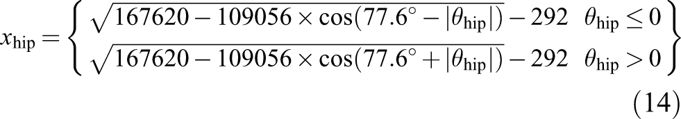
The synchronous detection of the cylinder displacements x and the human–robot contact force from the beginning to three gait cycles are selected for analysis purpose, presented in Figure 12. The desired trajectories x d of the hip and knee cylinders are calculated from the CGA data by equations (14) and (15), plot in blue and cyan dotted lines, respectively.

Experimental curves of passive rehabilitation training.
The measured human–robot contact force is very small in passive rehabilitation training. In preparation stage during 0–10 s, the exoskeleton robot drives the lower limbs of the tester from the upright state to the leg-lifting state. The joint motion angle varies slowly and the human–robot contact force is only about 1 N during this period. Then in the normal gait cycle, the human–robot contact force slightly increases due to the large motion range of joint. The range of human–robot contact force in the experiment is (0.81, 2.98) N. Because the purpose of passive rehabilitation training is to let the affected limb walk in accordance with the predetermined trajectory without active consciousness, there is no force outer-loop in the control strategy and only the inner-loop position controller acts. From the measured curves of displacement, it can be seen that the time lag characteristics of the pneumatic system are suppressed by velocity feedforward of the position controller. Thus, the cylinders’ displacements are synchronized with the desired trajectories in each gait cycle. However, there are always some errors and oscillations in the peak value of the hip joint. The time for arrival of the peak value is just the transition stage from the joint extension to flexion, and the cylinder is required to change direction. Therefore, there are a lot of uncertain factors such as friction and impact when cylinder is reversing. The friction moment is not compensated in the control strategy. Another reason is that the robot hip joint bears the weight of the human lower limbs and exoskeleton mechanism, while the gravity compensation coefficient is a fixed value. The above factors lead to the errors of the peak value. Although the knee joint has the above problems, the error is less than that of the hip joint because of its smaller load. Therefore, the passive rehabilitation training experiment verifies the effectiveness of the inner-loop position control strategy, which can meet the demands of gait tracking accuracy in rehabilitation training.
Active rehabilitation training experiment
In the active rehabilitation training experiment, the left leg of the patient was no longer suspended, but the lower limbs walked on the treadmill. When the treadmill speed is set to 0.8 km/h, the gait cycle of human walking is 4 s. The reference trajectories of the hip and knee cylinders and the control parameters of the position controller are consistent with those set in the passive rehabilitation training experiment. The measured data from the beginning to the four gait cycles are selected for analysis purpose, presented in Figure 13.
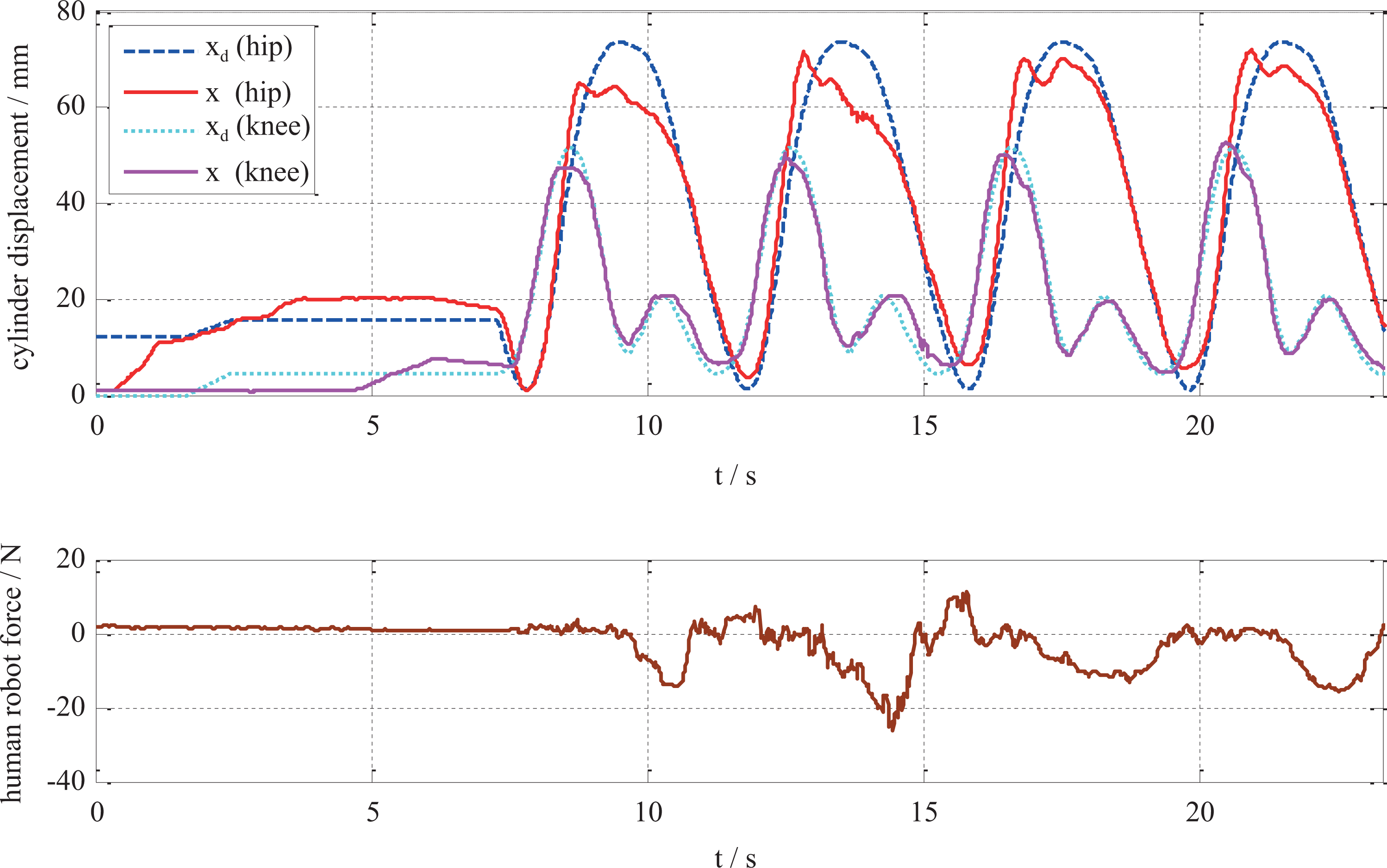
Experimental curves of active rehabilitation training.
The tester’s initiative leads to the increase of human–robot contact force in active gait rehabilitation training. In the preparation stage when the exoskeleton robot drives the lower limbs from the upright state to the leg-lifting state, the human–robot contact force is only (0.61, 2.15) N, because the joint motion angle varies slowly as the passive training. With the beginning of the normal gait training, the human–robot contact force increases, and the range of human–machine contact force is (−26.21, 11.06) N. The human–robot contact force increases significantly compared with the passive rehabilitation training process because of the active participation of the tester. The purpose of active rehabilitation training is to encourage patients to participate actively with the robot providing part of the help and adapting to human movements to make the human body feel comfortable. Next, the compliance of the robot is verified with the interactive control strategy, with B and K being adjusted based on equations (6) and (10). At present, the human–robot contact force detection device is only installed on the left thigh; so, just the hip motion control is verified.
Dynamic admittance parameters are the key factors for trajectory adjustment to realize the compliance of the robot. From the recorded experimental curves of active rehabilitation training (Figure 12), it can be seen that the human–robot contact force in the initial stage (0–7.3) s is small, so the adjustment parameters are no longer presented. In the normal four gait cycles from 7.3 to 23.3 s, the admittance parameters changing processes based on reinforcement learning algorithm and the hip joint angle adjustment are recorded as well as the measured interaction force, as shown in Figure 14.

Adjustment curves of admittance parameters and the hip joint angle trajectory.
Seen from the angle curve of hip joint, the desired angle θ
d for the robot deviated from the reference angle θ
r. It is caused by the force feedback to the controller. Detailed analysis and discussion are as follows: Parameters B and K decrease as the contact force increases while increase as the contact force decreases. The adjustment range of parameter B is (15.63, 58.8) and that of parameter K is (206.04, 886.17) based on the Sarsa(0) algorithm. The adjustment of parameters is synchronized with the change of human–robot contact force. When there exists a large contact force between the robot and the patient, the angle adjustment value Δθ is also large, which is the output of the admittance model. It leads to the desired angle θ
d for the robot being deviated from the reference angle θ
r to make the robot following patients. In the second gait cycle, the contact force is the largest and the adjustment of the angle is also the largest. With the better cooperation of the human and the robot in the third gait cycle, the adjustment of the angle is also reduced, which shows that the robot dynamically adapts to the lower limbs of the tester who has the active participation. There are two peaks of contact force in each gait cycle. When the contact force is negative, it indicates that the lower limbs of the tester lag behind the robot, then the angle adjustment curve θ
d is slightly ahead of the reference curve θ
r and vice versa. Comparing the measured displacement x curve of the hip joint cylinder in Figure 13 with the angle trajectory θ
d of the robot adjusted by the human–robot contact force in Figure 14, the trends of them are in line. The robot legs walk according to the adjusted θ
d actuated by the cylinder, instead of the initial reference joint trajectory θ
r. It shows that the gait accuracy is sacrificed in active rehabilitation training, but it provides flexibility for patients to participate actively. Nevertheless, there are upper and lower limits in the adjusting range of parameters B and K. In this experiment, the adjusting range of B is (20, 60) and that of K is (200, 900). Both are determined through trial and error, thus it ensures that the adjusted angles do not exceed the range of joint motion of human physiological characteristics.
Discussion and conclusion
Whether impedance control or admittance control is employed in the process of human–robot interaction, the self-adaptation of model parameters is the focus of current research. The self-adaptation is mainly realized by discrete selection and continuous adjustment. For example, a velocity-based impedance parameter selection method was proposed by Erden and Mari. 30 The velocity threshold and the corresponding damping parameter empirical values were chosen according to the experience. The principle of the variable impedance control strategy was simple, which reflected the adaptability adjustment of the model parameters to a certain extent. However, the discrete impedance parameter reduced the controllability and fluency of operation. To achieve continuous model parameter adjustment, researchers began to infer human operation intention by monitoring the motion of the manipulator in the process of human–machine interaction. For example, in the control of Lokomat, 20,21 real-time monitoring of joint angles was adopted, and the stiffness and damping values of the impedance controller were continuously adjusted using the function between the joint angle and the stiffness parameter, as well as the relationship between stiffness and damping. In control of CARR robot, 23 the K and B values of the admittance controller were adjusted online using the designed adaptive law among the measured joint angle, the joint moment, and the computational moment.
Most of the adaptive impedance or admittance interactive control strategies mentioned above adopt the method of constructing functions to adjust the parameters without considering the individualized characteristics of patients or manipulators in the interactive process. The parameters in the function depend largely on the designer’s subjective intention or the practical experience of a specific task. Although the robot can dynamically adjust with the interaction information, it is more flexible than the interactive control under fixed parameters; it needs to reset the parameters to the function when facing different patients to provide more natural rehabilitation training experience for them. Manual modification of parameters in functions requires experience and a certain amount of time to explore. It is also inconvenient for computer control.
To overcome the abovementioned limitations, the interactive control based on reinforcement learning is proposed in this study. The interactive control strategy of rehabilitation training robot is conducted by the two-loop nested control structure of interaction space and joint space to realize two training modes: passive rehabilitation training and active rehabilitation training. The joint space control strategy adopts the independent joint decentralized control algorithm. The feedforward compensation of dynamic characteristics is added, which improves the performance of the PID controller in consideration of the nonlinearity and modeling error of the pneumatic system. An adaptive admittance model is used in the interactive control strategy to stimulate the training initiative of patients. The parameter adaptive law is designed using the deformation formula of sigmoid function to meet the needs of a dynamic and time-varying interaction process. In addition, a personalized parameter learning method based on reinforcement learning is proposed. A 2-D mesh of state variables is constructed by discretizing human–robot contact force and joint angle errors, so the personalized characteristics of patients are quantified in the learning algorithm. Individualized admittance parameters suitable for the patient are obtained by reinforcement learning. The proposed techniques in this study contribute to personal adaption and active compliance in robot-assist rehabilitation training. To the best of the authors’ knowledge, the interactive control based on reinforcement learning with the pneumatic driven lower limb rehabilitation training robot has not been reported in literature.
The next step is to realize the active resistance rehabilitation training. Instead of setting the expected human–robot contact force to be zero, the desired force is given according to the patient’s need. Through the admittance model, the stable contact force is always needed to be overcome to provide resistance for the patient’s rehabilitation training. At the same time, clinical experiments will be carried out as soon as possible to further optimize the design of the system.
Footnotes
Declaration of conflicting interests
The author(s) declared no potential conflicts of interest with respect to the research, authorship, and/or publication of this article.
Funding
The author(s) disclosed receipt of following financial support for the research, authorship, and/or publication of this article: This study was supported by the “Research on key generic technologies of pneumatic gait rehabilitation training robot” project (Grant No. 172102210036) and “Research on key technologies of human–robot harmony for gait rehabilitation training robot” project (Grant No. 192102210065) granted from “Project of science and technology of the Henan Province.”.