
Abstract
A Strapdown Inertial Navigation Unit (SINU) is a low cost motion measurement device commonly used for navigation solutions. Global Positioning System (GPS) is usually adopted as an external reference source to minimize the SINU's accumulation errors by applying a Kalman filter to obtain best estimations in positions, velocities and orientations. However, due to the low sampling rate of GPS, such a configuration does not provide intensive orientation estimation. In this paper, a new and efficient real-time GPS-aided SINU system with incorporated magnetometers is developed to enhance the orientation estimation. An intensive orientation estimation algorithm is developed by combining the extra sensory inputs from magnetometers with the inputs from accelerometers. The estimated orientation was applied in the Kalman filtering, replacing the GPS-aided orientation estimation. The offline implementation shows promising results in reducing both the accelerometers' and gyroscopes' errors. Finally, the design is successfully implemented in real-time.
1. Introduction
An inertial navigation system, which relies on inertial sensors [1] to navigate, has been an important tool in position, velocity and orientation measurements for the past few decades. A high performance inertial navigation system which uses accurate inertial sensors is generally very expensive and is controlled by government regulations [2], resulting in such a system being unusable for civilian applications. These constraints have led to the development of a low cost Strapdown Inertial Navigation Unit (SINU) [3]. A typical SINU consists of three orthogonally aligned accelerometers and three orthogonally aligned gyroscopes fixed in a prescribed position. However, its measurements are highly inaccurate and are jeopardized by various noises [4,5], which include both deterministic and random noises. The effect of these noises that cause the inaccuracy can be reduced, but not eliminated, through proper calibration [3,4]. To increase the SINU's accuracy, the dead reckoning technique through the use of Global Positioning System (GPS) and the implementation of a Kalman filtering algorithm has been proposed [6]. Such a technique is known as a GPS-aided SINU system with Kalman filtering, and it had been successfully applied in various applications such as unmanned aerial vehicle (UAV) navigation [7], land vehicle navigation [8,9] and autonomous underwater vehicle (AUV) navigation [10].
A fully calibrated SINU can achieve short-term accuracy with a relatively fast sampling rate (40∼200Hz), but it always suffers from long-term measurement inaccuracy. On the other hand, a GPS possesses the characteristic of long-term accuracy, but it has a relatively slow sampling rate (<5Hz) as compared to SINU. The conventional GPS-aided SINU system combines the merits of both systems to achieve position, velocity and orientation measurements [6–11]. However, due to GPS's inability to provide reliable orientation measurements, especially during stationary [2], this conventional system cannot achieve efficient orientation measurements.
In this paper, an improved navigation system is proposed by adding-in additional sensory inputs from three orthogonally aligned magnetometers. The magnetometers measure the magnetic field from the South Pole to the North Pole, which can be processed to provide an angular measurement. Such a configuration improves the orientation measurement, which in turn improves the overall performance of the navigation system. Both the proposed system and the conventional system have been developed. Navigation experiments were conducted to compare and analyse the performance of both systems offline. The developed navigation system will eventually be incorporated into an Unmanned Aerial Vehicle Synthetic Aperture Radar (UAVSAR) [12] system to measure the UAV's motion in order to achieve motion compensation in SAR signal processing [13].
The remainder of this paper is organized as follows. Section 2 describes the fundamental principles of inertial sensing and motion equations. Section 3 outlines the modelling of both conventional and improved GPS-aided SINU systems using a Kalman filter. Section 4 presents the offline implementation of both conventional and improved GPS-aided SINU systems. Section 5 introduces the real-time implementation of the improved GPS-aided SINU system using an embedded computer, and lastly,Section 6 concludes the findings.
2. Navigation Equations and Its Dynamic Error Model
2.1 Coordinate Frames
A conventional inertial sensor provides measurements in terms of acceleration and angular velocity. It is customary to represent these measurements in various frame representations [2,3,6,7], which include:
The inertial frame, or i-frame, with its origin positioned at the centre of the Earth and axes which are non-rotating with respect to the fixed stars. The Earth frame, or e-frame, with its origin positioned at the centre of the Earth and rotating axes. The z-axis points toward the North Pole, the x-axis points to the reference meridian and y-axis completes the right-handed orthogonal frame. This frame is also known as an Earth-Centred Earth-Fixed (ECEF) frame. The navigation frame, or n-frame, is a local geographic reference frame with its origin located at the centre of the navigation system, and its axes follow the right-handed orthogonal rule with x-axis pointing toward the North Pole, y-axis pointing toward the East, and z-axis pointing toward the Earth's centre. It is also known as a North-East-Down (NED) frame. The body frame, or b-frame, is a set of axes that follows the right-handed orthogonal rule which is aligned with the yaw, pitch and raw axes of the system.
The inertial sensors provide direct measurements in terms of b-frame. To utilize these measurements for navigation applications, the b-frame measurements must be converted into n-frame. This process is known as plane rotation and it is an essential process for all inertial navigation system.
2.2 Plane Rotations
Plane rotations are commonly applied to mathematically expressthe coordinate transformation from one coordinate frame to another. Coordinate transformation involves a sequence of plane rotations equivalent to multiplying the coordinate frame with the directional cosine matrix (DCM):

where Fa and F
b
representthe coordinate framesa and b, with φ, θ and Ψ representing the roll, pitch and yaw, respectively, and Equation (2) representing the DCM of frame transformation from frame a to frame b:
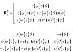
where c(.) and s(.) denote the cosine and sine operators.
2.3 Navigation Equations
The GPS-aided SINU system provides outputs in terms of position, velocity and orientation measurements. The navigation equations describe the relationship between the GPS-aided SINU system's outputs and inputs in terms of accelerations and angular velocities. The navigation equations, in their general form, can thus be derived based on the inertial measurements as follows:


where
The navigation equations can be rewritten in discrete form since the GPS-aided SINU system is usually implemented in discrete time, as follows:

where Δt denotes the discrete sampling time.
2.4 Dynamic Error Model
Perturbation is a process of linearizing the nonlinear differential equations in order to perform error analysis [14]. The derivation of SINU's dynamic error equations can be achieved by performing perturbation analysis on Equation (3), and the perturbed equations are:

where
Equation (6) illustrates the general dynamic error model of navigation equations in n-frame. The position error dynamics δṙn can be expressed as functions of position errors δ
Equation (6) can be rewritten in terms of state space model for error prediction using the Kalman filter [15], as shown below:
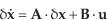
with:


where
It is noted that the error vectors
Equation (7) can be transformed into its discrete form, as shown below:

where Ψk-1 denotes the transition matrix with:

and
where
3. Kalman Filter Modelling
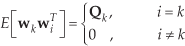
Equation (7) describes the SINU's dynamic error model in the state space model. It is converted into discrete form in Equation (10) for practical implementation using a digital processor. Equation (10) serves as the prediction equations for the Kalman filter. To complete the Kalman filter modelling, the following observation (or measurement) equations are needed:

where

where
Figure 1 shows the operational block diagram of the Kalman filter and the discretized navigation dynamic error equations, with δx̂ k − and δx̂k represent the priori and posteriori estimate respectively, P k − and Pk represent the priori and posteriori estimate error covariance respectively, and Kk is the gain factor.

Operational description of the Kalman filter
As can be seen in Figure 1, the Kalman filtering proceduresare grouped into two processes, known as the Prediction process and the Measurement process, which can be achieved in five steps. In the Prediction process, the priori errors are estimated through Equation (10) and the priori error covariance is predicted. In the Measurement process, the Kalman gain is first calculated and it is used to correct the priori measurement and the priori error covariance. In summary, the Kalman filter acts as a recursive filter to compute the state δ xk based on the prediction and measurement.
In the inertial navigation system, the measurement vector

where the vectors

where Equation (16) represents the orientation measurement of conventional GPS-aided SINU with no magnetometers, and:


where equations (17) and (18) represent the orientation measurement of GPS-aided SINU with magnetometers. Note that sn and mn refer to the 3-dimensional accelerations and magnetic field strength, respectively, in n-frame.
Equation (16), (17) and (18) signify the differences of the conventional GPS-aided SINU system when compared to the enhanced system in identifying the Kalman filter's observation equations. The enhanced system with magnetometers offers a relatively faster orientation measurement as compared to the conventional system which uses GPS for orientation measurement, thus achieving a better performance in orientation estimation.
4. Offline Implementation
Offline field experiments were carried out to verify the performance of the developed GPS-aided SINU system before real-time implementation. The Kalman filter processing is carried out in offline mode to verify the performance of the developed system as compared to the conventional system. The update rates of GPS and SINU were 5Hz and 40Hz, respectively. Calibration [4] was performed on the SINU before carrying out the experiments.
Figure 2 and Figure 3 show the offline comparison of the accelerometers' and gyroscopes' error estimations in one of the field experiments. The straight lines represent the estimated errors through conventional, no magnetometers approach. The dashed lines represent the estimated errors of the enhanced system with additional measurements from magnetometers. Figure 2 and 3 show significant improvements on the estimated errors on both accelerometers and gyroscopes, especially on δ fz and δSwz, by employing the enhanced system. The average estimated errors of the enhanced system are kept to be within ψ2.6×10⁻³ m/s2 for accelerometers and ψ3.2×10⁻⁴ rad/s for gyroscopes. Compared with the conventional system, the average estimated errors are ψ1.26×10⁻² m/s2 for accelerometers and ψ1.7×10⁻³ rad/s for gyroscopes. The results clearly indicate the improvement of the performance of the enhanced GPS-aided SINU system.

Comparison of accelerometers' estimation errors using the GPS-aided SINU system with the Kalman filter – with and without magnetometers

Comparison of gyroscopes' estimation errors using the GPS-aided SINU system with the Kalman filter – with and without magnetometers
Figure 4 shows the field experiment results by comparing the navigation paths under three different scenarios. A zoom-in figure is provided in Figure 4, with average difference computed to be 2.84m between the navigation paths of the GPS-aided SINU system with and without magnetometers. The difference between the navigation paths of GPS measurements and the GPS-aided SINU system with magnetometers is computed to be ψ0.173m. On the other hand, the difference between the navigation paths of GPS measurements and the GPS-aided SINU system without magnetometers is computed to be ψ2.67m. The results clearly indicate the improvement in the navigation path prediction with the implementation of magnetometers in the GPS-aided SINU system.

Comparison of navigation path of the GPS-aided SINU System with the Kalman filter – with and without magnetometers
Figure 5 shows the actual GPS plot using Google Earth.

Actual navigation path of GPS using Google Earth
5. Real-Time Implementation
A Graphical User Interface (GUI) for the real-time GPS-aided SINU system with magnetometers using the Kalman filter is developed using Visual Basic and implemented in a Microsoft Window environment using an embedded computer. Figure 6 shows the simplified operational block diagram of the real-time implementation. The SINU's data rate is 40Hz, which is comparatively faster than the GPS's 5Hz data rate. When GPS data is absent, the system computes the position, velocity and orientation solely from the SINU's data and the previous predicted errors. On the other hand, when GPS data is present, the system computes the position, velocity and orientation by combining both GPS and SINU data.

Block diagram of the real-rime GPS-aided SINU system implementation
Table 1 shows the list of data that the GUI recorded. A total of 31 variables were saved into a solid state hard disk continuously in binary file format. As referred to Table 1, the first nine variables represent the raw data from the SINU, which is commonly known as the inputs of the GPS-aided SINU system. The next 15 variables represent the computed 3-dimensional position, velocity, orientation, acceleration errors and orientation errors, which is also known as the output of the GPS-aided SINU system. The last seven variables indicate the GPS data, which are particularly important in the Kalman filtering of the GPS-aided SINU system.
Data recorded by the GUI

Figure 7 shows the GUI layout of the developed real-time GPS-aided SINU system. The top left corner indicates the serial ports setting for the SINU and the GPS. An “Operation Start” button is located beneath the “CommPort Configuration” frame. An X-Y graph is used to display both the GPS path (the green line)and the SINU's navigation path (the red line). A group of real-time updating parameters, including the real-time updated position, velocity, orientation and GPS information, can be found below the X-Y graph. The raw SINU data is displayed at the bottom of the GUI. Note that the X-Y graph shown in Figure 7 indicates the GPS-aided SINU's real-time implementation result in one of the field experiments.

The real-time GPS-aided SINU system's GUI layout
The results from another field experiment are shown in Figure 8. Its post-processing result is shown in Figure 9. The difference between the navigation paths of GPS measurements and the GPS-aided SINU system for both the real-time processing and the post-processing are computed to be ±0.246m. Finally, Figure 10 shows the actual GPS plot using Google Earth.

Real-time GPS-aided SINU system's experiment result

Offline processing of GPS measurement and GPS-aided SINU measurement

Actual navigation path of the real-time field experiment
6. Conclusion
This paper presents the design and development of a new real-time GPS-aided SINU system using an embedded computer. A conventional GPS-aided SINU system has been developed and the results are compared with the conventional system. Offline implementation was performedon the new system and the conventional system, and the results indicate that the new system has betterperformance and accuracy over the conventional system in terms of position, velocity and orientation measurements. Finally, the proposed new system had been implemented in real-time. The result from the real-time implementation have proved to be identical to the results from the offline implementation, which signifies the success of the implementation of the new real-time GPS-aided SINU system.
Footnotes
7. Acknowledgments
The authors would like to express their appreciation to Tan Wei Qiang, Yee Kuo Shenand Cheaw Wen Guey for their technical support in carrying out the field experiments.