
Abstract
This paper addresses the problem of position control for robot manipulators. A new control structure with compensation for global position is presented. The main contribution of this paper is to prove that the closed loop system of the nonlinear robot dynamics model and the proposed control algorithm is globally, asymptotically stable and in agreement with Lyapunov's direct method and LaSalle's invariance principle. Besides this, the theoretical results in a real-time experimental comparison are also presented to show a comparison of the performance between the square root type controller and simple PD scheme on a three degrees-of-freedom direct-drive robot.
1. Introduction
Industrial robots are basically positioning and handling devices. A useful robot is one that is able to carry outa programmed task. The control of robot manipulators requires knowledge of the dynamics model and its mathematical properties. The problem of position control (also called regulation) is one the most relevant issues in robotics - this is especially so in the case of motion control or trajectory control. The main goal of position control in a joint space is to move the manipulator end-effector to a fixed desired target, which is assumed to be constant regardless of its joint position. In position control, the simple PD scheme was the most widely used algorithm studied in Takegaki and Arimoto [1]; meanwhile, Arimoto and Miyazaki [2] yield a global asymptotically stable closed-loop system for a trivial selection of proportional and derivative gains [2]. By way of contrast, the simple PID control is another popular strategy. However, it lacks a global asymptotic stability proof [3–5].
In recent years, various PD-type control schemes have been developed for the position control of robot manipulators. Among them, the following can be cited: a class of PID and PD controllers for position in [3–5]; a PD controller with proportional and derivative gains as nonlinear functions of the robot's states proposed in [6]; the methodology of energy shaping to propose many global regulation schemes in [7–8]; energy functions based on Lyapunov's stability theory to design control schemes in [9–13]; a sliding PID control for robot manipulators in [14]; a control algorithm with fuzzy logic in [15]; and a methodology on
In view of the simplicity and applicability of the simple PD control in industrial applications, the main motivation of this paper is to propose both theoretical development and practical applications with high performance.
The objective of this work is to present a new control scheme that leads to global asymptotic stability in agreement with Lyapunov's direct method and Lasalle's invariance principle of the closed-loop system as formed by the nonlinear dynamics model of a n degrees-of-freedom robot manipulator and the control structure. The new family has a nonlinear structure, which incorporates square-root type-components to quickly drive the position error to equilibrium point. The proposed control falls into the category of joint-level control and it requires that the set-point or desired position will be given at the joint space.
This paper also presents real-time experiments for position control on a three degrees-of-freedom direct-drive robot manipulator. The experimental results consist of a comparison of the performance between the proposed control and a popular PD scheme using the
This paper is organized as follows. Section 2 recalls the robot dynamics and useful properties for stability analysis. In Section 3, the proposed algorithms for the control and analysis of global asymptotic stability are presented. Section 4 describes the experimental setup based on the three degrees-of-freedom direct-drive robot manipulator and the experimental comparison between the proposed scheme and PD control. Section 5 contains the experimental comparison between PD and square root-type controllers. Finally, some conclusions are offered in Section 6.
2. Robot dynamics
The dynamics of a serial n-link rigid robot manipulator with viscous friction can be written as [17–18]:

where
It is assumed that the robot links are joined together with revolute joints. Although the dynamics model (1) is complex, it has several fundamental properties which can be exploited to facilitate control system design. In particular, the following are useful.
Property 1:the matrixC(qq̇)and the time derivate of the inertia matrixṀ(

This property is called skew symmetry and implies that the robot dynamics define a passive mapping between joint torque and joint velocity.
Property 2: the time derivative of the inertia matrix Ṁ(

Property 3: the matrixC(
3. Square root-type controller
In this section, we present the stability analysis of the equilibrium point for the closed-loop system formed by a nonlinear robot dynamics model and the proposed control scheme. The main feature of this new algorithm is that global asymptotic stability is guaranteed with torques inside the prescribed bounds and the response is smooth without oscillations.
Consider the following control scheme with gravity compensation given by:
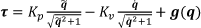
where Kp∈ℝ
n × n
istheproportionalgain, which is adiagonal matrix, Kv∈ℝ
n × n
isa positivedefinite matrix (also calledderivativegain),

Figure 1 shows the profile type for the proposed control structure - it is a continuous function, monotonically increasing and it is also bounded.
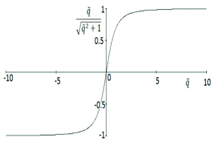
Saturated function for the control structure.
The control problem can be stated as to find a control lawτand select the design matricesKp and Kv, such that the position error q˜(t)and joint velocityq̇(t)vanish asymptotically to zero (the equilibrium point is achieved), i.e.:
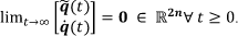

Which is an autonomous differential equation and the origin of this joint state space is its unique equilibrium point.
We propose the following Lyapunov function candidate to carry out the stability analysis of equation (6):

The first term of V(q˜,q̇) is a positive function with respect to the state variable q̇ because M(
Therefore, equation (4) is a globally positive definite and radially unbounded function.
The time derivative of the Lyapunov function candidate (7) along the trajectories of the closed loop equation (6) is given by:

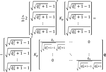
Because Kp is a diagonal matrix, then expression (9) is given as:

After some algebra and using certain useful properties from the dynamics model, equation (8) can be written as:


The equation (13) is a globally negative semi-definite function because Kv,B∈ℝ n × n are positive definite matrixes. Therefore, the stability of the equilibrium point is concluded. In order to prove global asymptotic stability, the autonomous nature of equation (6) is exploited to apply LaSalle's invariance principle, as follows:
Let the region:

Since V̇(q˜,q̇)≤0 ∈ Ω, then V(q˜(t),q(t))is a decreasing function of t and V(q˜,q̇)is continuous on the compactset Ω,which is bounded from below Ω, - for example, it satisfies V(q˜(0),q̇(0))≥V(q˜(t),q̇(t))>0. Therefore, V(q˜(t),q̇(t)) has a limit a ∈ ℝ+ as t→ ∞. Hence, V̇(q˜(t),q̇(t))=0. Since Ω is an invariant set, the unique invariant isq˜ = 0 and q̇ = 0. Since the trivial solution is the unique solution of the closed-loop system (6) restrictedto Ω, then it is concluded that the origin of the state space is globally asymptotically stable.
4. Experimental setup
The experimental setup is a platform based on a three degrees-of-freedom direct-drive robot manipulator for research in robotics. It has been designed and built at the Benemérita Universidad Autónoma de Puebla, México. The robot manipulator moves in three dimensional space, as shown in Figure 2.

Experimental direct-drive robot manipulator
The experimental robot consists of links made of 6061 aluminium actuated by brushless direct-drive servo actuators from Parker Compumotor so as to drive the joints without gear reductions. The advantages of this type direct-drive servomotor include freedom from backslash and significantly lower joint friction compared with actuators composed by gear drives. The models of the servomotors used in the robot are listed in Table 1.
Servomotors of the experimental robot manipulator

The servomotors are operated in torque mode and so the servos act as a torque source and accept an analogue voltage as a reference of the torque signal. Position information is obtained from incremental encoders located inside the motors. The standard backwards difference algorithm applied to the joint position measurements was used to generate the velocity signals. The workspace of the robot manipulator is a sphere with a radius of 1 m.
The electronic instrumentation is a motion control board, model MFIO3A from Precision Microdynamics Company Inc., It is installed inside a Pentium IV computer. The MFIO3A obtains the joint position by FPGAs and the control algorithm is implemented in the language C with a sampling rate set to 2.5 ms.
With reference to the direct-drive robot manipulator, only the gravitational torque is required to implement the proposed control scheme:

5. Experimental results
This section reports an experimental comparison between a PD scheme and the proposed control on the direct-drive robot manipulator. To investigate the performance among the controllers, they have been classified as
An experiment in position control has been designed to compare the performance ofτ
The PD control algorithm for the experimental robot is given by:

The three components of the square root type-control for the direct-drive arm are:

where τ pd1 ,τ pd2 ,τ pd3 representthe applied torquesfor the base, shoulder and elbow joints, respectively. This is similar in form to τ sr1 ,τ sr2 ,τ sr3 .
However, several trials for selecting the gains were necessary in order to ensure acceptable behaviour in practice - i.e., a fast response in a transitory state and a smaller steady-state error. The actual choice of the gains is, however, limited by practical considerations because it can produce saturation torque in the actuators, which deteriorates the control system performance and leads to thermal and mechanical failure. For a controller τ
Tuning up for proportional and derivative gains.
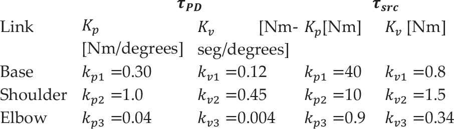
Figure 3 contains the experimental results of the position errors for the proposed controller τ src corresponding to the base, shoulder and elbow joints.
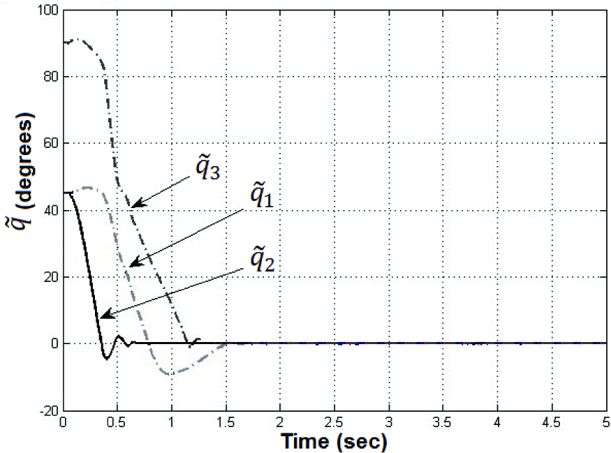
Experimental position errors of the proposed controller
After a smooth transient (t = 1.6 seconds), all the components of the position errors tend asymptotically towards a small neighbourhood convergence of zero; the steady state position errors at time t=2 s have small values of[q˜1(t),q˜2(t),q˜3(t)] T = [0.005,0.004,0.006] T degrees. These errors are present due to presence of static friction at the joints and a lack of static friction compensation in the control scheme.
Figure 4 contains the experimental results of the applied torque for the proposed controller τ src for eachjoint. From the experimental results, these applied torques clearly evolve insidethe prescribed limits shown in Table 1.

Applied torques of the proposed controller τ src .
Figure 5 shows the experimental results of the position errors for the PD control, which evolve slowly until reaching steady state errors of [q˜1(t),q˜2(t),q˜3(t)] T = [0.5,0.4,0.6] T degrees. It is worth noticing that the transient state requires more time than the proposed controller. Additionally, the torque signals are inside the limits from the actuators.

Experimental position errors of the PD algorithm.
The proposed controller has the property of quickly driving the position error to zero. This feature is due to its square root structure, since the position error is driven as an exponential function, the applied torque is as high as is required and this makes the control action faster, holding the actuator torque constraints thorough the saturating limits.
The
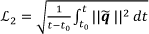
Where t,t0 ∈ ℝ+ are the initial and final times, respectively. A smaller
The main results are summarized in Figure 6, which includes the performance indexes for the τ

Indexes of performance for the evaluated controllers.
6. Conclusions
In this paper we introduced a new control scheme for the position control of robot manipulators. The proposed scheme leads to a closed-loop equilibrium point which is supported by stability analysis - in the sense of Lyapunov - and established conditions for ensuring global regulation. Such a stability proof is important in guaranteeing the suitable operation of the robotic system.
The proposed controller has a bounded smooth response such that the applied torques are inside the prescribed bounds of the servo actuator; with this controller we attempt to retain to a certain degree, the advantage of a bounded signal to overcome the saturation problems of control schemes.
For the purpose of stability, the tuning procedure for the new scheme is sufficient to select a proportional gain as diagonal positive definite matrix and a derivative gain as a positive definite matrix. The tuning up for proportional and derivative gains was chosen such thatKpi < |τ i max | for i = l,2,3; and k vi << kpi.
The efficiency of the proposed scheme was corroborated through experimental tests on a real robot and good results were obtained. The performance of the proposed controller was compared with a PD control in a real-time experimental comparison on a three degrees-of-freedom direct-drive robot manipulator.
From experimental the results, the proposed scheme showed better performance, the response was smoother and without oscillations and the position error was zero due to its square root structure. Since the position error is driven as an exponential function, the applied torque is as high as is required and this makes the control action faster, holding the actuator torque constraints thorough the saturating limits. In contrast, the simple PD was observed to be less robust than the square root-type controller. The proposed controller represents an attractive scheme for the position control problem and applications in point-to-point control and pick-and-place.