
Abstract
Previous research on mobile robots has been based on models of mobile robots with invariant weight parameters. However, the most practical mobile robots that bear heavy burdens have varying weights and centres of gravity. This paper suggests a design for an adaptive PD controller that estimates and adapts to the weight-related parameters of robots that bear varying heavy burdens. Using the suggested adaptive PD controller, the motion of mobile robots can be independent of the weight-related parameters and the operational performance is confirmed by target tracking simulations.
1. Introduction
Robots can be roughly divided into two categories: industrial robots and service robots. A few years ago, most robot applications were built as industrial robots, which were related to the industries and manufacturing. However, interest in service robots is increasing and various service robots have been developed and demonstrated [1–11]. Building service robot systems is not only an interesting scientific challenge but it also provides a practical and realistic effort to improve the convenience and comfort of the lives of humans.
As assistive technologies for improving the quality of human life, service robots should be able to bear heavy burdens, since many tasks are likely to be associated with carrying or handling such loads. However, most of the previous research on mobile robots has not considered changes in the weight-related parameters of the robot. Mobile robots - such as shopping cart robots - have varying weights and centres of gravity, and the movement of the robot is dependent on these parameters. The previous research, however, has assumed that both the robot's weight and its centre of gravity are fixed [11–14]. Furthermore, most of the previous studies have applied robot models that only consider kinematics, not dynamics, to control wheeled mobile robots [15–18]. Such models are inappropriate for mobile robots bearing varying heavy burdens.
Target tracking constitutes one of the most important problems for the mobile robot. The techniques for the target tracking problem can be applied to a number of applications using the mobile robot, such as traffic control systems [19, 20], formation control systems [21, 22] and autonomous robot systems [23]. In order to improve the performance of target tracking, the controller of the robot should be able to control the forward and rotational velocities effectively, regardless of varying weight-related parameters. However, the control performance of the typical controller is related to the varying weight-related parameters. If the weight of the robot is increased, the motors of the robot should be operated with increased power.
This research suggests how to design a controller for mobile robots that bear varying heavy burdens. The robots should be able to follow their target well, even if the robots do not have any information about the weight and centre of gravity of the burden. This research adopts a dynamics model and an adaptive control method which considers varying weight-related parameters and attempts to design a control system which enables consistent movements and the performance of a robot even with changing or shifting parameters.
The organization of the research is as follows: Chapter II presents the design of the motion control system; Chapter III proposes the weight-independent robot control method using the adaptive PD controller; Chapter IV verifies the performance of the controller through simulation; finally, Chapter V provides a conclusion.
2. Design of a Mobile Robot for Motion Control
The mobile robot system in this paper consists of three parts: the human position detector, the robot and the robot controller, as shown in Fig. 1. The major technique of the human position detector is indoor localization, which can be implemented by vision processing and sensor networks. Based on these techniques, the human-robot position detector estimates the positions of the human (i.e., the target) and the robot, and outputs these position variables to the robot controller. The robot controller, which is given the target and robot positions from the human-robot position detector, consists of a path planner, an obstacle avoider and a motor controller. Based on the detected target and robot positions, the path planner finds a path for the navigation of the mobile robot from the current position to the target position, and the planned path is modified by the obstacle avoider. Most mobile robots operate in non-stationary environments - which consist of changing surroundings - and do not have full information about the surrounding environments, even in familiar environments. To avoid collisions with the changing surroundings, the obstacle avoider modifies the path, which is given by the path planner, referring to the measured sensor values
This paper focuses on the design of the motor controller and suggests a new design method for an adaptive PD controller for weight-independent motion control.

The block diagram of the whole mobile robot system for motion control
2.1. Design of a path planner and obstacle avoider for a robot controller using the potential field method
When the robot controller is given the positions of a human and the robot, the robot controller should be able to drive the robot towards the position of the human. The path planner of the robot controller generates the path from the robot to the human and the obstacle avoider modifies the path to avoid collisions between the robot and surrounding obstacles. The path planner and the obstacle avoider are designed based on the potential field method (PFM). The potential field method is the most favoured and widespread on-line obstacle avoidance method for mobile robots because of its computational simplicity and efficiency.
In the potential field method, the motion of the robot is controlled to follow the direction of the artificial force

where

Obstacle avoidance using the potential field method
The path of the mobile robot can be described as an array of several sub-goals and the attractive force
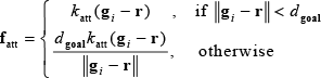
where
The obstacle avoider of the robot controller determines the repulsive force

where n is the number of surrounding obstacles,

where
2.2. Dynamic model of the mobile robot
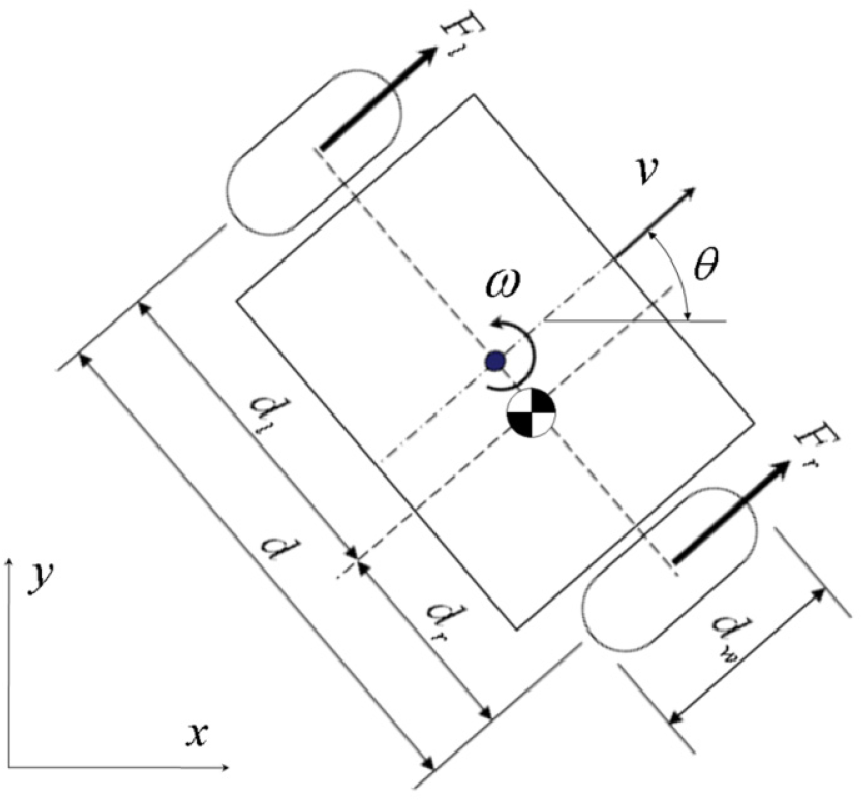
Most mobile robots are developed in the form of wheeled mobile robots, and Figure 3 illustrates a two-wheeled mobile robot and its various parameters. Unlike the previous studies, which placed the robot's centre of gravity along the central axis, this research assumes that the robot's centre of gravity could shift closer to either the right or left wheel. The distances between the robot's centre of gravity and the centre of the two wheels are
The dynamic model of the mobile robot and the control parameters
The robot's location is defined as the robot's centre of gravity, which is plotted on the x-y coordinates. The direction of movement is θ, an angle to the x axis. As for the dynamics parameters, the forward and rotational velocities are v and ω respectively. The following describes the full mathematical model of the robot:
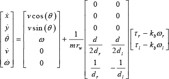
Here,
2.3. Control architecture of the motor controller
This sub-section addresses the control architecture of the motor controller. The input of the motor controller, i.e., the artificial force
The inputs of the motor controller in this paper are the position errors of the robot on the x-y coordinates, and the outputs are the torque values for the two motors of the mobile robot. Based on this outline, the whole control architecture of the motor controller is designed as shown in Fig. 5.

Reconstructed block diagram of the mobile robot system
From (1), we can see that the x-y position and direction of the robot are changed by the value of the forward and rotational velocities and that these velocities are changed by the torque of the two motors. That is, the kinematical factors of the robot can be controlled by the forward and rotational velocity control and these velocities can be controlled by the torque control of the motors. As a result, the main components of the motor controller include a kinematic controller and a dynamic controller. The kinematic controller uses the robot's kinetic errors as an input to yield the robot's forward and rotational velocities for control. The dynamic controller uses the discrepancy between the robot control value from the kinetic controller and the actual movement of the robot. Based on the discrepancy, the dynamic controller decides the torque of each motor using a PD control method and controls the actual motors of the robot.

Control architecture of the motor controller
2.4. Design of the kinematic controller
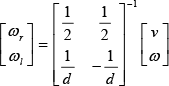
The kinematic controller has three inputs (

The transformation from the position errors to the velocity errors
As addressed previously, the input
When the unit vector pointing toward the heading direction of the robot is:

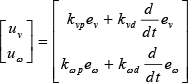
the forward velocity error

The forward velocity error

From (8) and (9), the position errors

where the values of
2.5. Design of the dynamic controller using the PD control method
In this section, a PD controller that does not consider weight factors is designed. In the subsequent section, an adaptive PD controller is designed by correcting the motor torque due to changes in the robot's weight and centre of gravity.
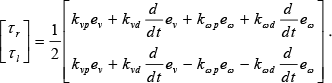
The PD controller operates on a multi-input-multi-output system. The input value is the discrepancy between the target and the actual acceleration values for forward and rotational movement, and the output value is the torque of the two motors. The PD control values are calculated for both forward and rotational acceleration and converted to motor torque values. Equation (5) describes the PD control value for errors
The values of

Substituting (11) into (12), the overall dynamic controller with the PD control can be rewritten as:
3. Weight-Independent Robot Control Using an Adaptive PD Controller
The weight-independent motion control of the mobile robot can be enabled by considering weight-related parameters m and
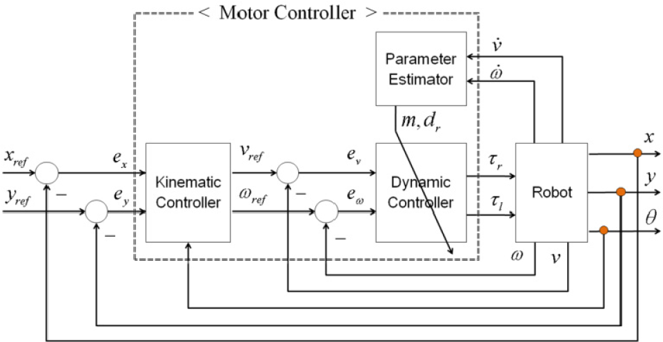
Control architecture of the mobile robot control system using the adaptive PD controller
3.1. Design of the adaptive PD controller
From (5), the state equations that describe the relations between the accelerations and the torque of the robot can be rewritten as:

Equation (14) shows that the amount of the forward and rotational accelerations will be changed by the change of the weight-related parameters m and
Whatever the values of the weight-related parameters m and

where the constants
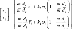
Equation (16) transforms the torques
According to (16), if the actual weight-related parameters m and

where:

3.2. Parameter estimation using a recursive least square (RLS) algorithm
To ensure the sound performance of the adaptive PD controller, the parameter estimation needs to be accurate. The research applied the recursive least square method for a parameter estimation algorithm:

where:

The renewal of the information matrix is done as in (22):

and the renewal of the estimated parameter values is done as in (23):

whereby:

The initial parameter estimate value is set as a standard parameter value, as shown here:

4. Simulation
This chapter verifies the performance of the proposed control system via a simulation and all the parameters of the robot system are determined in Table 1. The simulation was carried out in MatLab R2009a.
Definition of Parameters

In simulation, the robot begins in the lower-left corner and tracks the target (human) that moves at a rate of 0.5m/s in rectangular pulses, as shown in Figs. 10(a)-(c). In order to check the performance of the proposed controller, the simulations are executed in three target tracking systems, as shown in Figs. 10(a)-(c). The trajectory of Fig. 10(a) is when the weight-related parameters m and

Change of the weight-related parameters m and
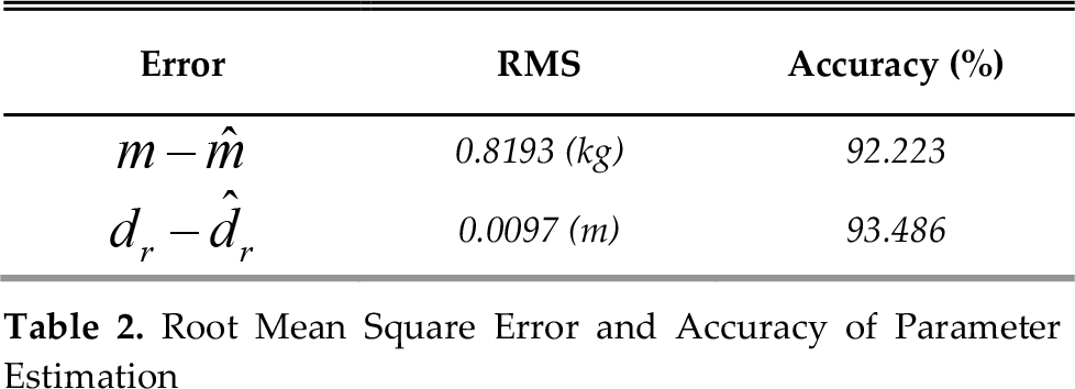
The performance of the proposed adaptive PD controller depends on the performance of parameter estimation. If the parameter estimator estimates the varying weight-related parameters m and

Errors between the actual and the estimated weight-related parameters
Root Mean Square Error and Accuracy of Parameter Estimation

Outcome of target tracking with or without change in weight and the centre of gravity: (a) PD control without parameter change, (b) PD control with parameter change, (c) adaptive PD control with parameter change, (d) distance errors between the trajectories with and without parameter change
The trajectory of Fig. 10(a) can be a standard of performance for target tracking. The result of Fig. 10(d) shows the distance errors of the robots using the conventional PD controller and the adaptive PD controller, compared to the trajectory of Fig. 10(a). As the weight-related parameters change, the trajectory of the robot using the PD controller is significantly changed. The adaptive PD controller, however, yields an outcome as if the weight-related parameters had not been changed. Moreover, the difference in performance between the conventional PD controller and the suggested adaptive PD controller are shown clearly in Fig. 10(d). The trajectory of the robot using the adaptive PD controller changes below only 0.08m, even with changing weight-related parameters. The root mean squares of the distance errors between the trajectories with and without parameter change are shown in Table 3. The root mean square error for the proposed adaptive PD controller is about 19.29 times smaller than that for the conventional PD controller. As a result, the mobile robot can be controlled weight-independently using the proposed adaptive PD controller.
Root Mean Squares of Distance Errors

5. Conclusion
Based on a dynamic model that takes into account the varying weight and centre of gravity of a robot, this research designed an adaptive control system to ensure the consistent performance and movement of a robot under varying weight-related parameters. The research results could be applicable to all mobile robots with varying weight parameters, e.g., robots equipped with manipulators that load or unload cargo. A manipulator's centre of gravity is bound to shift due to its movement, and when it loads or unloads cargo the weight imposed upon the robot changes as well.