
Abstract
This paper overviews some author's biomechanical inspiration for the development of an approach which enables the realization of bipedal artificial motion. First, we introduce the notion of dynamic balance, which is a basic prerequisite for the realization of any task by humanoids. Then, as ground reference points, important indicators of a humanoid's state were introduced and discussed. Particular attention was paid to ZMP, which is the most important indicator of robot dynamic balance. Issues of modelling of the complex mechanical systems (humanoids belonging to this class) were also discussed. Such software should allow humanoid modelling, either without any contact with the environment (such as flying freely in space, for example, during jumping) or having contact with ground or any other supporting object. It also should be enough general to cover different humanoids' structures, postures, and allow the calculation of all relevant dynamic characteristics. Some examples are presented in this paper (e.g., the modelling of a goalkeeper catching a ball, the replication of human motion trying to re-establish posture and dynamic balance where jeopardized by perturbation).
1. Introduction
As defined in [1] “Biomechanics 1 is the study of the structure and function of biological systems by means of the methods of mechanics.” However, in engineering we often want to build up a replica of a biological system, imitating its “natural” behaviour and trying to make the replica as close as possible 2 to its biological paragon. To achieve this engineering has to be bio-inspired. There are many examples where design has been inspired by biological systems, but we will focus on humanoid robots and, in particular, biped locomotion.
Let us begin with history. Concepts akin to today's robot can be found as long ago as 450 B.C., when the Greek mathematician Tarentum [2] postulated a mechanical bird which he called “The Pigeon” and which was propelled by steam. Al-Jazari (1136–1206), a Turkish [2] inventor, designed and constructed automatic machines such as water clocks, kitchen appliances and musical automatons powered by water. One of the first recorded designs of a humanoid robot was made by Leonardo da Vinci [2], around 1495. Da Vinci's notebooks, rediscovered in the 1950s, contain detailed drawings of a mechanical knight able to sit up, wave its arms and move its head and jaw. The first known functioning human-like robot was created in 1738 by Jacques de Vaucanson [2], who made an android that played the flute, as well as a mechanical duck that reportedly ate and defecated. In 1893, George Moor [2] created a steam man. He was powered by a 0.5 hp gas fired boiler and attained a speed of 9 mph (14 km/h). Westinghouse made a humanoid robot known as Electro. It was exhibited at the 1939 and 1940 World's Fairs. It is also important to mention another not so well known scientist, Nikolai Aleksandrovich Bernstein [3]. He began his research at the beginning of the 1920s by studying voluntary movements. At that time, he significantly refined the classic methods of recording movements [4, 5], and already in 1926 his first book “General Biomechanics” [6] came out. He made a significant contribution to the study of biomechanics and especially of the modes of human motion, such as walking and running. Moreover, Bernstein was the first in world science who studied motion from the viewpoint of the knowledge of the regularity of brain functioning. While the scientists before Bernstein studied human motion with the objective of merely describing it, Professor Bernstein began the study of this motion to establish how it was controlled [7–12]. He thought that a researcher who wants to understand the brain's functions could hardly find a more worthwhile object for such study than by controlling movement.
The most important bio-inspired notion regarding biped locomotion is the Zero-Moment Point (ZMP), which was first introduced by Vukobratovic and his associates [13–19]. The first application of the ZMP was made by Japanese researchers in the middle of the 1970s, headed by the late professor Kato. At Waseda University, they developed biped WL 12 which, for the first time in the world, performed fully dynamic walking [20]. Later on, there were a number of examples of biped walking robots using ZMP as a basis for gait realization: e.g., Wabian [21] and Asimo [22, 23]. Let us also mention example of first exoskeletons for the restoration of walking function [24].
2. Ground reference points and dynamic balance
2.1 General – the notion of dynamic balance
In this paper, we will try to demonstrate the biomechanical inspiration for the development of an approach which enables the realization of biped artificial motion (posture realization, gait synthesis and realization). In all these activities, the maintenance of a humanoid upright position (i.e., dynamic balance) is a task that is constantly present during any kind of motion and, thus, of basic importance for any kind of humanoid activity while standing. This is why we will first pay attention to this extremely important issue.
The motion of bipedal robotic systems is realized by a synchronized motion of the joints in robot's legs, arms and trunk – i.e., by the change of the robot's internal coordinates. The validity of the motion performed is verified with respect to the environment (external coordinates). In order that the preset goals can be realized by the humanoid system's motion, a unique and bidirectional correspondence must exist between the movements performed in internal (joint) coordinates and their external effect regarding the environment – i.e., between internal and external synergies. In other words, the action realized by the moving robot's mechanism joints will attain the goal if the mechanism is “properly” supported. This notion of “proper contact with the ground” needs clarification.
Let us focus on the humanoid robot sketched in Fig. 1. [25]. Let the coordinate frame representing the environment to which external synergy has been defined be xGR OGR zGR (Fig. 1a) and let it be fixed to the ground. Also, let the internal synergy be defined with respect to the coordinate frame xF OF zF fixed to the foot tip (Fig. 1a). Both coordinate frames are presented only in the sagittal plane (the y-axis not being shown in either of the cases).

Illustration of the relationship between internal and external synergy.
Let us further suppose that the humanoid is walking (Fig. 1 shows the single-support phase) while trying to reach the object O shown in Fig. 1b. The object position requires that the hand tip (represented by the point H) approaching the trajectory is parallel to the x-axis of the frame xF OF zF. In case, the foot realizes “proper” contact with the ground (i.e., contact over the surface, not the line or the point) and the coordinate frames xGR OGR zGR and xF OF zF will coincide while hand trajectory will also be parallel to the x-axis of the external coordinate frame xGR OGR zGR. Suppose further that a disturbance occurred and that the humanoid started falling forward by rotating about the front foot edge (Fig. 1d). In such a case, the frames xGR OGR zGR and xF OF zF will not coincide any more (Fig. 1e). They are being rotated by the angle φ. If the humanoid is continuing to realize the joints' trajectories exactly as before, the occurrence of the disturbance of the hand trajectory will remain parallel to the x-axis of the frame xF OF zF but will not be parallel to the x-axis of the external frame xGR OGR zGR. In other words, in the case of any “non-proper” foot-ground contact, the internal and external synergies will not coincide. This means that now the hand trajectory with respect to the environment (external synergy) will not depend solely on the joint angles qi, i=1, … n but also on the angle φ between the foot and the ground. We think it is obvious that this non-coincidence of the hand trajectories is caused by the foot rotation relative to the ground and that it influences the behaviour of the overall system. Thus, we can say that in the case of biped locomotion a unique relationship between internal and external synergies is ensured by the relative immobility of the robot's foot (more precisely, the legs' terminal links 3 ) and the environment in contact. If this holds, the robot is dynamically balanced. This means that if a proper internal synergy results in the proper external synergy, we say that the robot is dynamically balanced or, more specifically, that dynamic balance can be represented by the relative immobility of the coordinate frames xGR OGR zGR and xF OF zF representing internal and external synergies.
As the contact with the ground is realized through the feet, this means that “proper” contact with the ground requires that the terminal link of the supporting leg(s) 4 does not move with respect to the ground. Since the contact between the foot and the ground is unilateral (there is no constraint or resistance to prevent a foot lifting from the ground), it is necessary that the biped during motion does not generate forces that would cause the turning of the foot about its edge.
2.2 Ground reference points
2.2.1 CoP, MCP, and ZMP
Let us look more closely at the notion of dynamic balance [26]. It is clear that any change of the system dynamics will cause a change in any reactions between the foot and the ground. Let us first consider a static single-support case – a robot “standing upright” on one leg, without moving – and let the resultant of the gravitational forces pierces the ground plane at a point which is inside the support area. The piercing point is called the centre of pressure (CoP). Looking from the opposite direction, one may say that the CoP is the point where the resultant ground reaction force pierces the supporting surface. The condition that the CoP is inside the support area guarantees the static balance. In addition, in static case this condition means that the centre of mass projection (CMP) is inside the support area (edges excluded).
Now suppose that the humanoid starts to move, still relying on one leg. As an examples, one may might imagine a gymnastic exercise or a single-support phase during walking. In this dynamic case, and in addition to the gravitational and external forces, there also appear inertial forces generated by the robot's motion. The piercing point now concerns the resultant of all the forces: gravitational, external, and inertial. For the piercing point (CoP), it holds that the sum of all moments about around two horizontal axes equal zero. If the piercing point is within the support polygon (excluding the edges) it is called the Zero-Moment Point (ZMP); note that in this case, the ZMP and the CoP are actually the same point. If so, we say that the system is dynamically balanced – the foot maintains its surface-to-surface contact with the ground. If, however, the piercing point finds itself on the edge, indicating that the foot is turning, then the term CoP still applies while the ZMP is not used. The system is no longer dynamically balanced and the surface-to-surface contact is replaced by a line (or point) contact. So, the term ZMP is reserved for dynamically balanced biped's states.
2.2.2 Double support posture – ZMP related to CoPleft and CoPright
While notions of ZMP and CoP look quite similar in the above described single-support situation, the difference being almost formal, their true relevance and the difference will become fully apparent when the double-support situation is considered. Bearing in mind that statics is just a special case of dynamics, we move our attention immediately to a dynamic double-support problem. Suppose that a humanoid performs some movement while supported on both feet. As examples, one may imagine a double-support phase of walking or some appropriate actions in sports (karate, gymnastics, etc.). Regarding the ground reaction forces and the centre of pressure, one has to distinguish between two foot-specific points, one defined for the left foot and the other for the right foot: CoPleft and CoPright. The role of these two points is to indicate the kind of contact existing between a particular foot and the ground. If CoPleft is inside the contact area of the left foot, excluding edges, the foot keeps its surface-to-surface contact with the ground. If, however, the point finds itself on the edge, it means that the foot starts turning. An analogous discussion holds for the right foot. While with the single-support posture for the turning of the foot means that the posture was compromised, the double-support posture is much more flexible. If one or both feet start turning, the posture need not be “lost”. To explore this, we use the ZMP concept. Since the ZMP is defined above as the point inside support area where the resultant moments of external and inertial forces about two horizontal axes equal zero, it is a unique characteristic point representing motion of the whole robot. The ZMP is not foot-specific but rather is related to CoPleft and CoPright, as shown in Fig. 2. To conclude, the ZMP is the indicator of dynamic balance. If it is within the convex support polygon created by the feet (the grey area in Fig. 2), we say that the humanoid is dynamically balanced. If the ZMP comes to the edge of the support area, the balance will be lost and the entire robot will start falling down, overturning about the edge.

Relation between the ZMP and the foot-specific CoP points in the double-support state.
Fig. 3 shows how the support area changes during the double-support phase of the regular bipedal gait. Figure 4 presents two examples of an irregular gate. In case (b), a man has a wounded sole, and thus can only support just himself on the outer edge of this foot. Case (a) shows a more seriously injured man who walks with a crutch. In both cases, there exists a supporting area offering the possibility of dynamic balance in the double support phase. The common characteristic of these irregular gaits is that the left and right single-support phases will not be symmetric. When the healthy right foot is on the ground, the support area will exist and the dynamic balance will be likely. However, when supporting on the wounded left foot or the crutch, the area will disappear, reducing to a line or a point, and thus preventing any possibility of balance. This situation is not so uncommon with humans and it is overcome in the way that unbalanced and thus partly uncontrolled motion is seen as acceptable if re-establishing the balance and full control is expected in the next double-support phase when the deviation will be corrected.

Double-support phase of the gait. It starts with the heel strike – (a). If we adopt single-link feet, the overall shaded zone shows the support area created by the entire rear foot and the heel of the front foot that has just ended the swing phase and landed. In the case of two-link feet, the double-support phase also begins also with the heel strike, but the rear foot is in contact with the ground by its toe link only. The support area is now shown as darker shaded. Later, the entire front foot will contact the ground, – as shown in (b),) – thus enlarging the support area. The overall shaded area shows the support if the feet are of a single-link type. The darker shaded zone represents the support area for the two-link feet.

Two examples of an irregular gait. (a) The right foot makes the full contact while the left leg is replaced with a crutch making a point contact.(b) The right foot is in full contact and the left one makes a line contact.
Let us point out that ZMP is an instant indicator of dynamic balance – it can answer whether a system is balanced or not at the current time instant but it cannot say whether it will maintain the balance in the immediate future. Let us illustrate this by example, where the a humanoid is walking fast when suddenly the need to stop arises. If the momentum is large, the generated inertial forces (due to the deceleration while stopping) may cause the loss of the dynamic balance.
The further generalization of the ZMP notion can lead to different complex human/humanoid motions, like as in sports. One can imagine a posture where a gymnast stands on his head and hands while the his legs are up. Clearly, there would be three CoP points and a unique ZMP defining the dynamic balance.
Mathematically, the ZMP can be defined in several ways. Consider a Cartesian frame with the x and y axes being tangential to the flat ground and the z-axis being normal. For a dynamically balanced bipedal walker, there is always a unique reference point for which it holds that:

where summation is made for all the moments generated by the ground reaction forces, arising from the foot-ground contacts. For a dynamically balanced system, this point is inside the support area and is called the ZMP. Therefore, the ZMP represents the point where the resulting reaction force acts (if the ZMP is positioned between the feet, the total ground reaction force is a sum of two reaction forces under the feet and formally acts as the ZMP). The ZMP position inside the support area (excluding the edges) guarantees that the system will not rotate about the edge of the support region.
Alternatively, instead of summing up the forces “under” the contact surface (i.e., the reaction forces), one may sum the forces “above” the contact. The ZMP is then thought of as that point inside the support area at which the sum of moments due to all forces (gravitational, forces induced by the mechanism's motion, and external forces, if they exist) has no component along the horizontal axes. This is mathematically described by above expression, where Mx and My are now interpreted as the moments of all acting forces.
The ZMP, as a function of the centre of mass (CM) position, the resultant inertial force, and the resultant inertial moment about the (CM), can be expressed and calculated as:
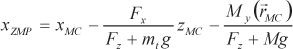

where mt is the total mass; Fx and Fy are the components of the resultant inertial force (given above); and are the components of the resultant inertial moment about the CM, and g is the gravitational constant.
In the single-support phase of the gait (only one foot is in contact with the ground), the ZMP obtained by Eq. (1) refers to the supporting foot and its contact area. Its existence in the support region (excluding the edges) prevents turning about the edge of the foot. In the double-support phase, the support area is enlarged and it can be done in many different ways.
Note that the ZMP and the CoP actually represent the same point while located inside the support area (excluding the edges), – i.e., while the system is in dynamic balance. If this point reaches an edge, turning about the edge will begin and the dynamic balance will be lost. The system dynamics radically changes since a new degree of freedom appears. Accordingly, the calculation of the dynamics must switch to the appropriately modified model. The term ZMP is exclusively used for dynamically balanced states and can not be applied for collapsing biped. The CoP will keep its location on the edge while the foot is turning. If the calculation finds the ZMP out of the support region, this means that the algorithm was too rough to precisely indicate the moment when the ZMP reached the edge and thus missed to switch to the modified dynamic model. More details can be found in [25, 26].
2.2.3 CMP
The Centroidal Moment Pivot (CMP) [27–32] is a ground reference point whose position defines the existence of the moment acting about the system's mass center CM. The CMP location,

When the CMP departs from the ZMP, there exist nonzero horizontal CM moments, causing variations in whole-body angular momentum. While the ZMP cannot leave the ground support area, the CMP can, but this will happen only when horizontal moments act about the CM.
The zero CM moment (ZMP = CMP) is not a general feature across all human movement tasks. For some movement patterns, humans purposefully generate angular momentum to enhance stability and manoeuvrability [31–33]. By actively rotating body segments (arms, torso, legs), CM moments can be generated which cause horizontal moment forces to act on the CM. This strategy allows humans to perform movement tasks that would not otherwise be possible. For example, while balancing on one leg, humans are capable of repositioning the CM just above the stance foot from an initial body state where the CM velocity is zero, and the ground CM projection is outside the foot support envelope.
3. Dynamic model of general human/humanoid motion
3.1 The concept
In the above discussion on of the ground reference points, we tried to make their definitions general. Previously, the reference points were introduced to allow for the modelling and synthesis of the bipedal robot gait. Accordingly, their application was based on dynamic models restricted to walking. However, the relevance of the reference points goes beyond this application. They actually apply to any humanoid motion and any kind of ground contact: running and jumping, gymnastic exercises, other motions in sports, posture analysis, etc. To exploit such possibilities and apply the reference points in such a general way, we need the a dynamic model which is sufficiently universal to cover any humanoid motion task. The method presented in [34–36] and proposed for sporting motions in [37] offers a solid foundation for this. The contact analysis, – essential in this method, – follows the theory explained in [38].
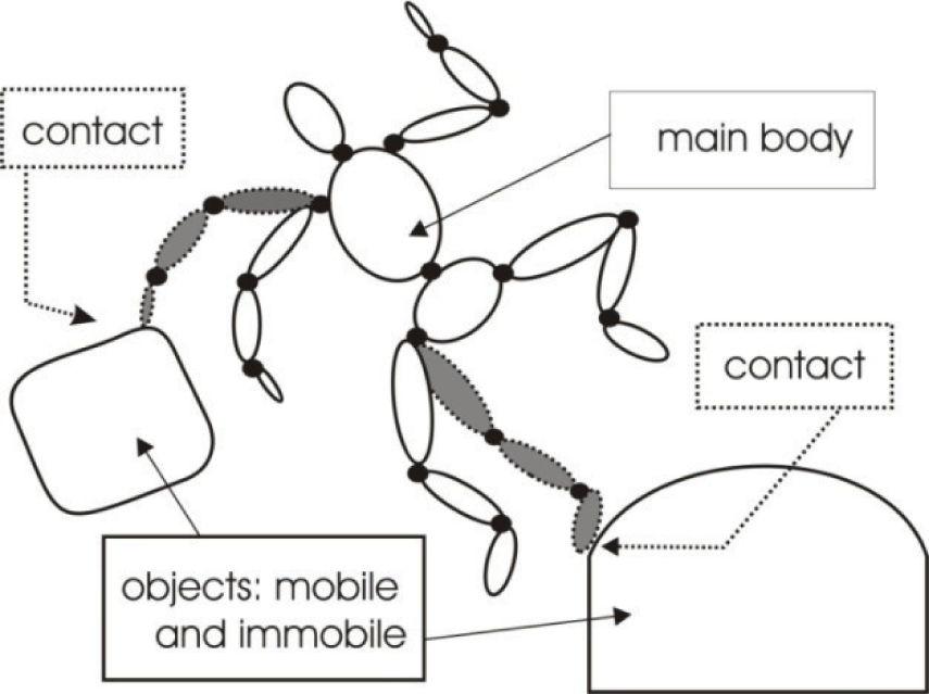
The proposed general approach starts by considering a humanoid that “flies” without constraints (meaning that it is not connected to the ground or to any object in its environment – see Fig. X1). The term flier is suggested. Such a situation occurs in running, jumping, trampoline exercise, etc., but it is less common than the situation where the human-humanoid is in contact with the ground or some other supporting object.
Let us introduce the contact of the flier and some external OBJECT (the term object includes the ground). A contact can be rigid or soft. With a rigid contact, one LINK (or more of them) of the flier is geometrically constrained in its motion. An example is the gait, where the foot is in contact with a non-deformable support. With a soft contact, there is no geometric constraint imposed on the system motion, but the strong elastic forces between the contacted link and some external object make the link motion close to the object. An example of such contact is walking on a support covered with an elastic layer. In view of limitations, we restrict our consideration to the rigid case.
3.2 Mathematics
3.2.1 Free-Flier Motion
We consider a flier as an articulated system consisting of the a basic body (the torso in this case) and several branches (head, arms and legs), as shown in Figure 6. Joints have one degree of freedom (DOF) each. Let the joint angles be described by the n-vector:


The CMP and the relation between the ZMP and the CMP.
Unconstrained (free flier) and constrained systems
We now consider the drives. It is assumed that each joint has its own drive – the torque τ
j
. Note that, in this analysis, there is no drive associated to with the basic-body coordinates
The dynamic model of the free flier has the general form:
or

The dimensions of the inertial matrix and its submatrices are:
3.2.2 Contact Motion
Let us consider a LINK that has to establish a contact with some external OBJECT. In example of walking, it is the foot moving towards the ground and ready to land (in walking or running). In the example of a soccer game, one may consider the foot or the head moving towards a ball in order to hit. The external object may be immobile (like the ground), an individual moving body (like a ball), or a part of some other complex dynamic system.
In order to express the coming contact mathematically, we introduce relative coordinates
A consequence of the rigid (no elastic deformation) link-object contact the link and the object move, along certain axes, together. These are constrained (restricted) directions. Let there be m such directions, m being a characteristic of a particular contact. The relative position along these axes does not change. Along other axes, relative displacement is possible. These are unconstrained (free) directions. In order to get a simple mathematical description of the contact, s-coordinates are introduced so as to describe relative positioning. A zero value of for some coordinate indicates existance of the contact along the corresponding axis. For a better understanding, we use a well-known example (Figure 7) coming from a biped gait.

Foot-ground contact in a bipedal gait: (a) heel strike phase – woman's shoe with a high heel; (b) heel strike phase – rectangular robot foot; (c) “flat foot” phase of the gait; (d) foot overturning due to lost balance.
We show the motion of the foot after the “heel strike”. Case (a) is the motion of a woman's shoe with a high heel. Case (b) is a rectangular robot foot. Later, the “flat foot” phase of the gait will constrain all six foot coordinates (case (c)). However, if the foot begins to turn about its edge, like as in the case of lost balance (case (d)), a free coordinate will appear again (coordinate Ψ in the figure).
The motion of the external object (to be contacted) has to be either known or calculable from the appropriate mathematical model, and then the s-frame fixed to the object is introduced to describe the relative position of the link in the most appropriate manner. Thus, in a the general case, the s-frame is mobile. As the link is approaching the object, some of the s-coordinates reduce and finally reach zero. The zero value means that the contact is established. These functional coordinates (which reduce to zero) are called restricted coordinates and they form the subvector

where
The relative s-coordinates, depend on link motion (thus on the flier motion

When speaking about a moving object, one may distinguish between two cases.
The first case assumes that the object motion is given and cannot be influenced by the flier dynamics. An immobile object is included in this case. Such a situation appears if the object mass is considerably larger than the flier mass (thus, the flier influence may be neglected), or if the object is driven by so strong actuators that they can overcome any influence on the object motion. An example would be walking on the ground, – i.e., contact between the foot and the ground. The ground is the large immobile object. Another example is walking on a large ship. The ship is a large object whose motion is practically independent of the walker. The ship is a dynamic system but it cannot be influenced by the walker, and so, from the standpoint of the walker, the ship motion may be considered as given. Accordingly, one may say that
The other case refers to the object being a “regular” dynamic system, so that the flier dynamics can have an effect on it. The example would be walking on a small boat. The boat behaviour depends upon the motion of the walker. Here, the time history of
The relation (6) can be written in the second-order Jacobian form (separation (x3) included):


The dimensions of the Jacobian matrices are:
Due to space limitation, we restrict the consideration to durable (lasting) contacts. This means that the two bodies (link and object),) – after they have touched each other and when the impact is over, – continue to move together for some finite time. An example is walking. When the foot touches the ground, it maintains contact for some time before it moves up again.
The contact-dynamics model is obtained by introducing contact reactions into the free-flier model (4). Reactions appear along the restricted directions

Due to the m-component reaction
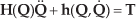
The rigid contact is described by the m-dimensional condition

Now, relations (9) and (10) involves N+m scalar equations. Let us list the unknowns: N scalar unknowns in

Now, (9), (10), and (11) describe the dynamics of a flier-plus-object contact motion, allowing one to calculate the accelerations
Under some of the conditions discussed above, the object model (11) can be considered as to be independent of the flier dynamics. Accordingly, it can be solved separately and the solution used to resolve the flier model (9), (10).
3.2.3 Impact
One may might recognize the three phases of a contact task: approaching, impact, and regular contact motion.
Approaching means that the link moves towards the object. From the standpoint of mathematics, approaching is an unconstrained (and thus free) motion. Although all of coordinates from the vector
The flier dynamics during approaching is are described by the model (4). The model represents the set of N scalar equations that can be solved for N scalar unknowns – the acceleration vector
Let us discuss the desired (reference) motion
During the approaching phase, the integration of the system coordinates
In the case of a rigid impact, there exists a finite or infinitely short period while the system velocities change so as to meet the geometrical constraints imposed by the contact – this is the impact interval. Let it be [t'
c
, tc“]. At t'
c
approaching finishes and at t“c the regular contact motion described by (9), (10), and (11) starts. The shorter the impact interval, the higher the impact forces. For this analysis, we adopt the an infinitely short impact: Δt = t”c – t'c → 0. Hence, infinitely high impact forces are expected. Next, we assume a plastic impact (the durable contact mentioned above) where the connected bodies maintain contact for some finite time, moving together. Finally, we assume that all the m coordinates forming
We now integrate the dynamic models (9) and (11) over the infinitely short impact interval Δt, thus obtaining:

and:

where:

The system state at the instant t′c, (i.e.,
Now, the model (12),) and (13) contains N + Nb scalar equations with N + Nb + m scalar unknowns: the change in velocities across the impact, Δ

The augmented set of equations, (12), (13) and (15), allow us to solve the impact. The change Δ
3.3 Simulation Experiment
In order to support the potentials of the proposed general method, we present the results of the simulation of a complex sporting motion – e.g., a soccer goalkeeper's action. Figure 8 shows the snapshot of the action.
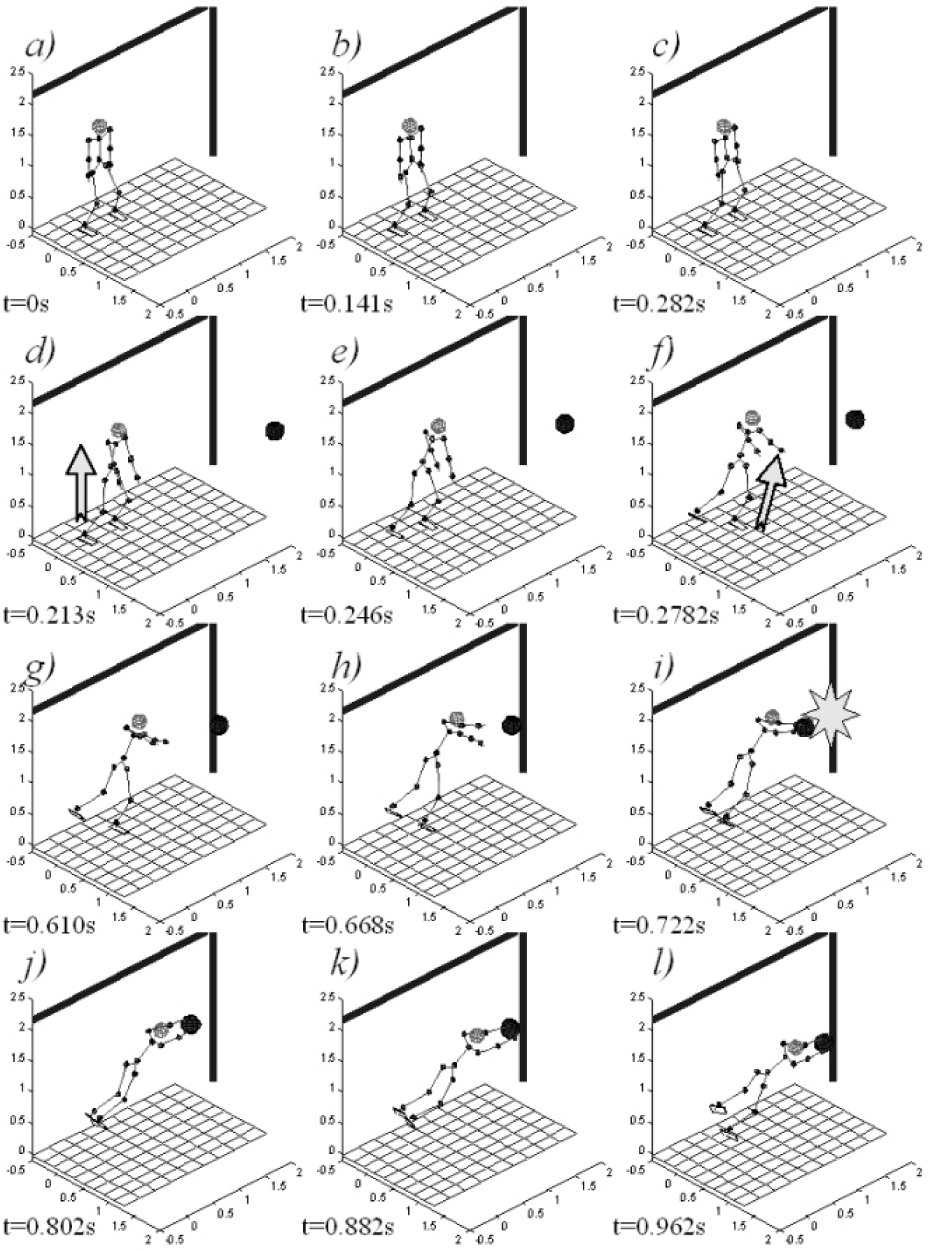
The sSnapshot of the human/humanoid goalkeeper motion.
The following phases can be distinguished in this example.
In
When the left foot leaves the ground (at t = 0.2782s, Figure 8 f),)
Falling down represents
All of the relevant dynamic characteristics could be calculated, like such as joints and main-body coordinates, joint driving torques, total reactions in joints, impact effects, power requirements, and energy consumptions, etc.
4. Ground reference points – case study
4.1 ZMP control of the regular gait in the presence of disturbances
Under real conditions, the realization of motion is always accompanied by disturbances, and some deviation from ideal (reference) motion always exists. The deviation in tracking reference trajectories at the joints causes the deviation of ZMP from its reference position. An especially undesirable situation arises when the ZMP comes too close to the edge of the support area, – when it might happen that the humanoid loses its balance, – and starts to rotate about the support area edge, and collapsing. The control has to ensure the approaching to the reference trajectories of all the powered joints while constantly preserving dynamic balance.
In order to better comprehend better the complex issues related to control and – later – to defining the stability of humanoid motion, let us consider three characteristic cases due to disturbance effect. In all three cases, it is assumed that the humanoid in the beginning of the considered period performs a reference motion and then disturbances begin to operate.
Due to the external disturbance force (smaller intensity), the ideal tracking of the joint trajectories is disturbed, – as well as the ZMP position, – but so that it still remains within a “safety zone”. Appropriate control actions can return the system to the reference trajectory.
Assume now that a disturbance force of medium intensity is involved. In this case too, the force causes that the ideal tracking of the joint trajectories is to be disturbed, and the deviation of the ZMP from its reference position is increased. To preserve dynamic balance, the humanoid must undertake a “more resolute” action (e.g., arms swinging), in order to enusre ensure that the ZMP remains within the “safety zone” and also to return the system again to the reference motion.
In the case of a high-intensity disturbance, unpowered (passive) DOFs arise, and the system as a whole begins to rotate about the edge of the support area. The attempt to minimize the deviations of joint trajectories and resume reference motion is senseless if the system has lost dynamic balance. Hence, it is of highest interest to preserve (or re-establish) dynamic balance, taking no care at the moment of the joints' trajectories tracking. Because of that, the humanoid has to abandon the realization of the previous reference motion and, for example, step by one leg in the direction of falling, achieve support on it, and – in the few steps – return to the reference trajectory.
In all three cases, the task of control is to minimize the deviations of the real humanoid state from the reference one for all the joints while preserving the dynamic balance, whereby in Case 2) – and especially in Case 3),) – the priority task is to prevent the system from falling (i.e., preserve its dynamic balance).
In practice, small disturbances are most common, so such that the problem of gait control reduces to Case 1), which has been investigated most thoroughly in [39]. Hence, we will not elaborate it in detail and we will instead give only a brief account of it, just for the sake of completeness of our discussion. In this case, the control has to minimize the deviations in all the joints and, when the attained motion is close to the reference one, the real ZMP will be close to its reference position. However, the compensatio-nal actions at the joints have as a side effect the change of the links' accelerations (differing from the reference ones), and this further leads directly to the change of the intensity and direction of the inertial forces (and, consequently, the ZMP position). Thus, by correcting the internal synergy, the external one can be upset. To prevent the appearance of unpowered DOFs, it is necessary to constantly measure [15] the real ZMP position and endeavour to bring it during the motion most closely to its reference position. Information about the ZMP position is fundamental, both for the synthesis of the reference motion (the reference ZMP position) and control of the real motion of the humanoid (the real ZMP position).
In the case of small disturbances, the deviations can be compensated for in two ways:
local feedbacks at each joint attempt to bring the trajectory of the joint motion as close as possible to the reference one, whereby care is taken of the compensation “intensity” (i.e., of the generated accelerations because of which the real inertial forces will differ from the reference ones), in order to avoid the side effect of jeopardizing dynamic balance, and apart from the local feedbacks acting at each joint, an additional task can be assigned to a joint or a group of joints to prevent inadmissible excursions of the ZMP, even at the expense of “spoiling” the quality of the tracking reference trajectories at the joints. Compensational actions to prevent the loss of dynamic balance of the humanoid are defined solely on the basis of measuring the real ZMP position.
Cases 2) and 3) differ from Case 1) only in respect of disturbance intensity; the larger is the disturbance, the more endangered is the dynamic balance. Hence, the most urgent task is to prevent the humanoid from falling and, when this danger is eliminated, the system can turn to minimizing joint deviations and bringing the motion as close as possible to the reference one. Because of that, in the first phase of compensating larger disturbances, the humanoid's part that is not directly involved in the motion (e.g., the arms) has to abandon the tracking of the reference trajectories for a while, and, by an energetic action (e.g., of the arms or the trunk), “ensure” dynamic balance, whereby the legs' links do not significantly change their trajectories. After that, the system switches to the algorithm similar to that described for Case 1), so as to return fully to the reference motion. In other words, part of the system is abandoning the realization of internal synergy in order to prevent overturning and preserve the possibility of walking continuation, and then returns to tracking the external reference synergy.
If the disturbance is of such intensity that it causes the instantaneous appearance of unpowered DOFs and the overturning of the humanoid, then the overall system has to abandon the tracking of internal synergy and attempt to resume dynamic balance, (e.g., to step in the direction of the system's fall, gain support on that leg, re-establish dynamic equilibrium, and, in the next few steps, return to the reference motion [39]).
It should be noted that the disturbance described in Case 3) results in the degeneration of the humanoid-ground contact area to a line or point, and the sensory information about the contact force is lost. The ZMP, then, does not exist. In order to take any decision about a compensational action, even on passing to a new internal synergy, some other sensory information about the relevant coordinates of the instantaneous state of the system is needed, – especially about the relative position of the humanoid in its environment. In a similar situation, a man receives the necessary information from the equilibrium sensors, the visual system, and the like, while in the case of the humanoid, similar information could be obtained either from a gyroscope [21], vision, an inclinometer, etc. In any case, additional sensory information is needed.
4.2 Ground reference points – disturbed motion and its compensation
Following experiment [40] 5 we can introduce additional insight into as to this issue. The basic idea of the experiment was to record “natural” responses of humans on unexpected perturbations, than to replicate, as close as possible, this motion by simulation (please note that control should be appropriately defined and applied); and finally to compare the recorded and simulated motion to verify the applied control.
Healthy adults volunteered for the study. Each participant was asked to stand on his left foot and lean to his left until his shoulder touched a vertical support wall. The support wall was a flat force sensor and the participant was asked to lean until this sensor measured approximately 20 N of force. This level of force corresponded to a leaning posture where the CM projection on the ground surface fell outside the stance foot envelope. The support was then suddenly pulled away and the motion recorded.
The three-dimensional motion of the whole body was recorded by an infrared camera system (the precision of the detecting marker position was ∼ 1mm) and the whole-body CM position was computed from the kinematic data. The ZMP and the ground reaction force intensity were obtained from the force plate (the measured ZMP). The ground reaction forces were measured synchronously with the kinematic data at a sampling rate of 120 Hz using a force platform. The force intensity and its acting point position (the ZMP location) were measured at a precision of ∼0.1 N and ∼2 mm, respectively. However, the position of the ZMP was also computed on the basis of a model of a human and compared with the measured ZMP position.
It should be pointed out that the reordered movement changes significantly from beginning to end and it was not possible to control the system in same way during the whole movement. This was the reason the movement was split into three phases, each having different characteristics. The phases were defined in the following way:
Phase 1 is characterized by the agile motion of the whole body. Here, the primary aim is to preserve dynamic balance – i.e., prevent the fall. This phase begins with the occurrence of the disturbance and ends with the CM projection comes “significantly” closer to the ZMP position – i.e., when the ZMP position deviation from its reference becomes less than 0.003 m. As the reference was adopted, the ZMP position before perturbation occurred. Phase 2 is the “calming down” phase. It lasts until the deviation of the instantaneous ZMP position from its reference reaches less than 0.001 m In Phase 3, the system returns to the “normal” position of standing on one (the left) leg. In the case of a dynamically balanced humanoid posture, the ZMP and the CoP coincide.
As already pointed out, to replicate the motion, each phase will require a different control. An example of the results (the recorded and computed data) is shown in Figure 9. The trajectories of the ZMP (measured by the force plate and computed), the CM and the CMP (computed) are shown in Figure 9 a) while the stick diagram of the motion during the first phase is shown in Figure 9 b). The motion during the second and third phases is not shown.

a) Positions of the ZMP, the CMP and the ground projection of the system's CM and measured CoP (ZMP)6 in all three phases, b) the sequence of postures in reaching the final posture at the end of the first phase.
Theoretically, the measured and computed ZMP positions should coincide. However, there is a difference between them, for two reasons. The first is discrepancies between the model of the human used in simulation and the human subject itself. The second one is the accuracy of recordered (and replayed) motion in simulation.
But, in spite of the fact that the computed ZMP position does not coincide with the measured ones, we can derive some important conclusions. The first impression about Figure 9 is that, in spite of the “large scale movement”, the measured ZMP position is located in a very narrow area. This is witnesses about to the extreme skill of humans in preserving dynamic balance.
Let us consider in more detail the mutual relationships between the ZMP, the CMP and the CM projection on the ground during the whole experiment. In Fig. 10 are shown the calculated positions of the ZMP, the CMP and the ground CM projection, as well as the ZMP position acquired in the experiment with the human subject in four different time instants: at the beginning and in the middle of the first phase, and at the beginning of the second and the third phase. At the beginning (Fig. 5(a)), the CMP and the CM projection coincide. This may occur only if the reaction force is vertical or very close to the vertical. This is obviously so if we bear in mind that the human was initially immobile, standing on one leg, and that the foot area was very small. Besides this, in the initial moment the CM projection is outside the support area, which unambiguously speaks of the necessity to of applying a compensating action as soon as the human has lost support.

Mutual relationships between the ZMP, the CMP and the CM projection on the ground: (a) beginning of the first phase, (b) middle of the first phase, (c) beginning of the second phase, and (d) beginning of the third phase.
The compensating action that was applied drove the CMP and the CM closer to the centre of the support area, and their positions in the middle of the first phase are shown in Fig. 10(b). It is evident that the CMP moved faster. This only means that there appeared a more significant horizontal component of the reaction force, which is understandable since the humanoid, – while performing the compensating action, – also moves. Over the course of the second and third phases, the mutual convergence of the ZMP, the CMP and the CM continued, approaching the reference ZMP position.
4.3 ZMP and foot-specific CoP points in the evaluation of posture robustness evaluation
In this case, the study of the simulation is applied to a problem that is important for both humans and humanoid robots, namely, the behaviour of a posture (keeping stability or collapsing) when subject to different disturbances. For the numerical elaboration, typical postures from every-day life and sports can be selected, such as: upright standing, squatting (and partial squatting), and some characteristic karate postures. In this paragraph, one characteristic example is considered to support the theoretical considerations presented in the previous sections. Two sorts of disturbances are applied: external impulse and permanent external force. This example does not aim to suggest a new control strategy but develops and as a preliminary verifies the dynamic model and the simulation algorithm, thus constituting a tool for optimizing a posture under disturbance. Since the test posture that was selected is “well known”, the agreement of the simulation results with the available experience from every-day life (a squat is more robust to disturbances than up-right standing) and sports (some karate postures are more appropriate for one direction of disturbances whilst while the others are more robust in other directions) is considered a satisfactory preliminary verification.
Figure 11 shows the mechanism which is used to model the human/humanoid body. It has n = 31 degrees of freedom (DOFs) in its joints. The total body mass is 71.23kg and the total height is 1.75m. Among other body data, we specify here the foot shape and dimensions. The foot is rectangular, 26cm long and 10cm wide. This shape, normal for humanoids, may be considered as an approximation of a human foot. Having in mind the goal of the paper, we see this as justified. A detailed list of body parameters is given in [37].

Configuration of the body mechanism (n = 31 DOFs).
The arms, neck and spine joints and their influence to on posture stability will not be discussed here, but they will be assumed as fixed in a proper position (depending on the example). The waist will move with three DOFs. These simplifications do not compromise the conclusions that will come out of the simulation experiments.
We now examine a postures that is “designed” to be highly resistant to disturbances. For many years, karate techniques have been improved. Stable postures have always been among the key factors for a successful fight. As such, it is supposed that one such posture possesses an inherent stability and can withstand strong disturbances. The Hangetsu dachi (Fig. 12) karate posture is considered in this case study. It is assumed that the pelvis height is h=0.84m. The torso is strictly vertical.

Karate posture – hangetsu dachi.
The impulse disturbance, – i.e., short-term external momentum – is applied upon the humanoid. A body, like a heavy ball, hits the human/humanoid who catches it. The ball comes horizontally, from the imposed side, and with a different velocity. In the simulation example, the ball mass of 5kg and the velocity of 7m/s are checked.
We consider the hangetsu posture (Fig. 12) under the impulse disturbance. The ball comes with the highest velocity, 7m/s, from the a direction of −22.5 degrees, contrary counter-clockwise with respect to the sagittal direction. Figures 13 shows the behaviour of the human/humanoid after the impact. The time measurement begins such that the disturbance appears with a delay of 60ms.

The feet and their contacts with the ground. The entire support area (gray grey colour) changes as the ground points CoPleft, CoPright, and the ZMP change their positions.
At ta = 60ms = 0.06s (the instant (a) in Fig. 13), the perturbed behaviour starts. The body found in the position of Fig. 12, begins inclining, while the feet keep their full contact with the ground (Fig. 13(a), left) and the corresponding support area (right).
At tb = 0.202s, the CoPright reaches the left lateral edge of the right foot (the inward edge of the front foot). The right foot begins rotating about this edge. The support area defined by the feet reduces. The CoPright now starts moving along the rotation axis, the left edge of the right foot, towards the heel.
At tc = 0.273s (the instant (c) in the Fig. 13), the CoPright reaches the heel, – i.e., the left rear corner of the right foot. Accordingly, the right foot starts rotating about the corner (see Fig. 13(c), right). The support area reduces once again.
At td = 0.305s, an interesting phenomenon, induced by the ball weight, occurs. The trunk has already started to rotate around the waist, moving down to the ball, and, as a consequence, the right heel has moved back down to strike the ground. The impact occurs and the right foot starts rotating about its rear edge, re-establishing the line contact. The support area partly recovers. Due to the mutual positions of the feet, this recovery, although qualitatively clear, increases the area size a little. Regardless of the small improvement in the support, it looks like “things start moving in a good direction.”.
However, the recovery was short. At te = 0.377s, the CoPleft reaches the right lateral edge of the left foot (the inward edge of the rear foot) and the foot starts rotating. The support area reduces.
At tf = 0.537s (the instant (f) in the Figure 13), the right foot again starts again rotating about its rear left corner (CoPright comes to the corner as shown in Fig. 13(f)). This rotation is presented in Fig. 13(f), too. The support area further reduces. Note that for all the this time the ZMP has been within the support area, meaning that the human/humanoid has been dynamically balanced.
Finally, at tg = 0.598s, the left foot began rotating about its rear right corner (CoPleft comes to the corner). The support area disappears, reducing to a line connecting two corners and all three ground points, CoPleft, CoPright, and the ZMP, are now located on this rotation axis. After this event, the human/humanoid is no longer dynamically balanced. We consider the posture as being definitely lost since the human/humanoid will unavoidably fall down on the back. The conclusion is that the considered posture cannot stand the imposed disturbance.
The algorithm described in the paper enables the dynamic modelling and simulation of the human-or-humanoid movements provoked by some external disturbance. The final goal of the movements taken is to face successfully the disturbance, – i.e., to keep the a stable posture and avoid collapsing. The result of this attempt depended upon the chosen posture. We have proved the expectation, by use using the proposed methodology, that some postures are less robust to disturbance.
The developed tool for modelling and simulation is general; it covers all possible postures and allows the calculation of all relevant dynamic characteristics. The goal was to show the potentials of this simulation tool and to as a preliminary to verify it via a comparative analysis of the robustness of some postures which more or less could be judged by experience.
5. Conclusion
In this paper has been elaborated a bio-inspired approach to the realization of sustained humanoid motion. These approaches do not suppose the just mere simple recording and replication of natural organisms' movements and motions. It is of particular interest to understand thoroughly the control mechanisms of complex systems (humanoids certainly belonging to this class) to be able to realize sustained motion. Dynamic balance is a basic prerequisite for the realization of any task by humanoids (particularly distained locomotion) and considerable attention was paid to it. The ground reference points (important indicators of a humanoid's state in a dynamic sense) were introduced and discussed, as well. Particular attention was focused on the ZMP due to the fact that it is the most important indicator of a robot's dynamic balance. The issue of the appropriate modelling (either with or without contacts with the environment) of humanoids was also discussed, too. Some characteristic examples were presented. The described tool for modelling/simulation tool is general and covers a wide class of body postures, allowing the calculation of the relevant dynamic characteristics.
Footnotes
1
From the Ancient Greek: βίος “life” and μηχανική “mechanics.”
2
In this paper, we will not discuss issue why this similarity is welcomed and needed. The need for human-likeness will simply be assumed.
3
In the case of a single-link foot, the terminal link is the whole foot, while with the two-link foot only the toes' link is considered terminal. Although all the future discussion will actually apply to the “terminal link”, for simplicity we will often say “foot”.4 In a single-support phase, the whole body relies on one leg, while in a double-support phase booth feet are in contact with the ground.
4
In a single-support phase, the whole body relies on one leg, while in a double-support phase booth feet are in contact with the ground.
5
The basic idea was to gain an insight into biological principles of control selection embedded into in the “natural” behavior of humans.
6. Acknowledgments
This work was funded by the Mnistry of Science and Technological Development of the Republic of Serbia in part under contract TR35003 and in part under contract III44008 and by the Provincial Secretariat for Science and Technological Development under contract 114-451-2116/2011.