
Abstract
This report presents a basic contact interaction-based navigation strategy for a biped humanoid robot to support current visual-based navigation. The robot's arms were equipped with force sensors to detect physical contact with objects. We proposed a motion algorithm consisting of searching tasks, self-localization tasks, correction of locomotion direction tasks and obstacle avoidance tasks. Priority was given to right-side direction to navigate the robot locomotion. Analysis of trajectory generation, biped gait pattern, and biped walking characteristics was performed to define an efficient navigation strategy in a biped walking humanoid robot. The proposed algorithm is evaluated in an experiment with a 21-dofs humanoid robot operating in a room with walls and obstacles. The experimental results reveal good robot performance when recognizing objects by touching, grasping, and continuously generating suitable trajectories to correct direction and avoid collisions.
Introduction
Autonomous navigation in walking robots requires that at least two tasks be solved: self-localization and obstacle avoidance. In robot systems, navigation is a complex behaviour, particularly for biped walking robots like humanoid robots. A humanoid robot is a walking robot whose overall appearance is based on the human body (Hirai, K. et al., 1998, Hirukawa, H. et al., 2004). Humanoid robots are practically suited to coexist with humans due to their anthropomorphism, human-friendly design and locomotion ability (Vukobratovic, M. et al., 2005). Research on humanoid robots in areas related to human-robot interaction has been rapidly increasing especially for application to human's living and working environments (Kim, J. et al., 2004, Nasu, Y. et al., 2003). Indeed, the collaboration of humans and robots will force robots with their mechanical-control structure to perform tasks in environments with obstacles. Obviously environments shared with humanoid robots are normally designed for humans. Hence, robots must incorporate a reliable navigation strategy to effectively recognize the environment in which they operate and avoid collisions.
The application of humanoid robots in the same workspace as humans will inevitably result in contact interaction. Besides visual data that provide intensive information about the environment structure, a system on the robot's surface is required so that robots can detect physical contact and gauge the structure of its environment, particularly when vision sensing is ineffective. In this research, to support current visual-based navigation, we developed a basic contact interaction-based navigation strategy for biped humanoid robots. Six-axis force sensors were attached at both robotic arms as end-effectors for force control so that humanoid robots can recognize their surroundings. This report presents the proposed navigation algorithm, path planning, trajectory generation formulations, and experimental results with a 21-dof humanoid robot prototype called Bonten-Maru II. The structure and configuration of dofs for the Bonten-Maru II used in this research are shown in Fig. 1.
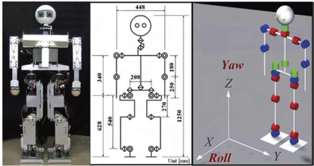
Appearance of humanoid robot Bonten-Maru II
To realize robots in the real world, a sensor-based navigation function is required because they cannot autonomously operate based on environment recognition alone. The numerous types of sensors used in navigation tasks so far can be categorized into two types: non-contact sensors such as vision and laser range sensors, and contact-based sensors such as force and tactile sensors.
The current state-of-the-art-survey of robot navigation shows that most reports are related to perception-guided navigation, dealing particularly with non-contact sensors such as visual-based navigation (Seara, J. F., Schmidt, G. 2004, Okada, K. et al., 2003) and applications of a laser range finder system (Thompson, S. et al., 2006). Indeed, most reports are related to applications involving non-legged robots such as mobile robots and humanoids on a static platform (Remazeilles, A., Chaumette, F. 2007, Ogata, T. et al., 2005). Our survey of journals and technical papers found very few works reporting navigation strategy for a biped humanoid robot (Gutmann, J. et al., 2005, Okada, K. et al., 2003). This current state of research probably reflects the complexity of the biped locomotion of a humanoid robot that involves trunk movement and stability issues.
In normal conditions, obviously a navigation system that applies non-contact sensors provides intensive information about the environment (Sagues, C., Guerrero, J. J. 1999). However, robots cannot just rely on such sensing information to effectively work and cooperate with humans. For instance, in real applications robots are likely to operate in areas where vision information is very limited, such as in a dark room or during a rescue mission at an earthquake site (Nasu, Y. et al., 2003, Diaz, J. F. et al., 2001). Moreover vision sensors have significant measurement accuracy problems resulting from such technical problems as low camera resolution and the dependence of stereo algorithms on specific image characteristics. Furthermore, the cameras are normally located at considerable distances from objects in the environments where the operation takes place, resulting in approximate information of the environment. In addition, a laser range finder has also been applied (Thompson, S. et al., 2006) that can produce precise distance information and provide more accurate measurements than vision sensors. However, embedding such sensors with their vision analysis systems in a walking robot is impractical due to size and weight.
A navigation system that applies contact-based sensors can solve the above problems, particularly for a biped walking robot system (Hanafiah, Y. et al., 2005). This type of sensor can accurately gauge the structure of the environment, thus making it suitable to support current navigation systems that utilize non-contact sensors. Furthermore, the system architecture is simpler and can easily be mounted on the walking robot body. However, to effectively navigate robot locomotion based on such sensing information, developing a reliable navigation strategy in the robot control system is necessary.
Related with navigation strategy in a robot system, several approaches such as a mapping strategy (Tu, K., Baltes, J. 2006), application of collision prediction functions (Kyriakopoulos, K. J., Saridis, D. J. 1993) and on-line learning strategy (Shah Hamzei, G. H. et al., 1999) are been used. However, in this research, we focus in real-time motion trajectory generation in biped walking robot based on contact interaction information of the robot's arms with objects. This method is simpler but effective to support visual-based navigation. We analyzed the robot's locomotion functions and proposed a contact interaction-based navigation strategy embedded in a multi-tasks algorithm.
Navigation Algorithm
In the proposed humanoid robot navigation strategy, we create a motion algorithm consisting of four important tasks: searching tasks, self-localization tasks by grasping, correction of locomotion direction tasks and obstacle avoidance tasks. The algorithm, whose flowchart is shown in Fig. 2, is comprised of the formulations of kinematics solutions, interpolations of manipulator's end-effectors, and the formulations of biped trajectory analysis. Moreover, formulations of force-position control are applied in the proposed algorithm to recognize contact events of the arm with objects.

Contact interaction-based navigation algorithm
The searching process to find objects is performed in sequence using both robots arms on which force sensors are mounted as end-effectors for force control. During the searching tasks, the motion will stop when the arm end-effector touches an object and the force detected exceeds the maximum force parameter value. At this point, each encoder at the arm joints records angle data and by solving direct kinematics calculation of the joint angles, the end-effector position will be obtained. Fig. 3 shows the searching and detection area of both arms. The detection range covers the robot's front, right, and left sides within the arms' reaching range.
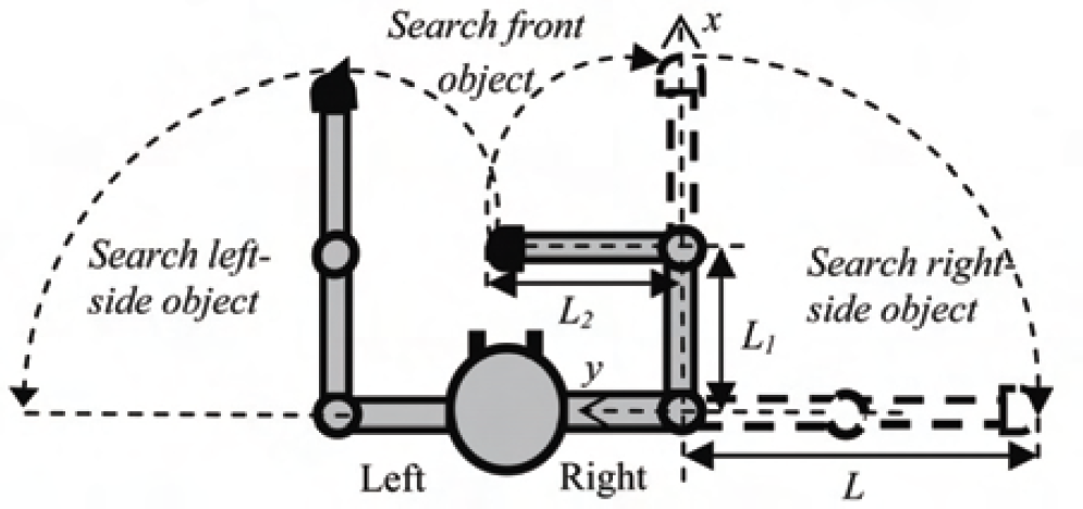
Structural dimensions, search and detection area of the robot's arm
At this current stage, object detection is limited to a solid object with a flat surface whose height is about the same as the robot. To effectively navigate robot locomotion and simultaneously simplify the navigation tasks, detection motion priority is given to the right arm to lead the searching process. Basically, the right arm searches for objects, grasps them to define self-localization, and confirms their presence. The left arm functions as an obstacle checker to navigate the robot, either to correcting its orientation or performing obstacle avoidance. During the searching process, when the object is only detected by the left arm, the robot will turn to its right side and repeat the search and detection process. By applying this method, intelligent detection of most objects around the robot can be demonstrated. In addition, the method provides reliable relationships between self-localization and obstacle avoidance tasks.
Before performing the navigation tasks, the robot must recognize its position and orientation within the environment in which it operates. This process is called self-localization. In our proposed navigation strategy, self-localization is performed by grasping an object's surface to define its orientation. Based on this information, the relative relations of distance and angle between the robot and the object can be defined.
During the grasping process, the position of the arm's end-effector is defined by performing kinematical calculations. Meanwhile the grasping movement of the end-effector on the object surface is controlled using force- position formulations based on force information obtained by the force sensor. In these formulations, we applied parameters of maximum force F
max
, minimum force F
min
, and the arm's end-effector's shifted distance in one sampling time l. This controls the contact pressure and the movement of the end-effector on object's surface. The force-position controls are explained as follows, and F is the force value detected by the force sensor:
For grasping an object at the front position:
For grasping an object at the right-side position:


Here, the reference position or the targeted point of the end-effector is described as P ref , and the current position is described as P cur . Based on detected force F, which is controlled by the above parameters, the end-effector's targeted position P ref in regard to the global axes x-y plane is defined from the end-effector's current position P cur in one sampling time.
Figure 4 shows the robot performing a grasping motion. The data of the arm's end-effector position were saved and compiled in the robot control system, as shown in the graph in Fig. 5. This figure also indicates the geometrical analysis of the robot position and angle after the grasping process. The position data are calculated with the least-square method to result for a linear equation, as shown in (7) where a is the slope of the line and b is the y-intercept. A straight line from the reference coordinates origin that is perpendicular with (7), which describes the shortest distance from robot to wall, is defined in (8).

Robot arm during grasping on object surface
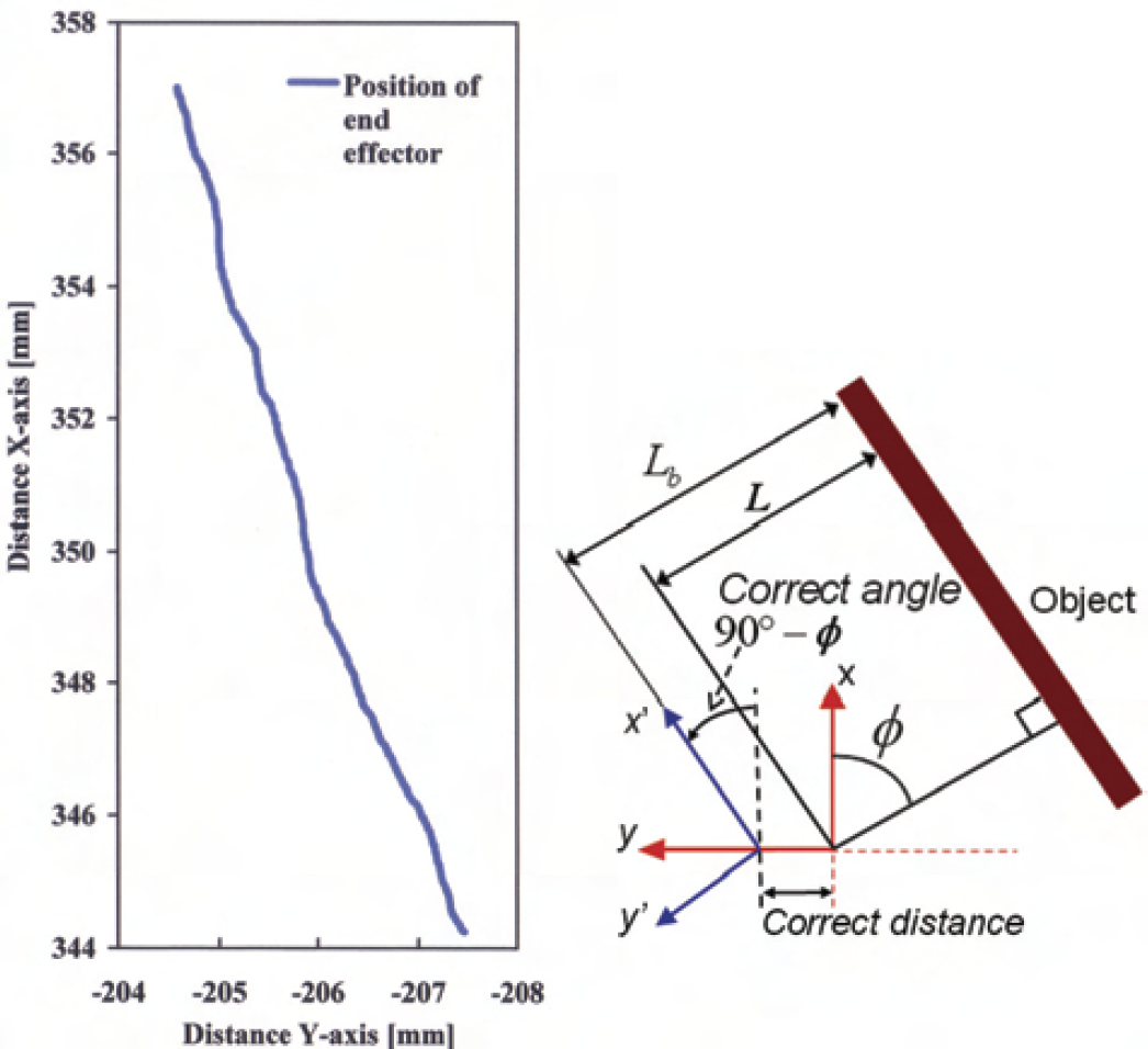
Results for grasping right-side object and geometrical analysis after grasping process
Consequently, the intersection coordinate at the x-y axes plane is defined in (9). Here, grasping angle φ is an angle from the x-axis of the robot reference coordinates to the perpendicular line of (8). Finally, the distance of the robot to object L and grasping angle φ are shown in (10) and (11), respectively.


The correction of locomotion direction consists of the correction of distance and angle, which refers to the values of L and φ. When grasping the front object, correction of the robot's distance was simply performed by walking in backwards. For safety, the quantity of steps is calculated referring to the value of distance L. When grasping the right-side object, correction of distance involves trajectory generation of legs to take side-steps away from the object. However, to prevent the probability of collision when the robot performs a correction angle, if the grasping angle φ is 0<φ≤45° the robot will walk one step backwards before taking a side-step. If the grasping angle φ is 45°<φ≤90°, the robot will immediately take a side-step away from the object. At this point, side-step length S is defined from (12). Here, L
b
is the safety distance between the robot and the object:

From (12), boundary conditions are fixed as (13) and (14). In these equations, α and β are minimum and maximum parameter values of the step length of the humanoid robot legs during a side-step.


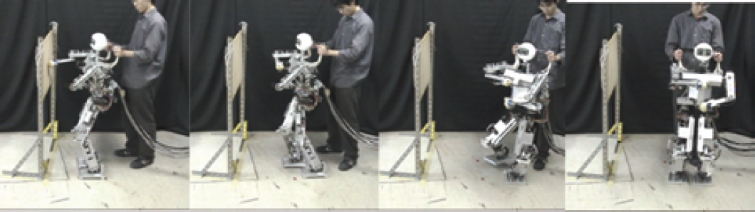
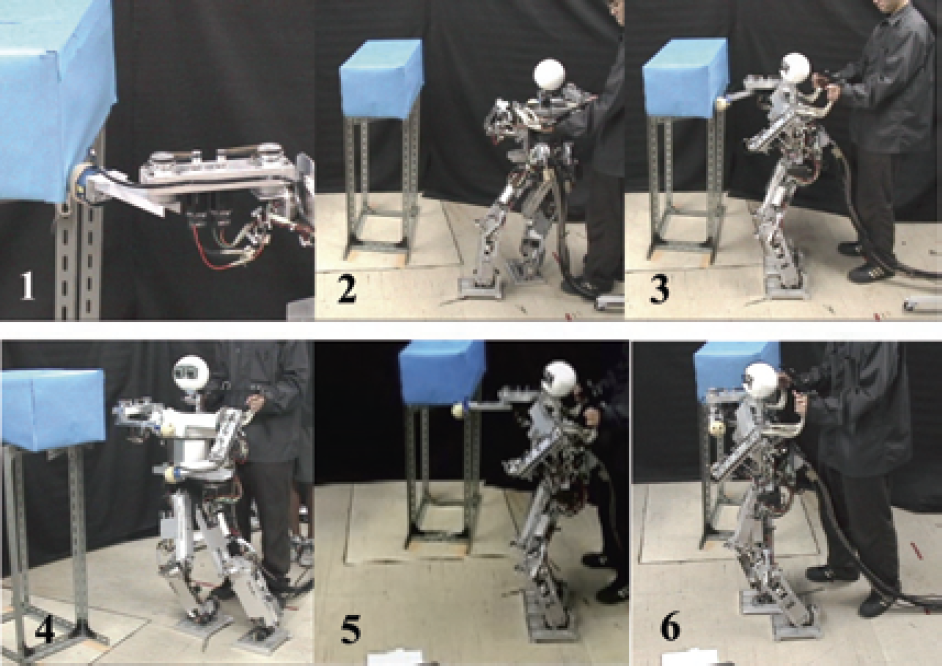
Correction of the robot's angle is performed by changing the robot's locomotion direction to 90°-φ (refer x' y'-axes in Fig. 5), so that the robot's final orientation is parallel with the object's surface orientation. This correction motion is generated by rotating the hip-joint yaw to the desired angle while controlling the swing leg's end-point position. Figures 6 and 7 show sequential photographs of the humanoid robot correcting position and angle after grasping the front and right-side objects, respectively.
Correction of humanoid robot's distance and angle after grasping front object

Correction of humanoid robot's distance and angle after grasping right-side object
Obstacle avoidance consists of three important tasks: checking the obstacle using the left arm, rotating the robot's orientation, and confirming the obstacle using the right arm. Basically, the tasks are performed after correcting the robot's distance and before proceeding to the correct angle. However, if no obstacle has been detected, the robot will continue to correct its angle. The left arm's range of motion while checking for obstacles is equals to the correction angle 90°−φ.
Figure 8 shows the obstacle avoidance tasks in the proposed navigation strategy. Once an obstacle has been detected, the robot will rotate its orientation to face the obstacle to confirm its position at a wider, more favorable angle, finally avoiding it. After the obstacle is detected and the robot orientation has changed to face the obstacle, whether the obstacle still exists within the locomotion area must be confirmed. This process is performed by the robot's right arm, which searches for any obstacle in front of the robot within its reach. If the obstacle is detected within the search area, the robot will walk in a side-step direction. The robot's arm will repeat the process of confirming the obstacle's presence until the obstacle is no longer detected. Once this happens, the robot will walk forward and complete the process of avoiding the obstacle.
Demonstration of obstacle avoidance tasks
Trajectory generation for articulated manipulators is basically defined by solving forward and inverse kinematics problems. The calculation to solve kinematics problems for robotic joints is complicated and time-consuming, especially when involving a complex joint structure. Furthermore, the computation of joint variables is also needed to detrmine the required joint torques for the actuators. To develop a sufficient theoretical strategy in humanoid navigation by generating efficient gait pattern trajectory, we performed kinematical analysis of joint trajectories for 3-dof arms and 6-dof legs to simplify the formulations to generate the trajectory of articulated humanoid's manipulators. This analysis is taking reference of the previously proposed kinematical solutions for Bonten-Maru II (Hanafiah, Y. et al., 2006).
Forward Kinematics Solutions
Forward kinematics solutions are used to define the robot arm's end-effector position in correlation with the force data obtained during touching and grasping tasks. Bonten-Maru II has three dofs on each arm: two dofs (pitch and roll) at the shoulder joint and one dof (roll) at the elbow joint. Figure 9 shows the arm structure and distribution of joints and links. Figure 10 displays a model of the robot's arm describing the distributions and orientation of all joint coordinates. Coordinate orientation follows the right-hand law, and a reference coordinate is fixed at the intersection point of two joints at the shoulder. To avoid confusion, only the x and z-axes appear in the figure. From the Denavit-Hartenberg convention (Denavit, J., Hartenberg, S. 1995), definitions of the homogeneous transform matrix of the link parameters can be described as follows:

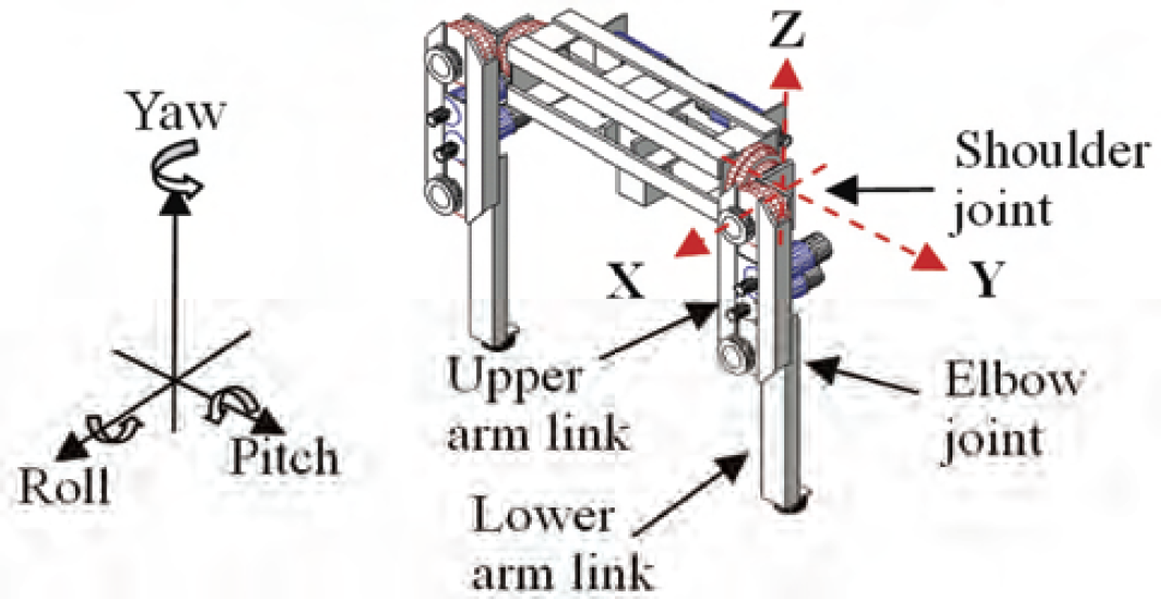
Bonten-Maru II's arm structure

Configurations of joint coordinates at 3-dofs of Bonten-Maru II's arm
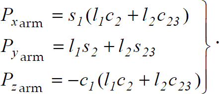
Consequently, Eq. (16) is solved to obtain the forward kinematics solution for the robot arm:

The end-effector's orientation with respect to the reference coordinate (
h
o
R) is shown in Eq. (17), while the position of the end-effector (
0
P
h
) is shown in Eq. (18). The position of the end-effector in regard to global axes P
x
, P
y
and P
z
can be defined by Eq. (19). Here, s
i
and c
i
are abbreviations of sinθ
i
and cosθ
i
respectively, where (i=1,2,…,n) and n is equal to the number of dofs.

As understood from Eqs. (17) and (18), a forward kinematics equation can be used to compute the Cartesian coordinates of the robot arm when the joint angles are known. These equations are used in the searching tasks of the robot's arm, as mentioned above.
In real-time applications it is more practical to provide the end-effector's position and orientation data to the robot's control system than to define each joint angle that involved in complicated calculations. Therefore, inverse kinematics solutions are more favorable for generating the trajectory of complex humanoid robot manipulators. In this section, we presents inverse kinematical analysis on a 6-dofs Bonten-Maru II's leg. Figure 11 shows the structure and configuration of joints and links in it, and Fig. 12 shows a model of it that indicates the configurations and orientation of each set of joint coordinates. Here, the link length for the thigh is l1 and l2 for the shin. The same convention applies for the arm link parameter mentioned earlier. Here, a coordinate transformation matrix in Eq. (20) is solved to define joint rotation angles at the leg.

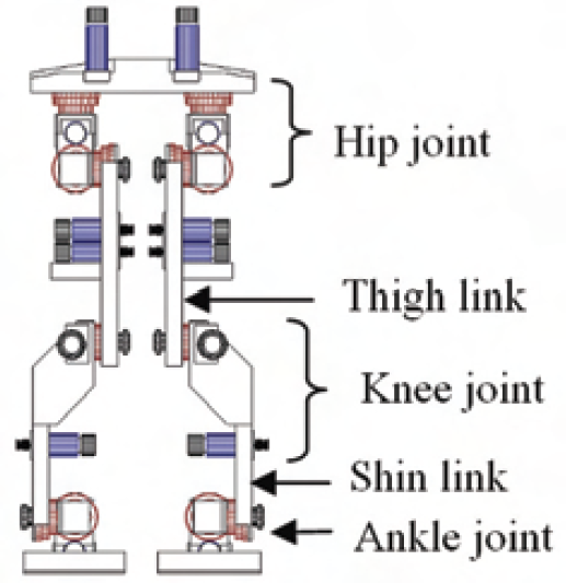
Bonten-Maru II's Leg structure

Configurations of joint coordinates of 6-dofs Bonten-Maru II's leg
Consequently, the formulations of joint rotation angles at each joint θ1leg~θ6leg are defined in the following Eqs. (21)~(26), where θ
i
= arctan2(y,x) at (−π ≤ θ
i
≤ π).


Eventually


A common way of moving a robot's manipulator from start point to end point in a smooth, controlled fashion is to have each joint move as specified by a smooth function of time t. Each joint starts and ends its motion at the same time, thus the robot's motion appears coordinated.
In this analysis, we employ degree-5 polynomial equations to solve interpolation from start point P0 to end point P
f
because it provided smoother interpolation compared to commonly used degree-3 polinomial equations. Velocity and acceleration at P
0
and P
f
are defined as zero; only the position factor is considered as coefficient for performing interpolation. The interpolation equation is defined in Eq. (31):

In walking locomotion, motion time is the time to perform one step that is normally fixed by the operator. To perform a smooth and reliable gait, it is necessary to define step-length and foot-height while transferring one leg in one step. The step-length is a parameter value that can be adjusted and fixed in the control system.
On the other hand, the foot-height is defined by applying ellipse formulation, as shown in the gait trajectory pattern in Fig. 13. For walking forward and backward, the foot height at z-axis is defined in Eq. (33). Meanwhile during side steps, the foot height is defined in Eq. (34):


Gait trajectory pattern
Here, h is the hip-joint height from the ground. In real-time operation, biped locomotion is performed by given the leg's end point position to the robot control system so that the joint angle at each joint can be calculated by inverse kinematics formulations. Consequently, the joint rotation speed and pattern is controlled by the formulation of interpolation. By applying these formulations, each gait motion is performed in smooth and controlled trajectory.
One of the most sophisticated forms of legged motion is biped gait locomotion. Since the biped walking pattern will greatly influence humanoid robot navigation, taking a brief look at the biped locomotion characteristics is worthwhile. Human locomotion stands out among other forms of biped locomotion chiefly in terms of the dynamic systems point of view. During a significant part of the human walking motion, the moving body is not in static equilibrium. In contrast, for a biped robot two different situations arise in sequence during walking: the statically stable double-support phase in which the whole structure of the robot is simultaneously supported on both feet, and the statically unstable single-support phase when only one foot is in contact with the ground while the other foot is being transferred from back to front.
It is understood that to realize a stable gait motion, Center of Mass (CoM) and Ground Projection of Center of Mass (GCoM) must be in a straight line where the GCoM must always be within the foot sole area, as shown in Fig. 14. If GCoM is outside of the foot sole area, the robot will lose its balance and fall down. Notice that when swinging one leg, the waist moves on top of another leg to shift its CoM position so that the CoM is centered with the GCoM. These movements simultaneously bring together the whole robot trunk to the left and right. To safely navigate the biped robot locomotion, the trunk movement of the robot body must be considered. In this study, trunk movement is considered to be parameter value r, which is the distance from the waist-joint to the hip-joint.

Static walking model for biped robot
A simulation using animation that applies GNUPLOT was performed to analyze and confirm of the robot joint's trajectory generation. Figure 15 presents an animation screen of the robot's trajectory, which features a robot control process, a motion instructor process, and robot animation. At this time grasping angle φ was fixed to be 20° so that the correction angle became 70°.
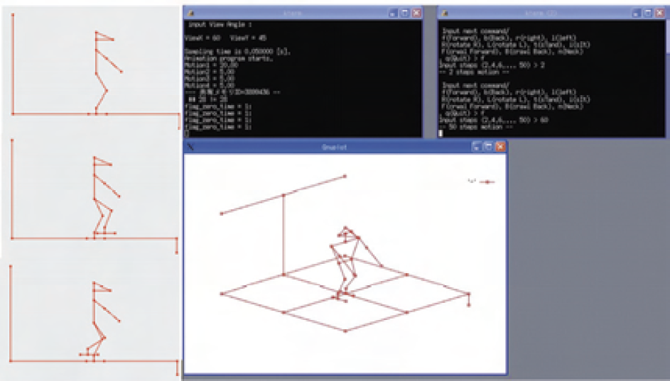
Simulation interface of humanoid robot trajectory
Each joint's rotation angles were saved and analyzed in a graph structure. For example, graphs for the left and right legs are plotted in Figs. 16 and Fig. 17 during yawing motion to change the robot's orientation to face the detected obstacle in obstacle avoidance tasks. The graphs show the smooth trajectory of the rotation angles at each leg's joint. Notice that the hip-joint yaw at the left leg is rotating within 70° to correct the robot's orientation. These simulation results verified reliability of the proposed formulations in trajectory generation.

Rotation angle of the left leg joints while turning to left in the obstacle avoidance tasks

Rotation angle of the right leg joints while turning to left in the obstacle avoidance tasks
The observation of human behavior during operation in a dark room shows that at first the human subject gropes to identify the nearest object to recognize his position in the room. Inspired by this scenario, the humanoid robot starts its navigation process by searching for the nearest object to define self-localization so that it can recognize its position and orientation in the environment where the operation takes place. Furthermore, to obtain optimal motion, priority is given to right-side direction to guide the robot locomotion in conjunction with a strategy to avoid obstacles. The robot continuously generates suitable locomotion based on the contact information, according to the proposed algorithm explained in the previous section. Next, the navigation of a walking robot requires accurate collision avoidance parameters to ensure the robot's safety when performing locomotion in the navigation tasks. The robot trunk movement parameter r and the arm detection area, which equals the length of arm L t must be considered. The robot travel distance (step length and quantity) in walking motions is controlled based on these parameter values. For forward and backward walking motions, travel distance must be less than the value of L t . For the side-stepping motion and tangential walking during the correction process, the travel distance is fixed to be less than the parameter value of L t + r.
Experiment and Result
Experiment Condition
An experiment was conducted to evaluate the proposed navigation strategy using Bonten-Maru II in a room where walls and obstacles were arranged as shown in Fig. 18. The proposed navigation algorithm was installed in the robot control system as shown in Fig. 19. Since the robot's vision sensors were not connected to the system, therefore the robot locomotion had to rely on the contact interaction of the arms equipped with force sensors.

Layout of humanoid robot locomotion in contact interaction-based navigation experiment

Control system architecture of Bonten-Maru II
A human operator acted as the motion instructor and controlled the robot motions by sending instructions to the robot control system, and received feedback of contact information from the robot controller module. The operator had prior knowledge of the room arrangement but did not know the robot's exact starting position. During the experiment, contact information was fedback to the motion instructor so that he could decide subsequent instructions.
In this research, we utilized a 1.25-m tall, 32.5-kg research prototype humanoid robot called Bonten-Maru II (Fig. 1) who was designed to mimic human characteristics as closely as possible. The robot has a total of 21 dofs: six for each leg, three for each arm, one for the waist, and two for the head. Each joint is driven by a DC servomotor with a rotary encoder and a harmonic drive-reduction system and is controlled by a PC with a Linux OS. The motor driver, PC, and power supply are placed outside the robot. The robot's control system consists of three modules: a motion instructor, a robot controller, and shared memory. The robot systems can operate in a simulation and real-time modes.
Bonten-Maru II is equipped with a six-axis force sensor (IFS-67M25A50-I40, Nitta Corp.) in both arms. The advantages of this force sensor include its highly accurate force detection and its capability to detect very high force in wide range; thus it is suitable for force-position control in articulated robotic manipulators and robust enough to be avoid damage while touching and grasping objects. Four pressure sensors under each foot provide a good indication that both legs are contact with the ground.
Results and Discussion
Figure 20 shows sequential photographs of actual robot locomotion during the experiment. First the robot sought the nearest object using both arms. When the object was detected, the robot grasped its surface to define self-localization and then corrected its locomotion direction after checking for obstacles in the correction area. The robot continued its locomotion while touching and avoiding objects in its path. When necessary, the robot changed its direction by turning right or left. Finally, the robot managed to complete the navigation tasks safely and reached the target end point.

Sequential photographs of humanoid robot locomotion in contact interaction-based navigation experiment
The proposed strategy embedded in the robot control system combined with contact interaction data provided by the force sensor guided the human operator to recognize the room condition and make correct decisions to guide robot locomotion. Furthermore according to the proposed method, sequential motions of the right and left arms were effectively operated, whereby priority was given to the right arm. These enabled the robot to successfully check for and confirm the presence of objects and obstacles, consequently assisting it to perform the necessary trajectories in each task. Application of this method exhibited good performance and demonstrated a reliable relationship between each task in the proposed navigation strategy.
We presented the development of a contact interaction-based navigation strategy for a biped humanoid robot in which the arms are equipped with force sensors. We proposed a motion algorithm consisting of searching tasks, self-localization, correction of locomotion direction and obstacle avoidance. Priority was given to right-side direction to navigate robot locomotion in conjunction with strategies to avoid obstacles. In conjunction with the proposed algorithm, we defined a simplified approach for solving forward and inverse kinematics problems to generate efficient trajectory for the robot manipulators. In addition, analysis of gait trajectory patterns for the robot leg and consideration of biped walking charecteristics were performed to define efficient biped locomotion strategy. The proposed navigation strategy was evaluated in an experiment with a prototype humanoid robot operating in a room with walls and obstacles. The experimental results revealed good performance of robot locomotion in recognizing the environmental conditions and generating suitable locomotion to walk safely toward the target point. Finally, the proposed strategy demonstrated good potential to support current visual-based navigation systems. The proposed idea should contribute to better understanding of interactions between a robot and its surroundings. It is anticipated that using the proposed strategy will help advance the development of a reliable navigation system for humanoid robots so that they can further ‘adapt’ to environments that have been previously reserved for humans. Future work will focus in navigation tasks combining the proposed contact interaction-based navigation strategy with vision sensors.
Footnotes
8.
Part of this work was supported by fiscal 2006 grants from the Japan Ministry of Education, Culture, Sports, Science and Technology (Grant-in-Aid for Scientific Research in Exploratory Research, No. 18656079).