
Abstract
Multiped robots have become the focus of heated discussion lately, especially in applications involving rescue or military missions and underwater or extra-terrestrial explorations. The surroundings concerned are harsh and hazardous terrains, and predictably the malfunction rate is high. What if a leg is irreparably damaged? The original gait can no longer be used and an alternative gait must be taken for the robot to continue its mission. This paper studies and enumerates preferred alternative gaits for six- and eight-legged robots under a proposed severed leg scheme. A leg is assumed to be completely detachable when a failure occurs. Based on a new criterion called the progressive efficiency (PE), defined via the enhanced gait charts, along with other criteria like the stride length and the longitudinal stability, alternative gaits are evaluated. The tables of recommended gaits in this paper are useful for robots when a leg failure is foreseen. These tables not only provide a guideline as to what alternative gait to use, they also give insight into how important a certain leg is. A comparison between the severed leg scheme and the existing locked-joint strategy is also included.
1. Introduction
Recently, researchers have shown an increased interest in multi-legged robots. From space exploration, catastrophe response to mine-sweeping, there are many applications for robots in situations where people would be endangered or cannot go. Thus, robots may need to be used instead of humans in those kinds of mission. Legged robots have a wide range of applications and are used for many tasks that cannot be accomplished by wheeled ones.
There are several kinds of damage that can happen in a multiped robot, but in this paper we considered only the failure which is associated with legs as a broken leg can reduce the stability and efficiency of the robot.
A considerable amount of literature has been published on robot leg failure strategies and several attempts have been made to solve the problem of robot leg failure. In 1997, Inagaki [1] investigated leg failure situations in hexapod robots of which one leg had been damaged. He investigated five-legged walking gaits and found that by allowing a five-legged gait with chassis rearrangement, greater efficiency and adequate stability ranges could be maintained.
In 1998, Yang & Kim used the term “fault-tolerant” to refer to their alternative gait approach for hexapod robots in which two legs were lifted in every step [2]. Since the centre of gravity of the robot was always positioned at the intersection of the diagonals of the support polygon, stability was maintained even if one standing leg malfunctioned. After that, a five-legged gait could be used.
More recently, Yang proposed a scheme for retaining the fault-tolerant gait property of hexapod robots with certain leg failure [3], [4]. Each joint in this robot's leg system was assumed to be able to lock individually. Yang suggested that it was advantageous to lock the joint associated with a damaged motor. Thus, the locked joint leg could be used for support rather than to move and the gait sequence of the robot had to be rearranged accordingly.
In 2004, NASA developed an eight-legged robot for planetary exploration [5]. When one or two legs of this robot stopped to function, it could still maintain stability by switching to an alternative gait. But with the failure of three or four legs the stability declined radically and even a critical stability situation occurred. So NASA proposed crawling and gliding gaits to solve the problem.
From the above discussion, and also mentioned by English and Maciejewski [6], [7] and by Yi et al. [8], the solution for such damage can be divided into two categories. One is the aforementioned “locked-joint” scheme, which supposes that the resistance of the bad joint is so high that it is literally locked in a certain position, or that the joint is designed in a way that it can be fixed when failure is detected. On the contrary, the “free-swinging” scheme, which assumes that the broken motor or joint loses most of its resistance to external load, regards the damaged leg as a free-rotating dangling limb. In addition, in 2008, according to the commanded velocity, Mustafa and Kemal [9] studied and improved the problem of free gait generation and adaptability with reinforcement learning in normal conditions with no external effects causing unstability and in abnormal cases of deficiency in one of the rear-legs for a six-legged robot.
A new strategy, however, is proposed and discussed in this paper, which we name the “severed leg” scheme. This approach is designed to be a patent bio-mimicry of some legged animals that exercise autotomy (or loose legs involuntarily) in harsh situations [10], [11]. As opposed to the “locked-joint” or “free-swinging” schemes, a fully severed malfunctioned leg is far less likely to produce hindrance or unwanted side effects to other legs and the robot system. The cost of discarding a limb is great, but considering the seriousness of the mission to accomplish, most of the time this sacrifice is well justified.
This paper aims mainly to provide a reference for a multiped robot to retain mobility while it encounters disability in the legs. Under such unfavourable conditions, as its faculty is reduced, it is no longer pertinent to compute the dynamic stability of the robot. Thus, only static stability is discussed in this paper. Moreover, the mass of the legs is also deemed to be negligible, [12] [13] as in most insects and spiders.
2. The multiped robot model
Before delving into details, an explanation of the legged robot model is appropriate. The hexapod model used in this paper is shown in Fig. 1. Models with different numbers of legs, e.g., octopod robots, can also be created similarly. As in Fig. 1, a three-dimensional coordinate system is used in which the origin is placed at the CG of the robot. The Y-axis denotes the direction of motion. The XY plane is parallel to the terrain and the robot is symmetrical with respect to both YZ and XZ planes. Legs are numbered as L1, L2, L3 and R1, R2, R3, with L1 and R1 being the leading pair of legs. We require that all leg modules are equipped with some severing means, as described in [14], so that any leg can be discarded when needed. Each leg has three degrees-of-freedom and can swing backward (as in a propulsive stroke) and forward (as in a return stroke) with the same velocity. When the robot moves onward, the path of the tip of a leg, when projected onto the XY plane, is a straight line parallel to the direction of motion. In this paper, we let the maximum stride length of each leg be 2S, meaning a leg can move ±S from its neutral position, which is depicted in Fig. 1.

A common hexapod robot model used in this study.
3. Alternative tripod gaits
Most insects can walk with a tripod gait, which is a fast and statically balanced gait (SBG) for hexapods. However, when one or more legs are missing, a regular tripod gait is no longer possible. Now, let's consider losing one leg. For our symmetrical hexapod model, there are only two distinct cases: losing leg R2 or R3. The R2 case is shown in Fig. 2, labelled as 6–1–R2, which means the hexapod robot with one leg missing and the missing leg is R2. Note that we only discuss morphologically distinct cases in this paper. If an SBG is still desired, as in most multiped robot designs, two tripod groups of legs are required, but there are only five legs. To get around this, a “common leg” must be shared in both tripod groups. We will see that for amputated robots, the assignment of the common leg is crucial in finding sustainable alternative gaits with better stability. As stated before, when we say stability, we mean static stability of the robot. This implies that the CG of the body must be located within the support polygon at all times to prevent the robot from toppling. On the contrary, dynamic stability requires that the zero moment point, taking into account the moments produced by the reaction and the inertia forces, must also be within the support polygon of the robot [15], [16].

The 6–1–R2 case, as illustrated by robot schematics (a) and by the enhanced gait chart (EGC) of the robot (b). In each interval the robot travels a distance S.
The purpose of this paper is to compare alternative gaits of multiped robots with severed legs. A key criterion of comparison is the gait stability, more precisely, the longitudinal stability margin sL as proposed by McGhee and Frank [17] and Song and Waldron [18], [19]. A plot of the movement of the legs and the robot body, as shown in Fig. 2(a), is used for measurement of gait properties. A gait cycle is composed of a series of recurring walking steps, e.g., [A-B-C], as denoted by circled capital letters A, B and C in the figure. The support polygon for each walking step is shown in dashed lines connecting all standing legs. For SBG, the centre of gravity c of the robot can never fall outside the supporting polygon. Comparing the support triangles of steps A and C in Fig. 2(a), we see that leg R3 is the common leg.
Possible displacement ranges of the legs are shown by vertical lines in the figure. In each walking step, if a leg moves, it moves from the grey dot to the white dot in our schematics. In step A, legs are originally placed at their neutral positions. When supporting legs move, they swing backward and their collective effort contributes to the forward motion of the body, as indicated by the white arrows in steps A and C. The swinging supporting legs are propulsive legs, and in propulsive steps, the supporting polygon appears to move backward. This is because the reference frame is fixed on the robot.
If the supporting legs do not have any motion in a step, as in B, they are called stationary legs, and this is a stationary step. In such a step, the robot remains in its previous position and waits for a leg (normally the common leg) to adjust its position. A gait with stationary steps is not continuous. The non-supporting legs in either propulsive or stationary steps will make a forward swinging movement. They are referred to as swinging legs. Ideally, either a swinging or a propulsive leg should swing to the extreme positions of its range in every step in order to achieve maximal speed, as in the regular tripod gait.
However, this is not always possible for robots with severed legs. Take step C in Fig. 2(a) for example. The propulsive legs L1, L3, and R3 can move only half the maximum stride length, since after that the CG will not be inside the supporting triangle. In step A of Fig. 2(a), similarly, the robot can move only half of the maximum stride length. This is because in continuous motion, step A occurs immediately after step C and the common leg R3 has just travelled from its foremost position to the middle. Therefore, the stride length of R3 in step A is decreased. This is an unavoidable limitation of using a common leg.
4. Progressive efficiency
A gait cycle usually includes the non-stationary steps (centre of gravity with a forward motion) and stationary steps (centre of gravity with a non-moving motion). Such as step E in Fig. 3 which includes the “stetting stroke”. Too many stetting strokes will reduce the progressive efficiency. In this study, progressive efficiency (PE) is defined as PE= b / a, where the denominator “a” is the time of the entire gait cycle and numerator “b” is the time used in non-stationary steps.
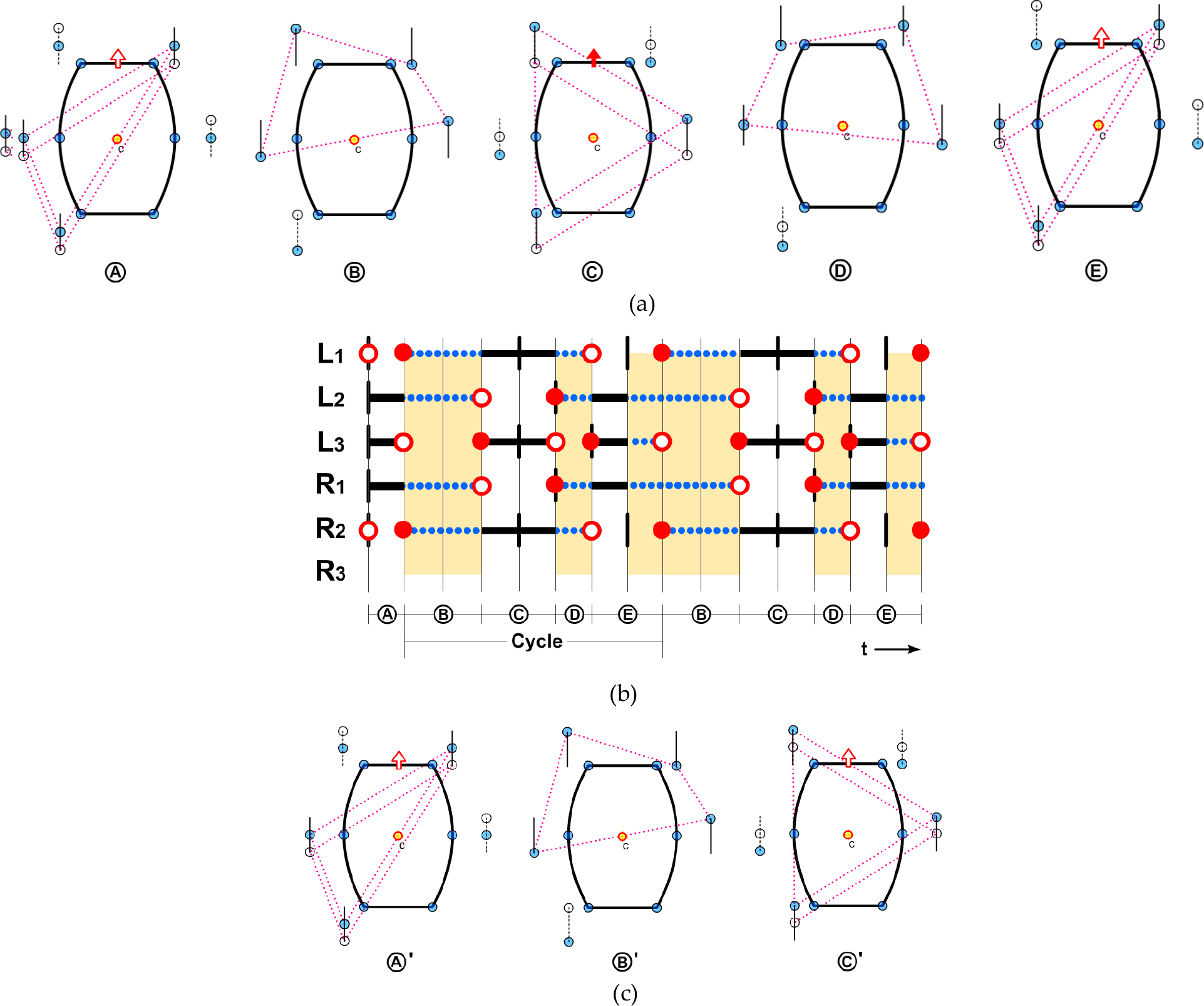
The two possible 6–1–R3 cases, as shown by robot schematics (a) and (c), and EGC (b). In each interval the robot also travels S.
From the above discussion, there are two unwanted consequences of losing a leg. One is reduction of stride length and the other is the introduction of stationary steps. Since in a stationary step the robot simply halts, and the longer this step, the poorer the walking efficiency, in order to quantify this loss of gait efficiency, we observed the robot motion from Fig. 2(b), an enhanced gait chart (EGC). The robot schematics in Fig. 2(a) are used to show the supporting polygon and its relation with the CG of the robot. The EGC shows, with respect to the time, whether or not the leg is placed on the ground.
The construction of EGC is quite similar to a traditional gait chart, which was initially named “gait diagrams” by Hildebrand [18], [19], as he used it to record the gaits from motion pictures. In an EGC, a hollow circle indicates the moment when a leg begins to leave the ground and a solid circle shows the instant when a leg touches the ground. A gait cycle is evenly divided into a number of intervals, as in Fig. 2(b), each interval representing the time for a leg to swing, either forward or backward, a distance of S, as in Fig. 1. Each grid in the horizontal axis represents the time for an S. Comparing Figs. 2(a) and 2(b), we see that the duration of step A and C is one interval long, whereas step B occupies two intervals. The short vertical bars mean neutral positions of the legs except R2. The thick solid horizontal lines are the propulsive stroke. Blank gaps between hollow and solid circles are then the return stroke. In this paper, a leg always takes the same time in forward and in backward motions within a gait cycle.
What are noteworthy in an EGC are the thick dot lines that represent the stationary legs. Intervals containing stationary legs are shaded and in such stationary steps there are no thick horizontal lines, in addition, the common leg is usually the only leg that moves. By counting the shaded intervals within a gait cycle, we define the PE of an alternative gait for multiped robots with severed legs. PE is the ratio of the time used in non-stationary steps to the time of the entire gait cycle. For an undamaged hexapod using the regular tripod gait, since there is no need for stationary steps, its PE is 100%. However, for the 6–1–R2 severed leg case, from Fig. 2(b) we see that PE is reduced to 50%. Half of the time is wasted in awaiting the common leg to return.
5. Hexapods with severed legs
There is another case for our symmetrical hexapod model to lose one leg: 6–1–R3. As illustrated in Fig. 3, the robot starts from its neutral position. If we choose L3 as the common leg, a possible gait arrangement can be planned as A-[B-C-D-E], with [B-C-D-E] being the recurring gait cycle. Step A in Fig. 3(a) is non-recurring since sometimes the robot needs a few preparatory steps before entering the recurrent gait cycle. Step C uses the full maximum stride length whereas steps A and E are limited to only half of that stride length. Note that step E, as seen from Fig. 3(b), actually consists of a propulsive and a stationary interval and the supporting polygons of the two are the same. Two stationary steps (B and D) are needed, in which the common leg L3 makes a full return in step B and a half return in step D. There are seven intervals constituting the recurring cycle of this gait, where four of them are stationary, marked as shaded regions in Fig. 3(b). Thus, the PE of this gait is 3/7=43%.
From this example, we realize that for the alternative gait of an amputated robot, the walking velocity is not directly proportional to the step length used. As in Figs. 2(a) and 2(b), the possibility of using the maximum stride length only costs us two extra stationary steps. That is, more adjustments and less travelling speed for the robot. The rule of thumb for planning an alternative gait, then, is to minimize the duration of stationary steps. In view of this, the gait for the 6–1–R3 case is redesigned as in Fig. 3(c). Although the stride length now for the propulsive steps (A' and C') is only half the maximum stride length, the PE of this gait is increased to 50%, the same as that of the 6–1–R2 case. From this example we also know that for a severed leg robot there could be more than one possible alternative gait. The gait with the largest PE will be labelled in this paper as the recommended gait to use.
For the case of losing two legs simultaneously, the best chances for a hexapod robot legs can be grouped into pairs in which a line joining a pair passes the CG. This is for cases 6–2–L2R2 and 6–2–L1R3, where instead of a tripod gait a slow wave gait can be used, as depicted in Fig. 4 by its EGC. Since much time is used in waiting for a leg to return, its PE is only 33%. However, to improve the PE, we can use a quick-return mechanism for the legs [20].
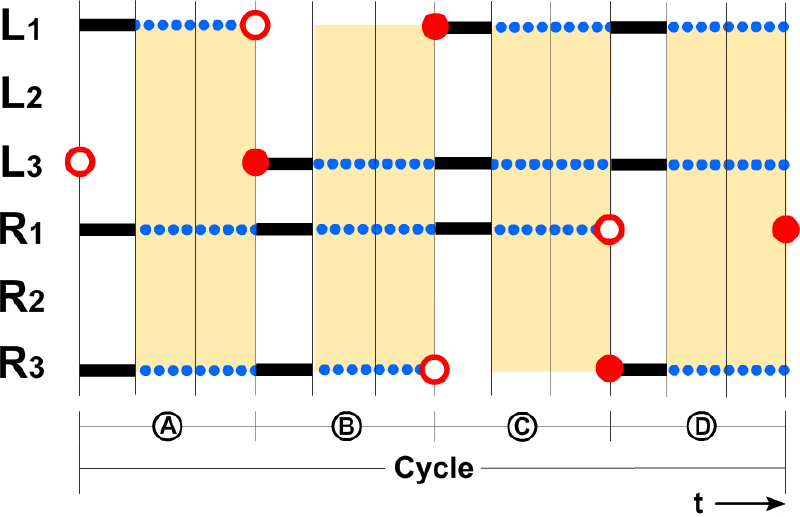
The enhanced gait chart of case 6–2–L2R2. Now the robot travels in each interval a distance of 2/3 S.
Other than the above cases, it is very difficult to walk for hexapod robot when two legs are missing. For cases like 6–2–L3R3, the robot can walk only if the CG of the robot can be relocated to the centre of the remaining legs. However, this is a complicated task for most machines. For cases like 6–2–L1R2, feasible tripod groups can be constructed, for example, with legs L2, R1, R3 and legs L3, R1, R3. However, such cases require complex gait planning and their PE will be reduced substantially [14]. Thus, it is not recommended to use such complex gait planning.
6. Comparison with locked-joint model
The possible distinct cases for the symmetrical hexapod robot with severed legs are shown in Table 1. Except rows with black “No RG” labels, each case has a recommended gait (RG) with optimum PE. The 6–0 row denotes the undamaged hexapod, assuming the regular tripod gait for which PE is 100%. When PE drops below 20%, it is virtually meaningless to use that gait. It is obvious that no statically balancing gaits (SBG) are possible for the 6–3 category and above.
Recommended gaits for hexapods with severed legs.

When there are many damaged legs, it is evident that their absence greatly hinders the mobility of the robot. Now let us consider the case where a damaged leg can still be used as a support, as assumed by the “locked-joint” scheme in [3], [4]. Note that such a leg can suffer only minor malfunction, since it has to retain the ability of raising and lowering its footpad from and to the ground. When only one leg is damaged and locked, as in the case of 6–1–R2, illustrated in Fig. 5(a), the original tripod gait can still be used. However, legs associated with the tripod containing the damaged leg R2, i.e., L1 and L3, do not have propulsive or return strokes. In Fig. 5, fine dashed lines indicate the steps when such legs are held stationary in the air. Thus, the PE of the 6–1–R2 “locked-joint” case is 2/4=50%, identical to that of the “severed leg” model. The same result applies to the case 6–1–R3.
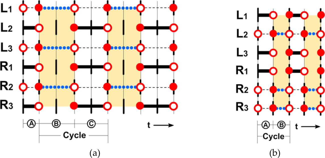
Two locked joint gaits 6–1–R2 and 6–2–L2R2 for hexapods. Each interval is S.
In case two legs are damaged and they belong to the same tripod group, then such a hexapod under “locked joint” assumption still has a PE value of 50%. However, if the damaged legs are not within an original tripod group, as in case 6–2–L2R2, an alternative tripod gait must be devised as follows. Let the damaged legs and one of the other legs form a tripod group. For example, we choose L2, R2, and R3 as a tripod, as in Fig. 5(b), and the other legs can form another tripod. Due to the unsymmetrical shapes of the support polygons [14], stride length is reduced to S, half of the maximum stride length. According to the EGC in Fig. 5(b), the PE of this alternative gait is 1/2=50%, still greater than that of the “severed leg” counterpart.
From the above analysis, we see that the two leg damage and one leg damage schemes for the hexapod robots have similar progressive efficiency. When two legs go bad, the “locked joint” model, with its pleasant assumptions that the legs can still be used as supports, is clearly better than the “severed leg” model. But when considering three malfunctioned legs, the “locked joint” model still has a chance of retaining motion, whereas a hexapod with three severed legs is totally disabled. However, the “locked joint” model is very optimistic and it does not guarantee applicability to all realistic situations.
7. Octopods with severed legs
Using the methodology presented above, in this paper we compared alternative gaits for a symmetrical octopod with severed legs. The recommended gaits corresponding to cases where one or two legs are missing are shown in Table 2. Since an octopod enjoys the luxury of two more legs than a hexapod, losing up to two legs seems to cause no decline in the PE, and in some cases the robot can even still use its original, undamaged gait. However, using an alternative gait plan is recommended as shown in Table 2.
Recommended gaits for octopods with one or two severed legs.

In each row of Table 2, the modified support polygons are listed. It is noted that a PE value of 100% means that there are no stationary steps in the walking cycle and the gait is absolutely continuous. Since the PE remains the same, we choose the support polygons that maximize the longitudinal stability sL of the robot. Governed by the shapes of the modified support polygons, in some cases the step lengths of the octopod may have to reduce to S. In the last rows of the table, some gaits with irregular supporting polygons are not recommended, since their pattern is not easy to program into a robot's memory.
It is also interesting to note that while Table 2 is originally designed to show recommended alternative gaits for an octopod robot with missing legs, it can also be used to indicate the importance of each individual leg in a specific situation. Greater care must be taken to protect the more important leg. For instance, say we have already lost L2, this is not a significant problem for an octopod since we can still have full PE and maximum stride length. What if we lose another leg? In Table 2 we see that losing R3, L3, R2 or L4 on top of L2 produces very different results. We do not want to lose R2 or L4, since we will have unusable, not recommended gaits. Losing L3 reduces the stride length, while losing R3 has no effect at all. With this observation, we know that when L2 is gone, protecting R2 and L4 has a much higher priority than protecting L3 or R3.
Results for an octopod losing three legs are listed separately in Table 3. Now the selection of a common leg (denoted as CL in the table) is necessitated. Again, only common legs that lead to the greatest PE and most stable support polygons are shown. Gaits with insufficient PE are labelled as not recommended (No RG). In general, for 8–3 octopod cases, PE is no better than 50%. In two extreme cases, the robot cannot move at all. As for the stride length, only two cases retain the maximum value of 2S.
Recommended gaits for octopods with three severed legs.
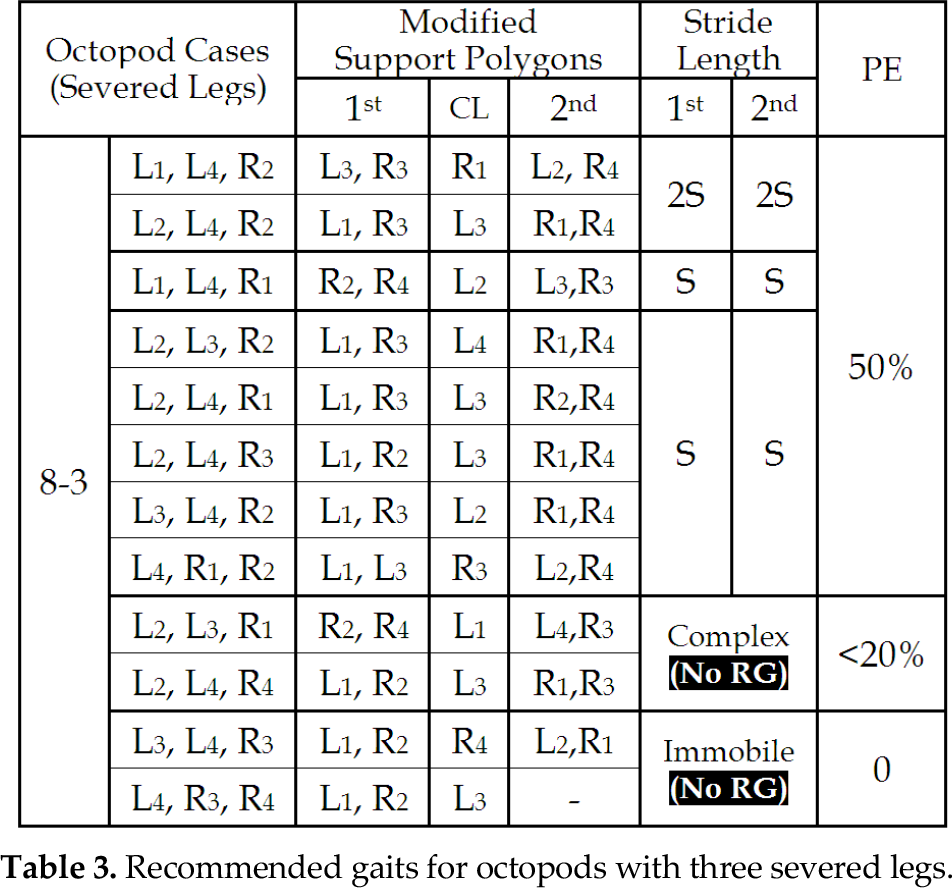
As the robot continues to lose more legs, the maximum PE for 8–3 cases reduces to 33%, and four of the 8–4 cases are immobile. Such gaits are deemed as of little practical value. Some of these more pathetically disabled octopod cases can be found in [14].
8. Conclusions
In this paper we propose a severed leg scheme for walking robots with leg malfunctions. In our assumption, on detecting an irreparable failure, the entire leg module is to be discarded. Following that, a comprehensive survey of usable alternative gaits for hexapod and octopod robots with one or more severed legs is presented. We also include a comparison between the severed leg strategy and the older locked-joint scheme. For gait comparisons, the first criterion we use is the PE, which is defined as the progressive efficiency and is related to the amount of stationary time in a walking cycle. The stalling of the robot happens when it is waiting for a common leg to return. We also use conventional criteria, e.g., the stride length and the longitudinal stability (sL).
Most severed leg multiped robots can no longer use their original, undamaged, gait sequence, however, by redefining the supporting polygons and consequently rearranging the gait sequences, in many cases the robot can still walk with some acceptable stability and, for some octopods, even unaltered efficiency. Epitomized in the tables are the recommended gaits for various severed leg situations in hexapod and octopod machines. The tables also show how important a leg really is. It is therefore advisable for a robot designer to have these preferred gaits programmed into the robot's memory. Should an adverse condition happen to the robot, it will know which alternative gait pattern it should turn to.
Footnotes
9. Acknowledgments
The authors are much indebted to the National Science Council of Taiwan for supporting this study under research grant NSC 95–2221-E-110-035-MY3.