
Abstract
In modern day, from planetary exploration, disaster response to antiterrorism mission multiped robot has become the major tool. Smart robot with effective gait plan may play a significant role in such missions. But if a leg is injured, it is not possible to repair in this kind of mission. Then robot needs some alternative strategies to complete its mission. This paper proposes a removable sliding leg approach to solve this problem. A fault leg can be detaches and other legs can be slide to better position by the command of operator to get optimum alternative gait configuration. Based on leg sequence, stride length, longitudinal stability and efficiency, alternative gaits are evaluated. This paper recommends tables for different gait sequence with progressive efficiency. These tables can provide options for alternative gait and information about certain damaged leg. Moreover, a procedure for a multi-legged robot to complete its mission after serious leg failure is included. By taking the recommended tables and procedure, the multiped Robot can overcome any fault event and maintain stability and efficiency.
Introduction
From space exploration, catastrophe response to mine-sweeping, there are many applications for robot in situation where people would be endangered or cannot go. The surroundings concerned are harsh and hazardous terrains, and the malfunction rate is high. Thus, it may need to use robots instead of human for that kind of mission (Saitta et al., 2009; Wang et al., 2010; Ahmed et al., 2010). Legged robots have a wide range of applications and are used for many tasks that cannot be accomplished by wheeled ones. (Habib M. K. 2007; Mori et al., 2005; Rizo et al., 2003; Baudoin et al., 1999). In this study, we explored the legged robot, commonly seen humanoid two-legged Robot (Biped Robot), four-legged Robot (Quadruped Robot), six-legged imitation insect Robots (Hexapod Robot), and spider eight-legged Robot (Octopod Robot). Although the walking strategy is obviously affected by the number of legs, but there is much similarity in the gaits of robots with multi legged. This study focuses on six-leg robots with extensions to higher number of legs.
A considerable amount of literature has been published on Robot leg failure strategies. Inagaki (1997) investigated the leg failure situations in hexapod robots of which one leg was damaged. He suggested some leg and chassis rearrangement to meet the requirements of work coefficient and also proposed each leg with large work space. In other words, Robot should have long legs and work space with interfere each other. However, this rearrangement also changed the body configuration of the robot. Moreover, for some application it is not possible to have long leg with large work space. Yang & Kim (1998) recommended “fault-tolerant” gait approach for hexapod robots, in which two legs were lifted in every step. Since the center of gravity of the robot was always positioned at the intersection of the diagonals of the support polygon, stability was maintained even if one standing leg malformed. After that, five legged gait can be used. More recently, Yang (2005b) mentioned that it is helpful to lock the joint associated with a damaged motor. Thus, the locked joint leg could be used for support rather than to move, and the gait sequence of the robot had to be re-arranged accordingly. However, locking mechanism always cannot provide support. When collapse occurs at 2nd or 3rd joint in a leg, then it is highly possible that leg can no longer maintain stability. In 2004, NASA developed an eight-legged Robot for planetary exploration (Spenneberg et al., 2004). When one or two legs of this robot stop to function, it could still maintain stability by switching to an alternative gait. But in failure of three or four legs, the stability declined significantly, and even the critical stability occurred. So NASA proposed crawling and gliding gaits to solve the problem. However, all the previously mentioned methods suffer from some limitations.
From above discussion, we can say that, there are several kinds of damages can be happen in multiped robot legs. Solutions of such damages are conveniently divided in to two categories by some previous works (English et al., 2000 & 2004; Yang 2005 a,b). One is the “Locked joint” Scheme, which assumes that the joint is designed in a way that it can be locked when failures is detected. Then the locked joint leg could be used to support the body rather than to move. And the second one is “Free-Swinging” Scheme, which assumes that the broken motor or joint loses most of its resistance to external load, regards the damaged leg as a free-rotating hanging limb. This paper focuses on “Severed Leg” scheme and “Sliding Leg” approach to maintaining the efficiency and stability of robot. Because, damaged leg can produce some unwanted side effects to other legs and the robot system. Thus, it can be a good practice to discard the damaged leg and slide to better position of other legs to recover the robot's stability and efficiency. This paper assumes that the robot center of gravity and geometric center of gravity overlapped, and each leg are able to release freely through the control away from the body, and the weight of the leg is negligible. In addition, this paper assumes that robot will walk on flat terrain (Pal et al., 1991). This paper uses straight forward gaits as an example. Other kind of gaits, such as Crab Gaits or Turning Gait may be applied as an extension (Wilson, 1966).
This paper assumes to simplify the problem that, after a fault Robot system can automatically unloaded the leg by the command of operator, and also the weight of the leg ignored. But in real application, the severed leg scheme must be integrated with software and hardware to make a detailed analysis and design. Moreover, it should consider the weight of severed leg to measure the center of gravity of robot system.
The Multiped Robot model
We considered hexapod and octopod robot model as a Multiped robot model in this paper. A three dimensional coordinate system is used in which the origin is placed at the Center of Gravity of the robot. Moreover, leg modules are designed in a way that it can discard and slide when needed, as described in (Tsai, C. H. 2008). Each leg has three degrees-of-freedom, and it swings backward (as in a propulsive stroke) and forward (as in a return stroke) with the same velocity. In this paper, we assumed that maximum stride length of each leg be 2S, that means a leg can move ±S from its neutral position.
The use of removable sliding legs
Yang (2005b) mentioned that each joints of robot's leg system was assumed to be able to lock individually. Yang further suggested that it was advantageous to lock the joint associated with a damaged motor. The leg module with a locked joint was then only be used to support rather than to propel, and the gait sequence of the robot had to be re-arranged accordingly and continue to move forward. But locking mechanism cannot always provide support. For example, when breakdown occurs at second or third joint in a leg, then it is highly possible that leg can no longer provide support. In such a case, we proposed that the leg has better to be removed otherwise it will interfere the proper movement of neighboring legs. When a robot suffers from a leg loss, its gait efficiency as well as stability reduced significantly. However, in this section we proposed that by introducing the use of removable sliding legs, it is possible to recover some efficiency and stability.
The proposed idea for a multiped robot having removable sliding legs is shown in Fig. 1. In this gait plan, first joint of each leg is mounted with sliding mechanism on which the leg can freely moves or even detaches itself by the command of the operator. Now take (6-2-L3R3)-type as an example. When legs L3 and R3 failed, they were severed and leg L2 taken position of L3, similarly R2 also moved to replace R3 by the command of operator. We named this strategy Fixed Position Adjustment (FP). In this way, we can convert a low-efficiency low-stability (6-2-L3R3)-type to a much satisfactory (6-2-L2R2)-type gait plan. Moreover, we can increase stability and efficiency of (6-2-L1 R3)-type by similar conversion. Note that the mechanism proposed here for severed and sliding legs can be remotely controlled by the operator.

Robot gait with removable sliding legs. Each leg attached with sliding device and mounted on a guide. The leg can freely moves or even detaches itself by the command of the operator. 1st step: Leg is removed, 2nd step: Middle leg slide into the removed leg (Fixed Position Adjustment)
When the position of the leg started to move and remaining leg could not provide stable support, then we must use a special transfer method to achieve the stable condition. Let's examine the (6-2-L3 R3)–type case, legs L2 and R2 are the ones to move their positions. However as any of these legs lifts above the ground, the remaining legs fail to provide a usable support polygon. In this case changing the positions of these legs has to be accompanied by a proper movement of the body. For example firstly let L1 and R1 swing backward a distance S, and secondly make L2 and R2 also move in the same direction an amount of S, then swing L1 and R1 back to original stances. We need to repeat these steps until L2 and R2 move to desired fixed positions. In general, (6-2-n) and (8-4-n) types (only four legs left) needs this kind of accommodation. Other possible design to facilitate the transportation of the legs are included in (Tsai, C. H. 2008).
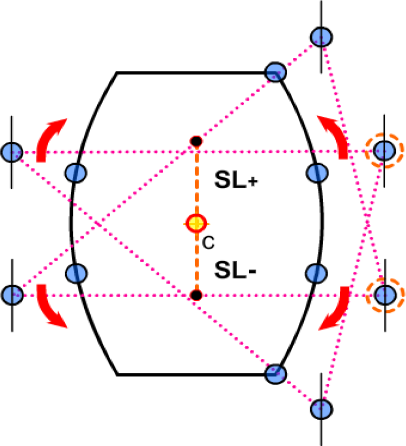
In this paper we assumed smooth terrain. Stability on rough terrain is difficult to measure. Stability margin is one of the significant factors for robot gait plan. The robot discarded the damage leg and change the gait plan after the critical stability situation occurred. Theoretically, marginal stability (the center of gravity CG is at the support-polygon border) is still regarded as stable (Clark, J. E. 2004; Wang et al., 2006). But in real application, even robots are completely symmetrical shape, but because of some factors (for example: manual assembly error, parts materials, inequality, etc.) robot's center of gravity cannot be coincident with the geometric center. For that reason, we assumed stability limit (SL) little less than theoretical limit (Fig. 2). When continuous tripod gaits are used, usually no marginal stability will occur. Thus, minimum axial stability limit d min is in between the length of the interval [SL+, SL-]min. As shown in Fig. 2, SL+ is the front axial stability limit and SL- is the rear. As we can see in Figure 2, the standard stride length is 2S. The maximum swing for both the front and the rear leg is assumed to be S. This is the same for both a six-legged and an eight-legged robot. But the difference is in the space specified between the limit positions of the L2 and L3 legs. For six-legged robot, it is assigned as 1.75S, whereas for eight-legged robot, only 0.5S. This space is designed to avoid the occurrence of marginal stability, i.e., dmin=0.
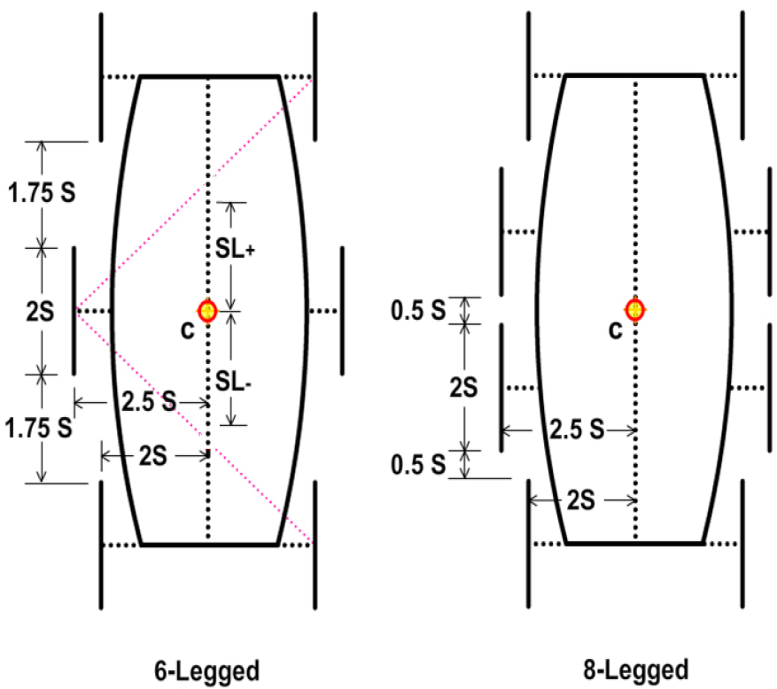
Hexapod and Octapod Robot Schematics. Maximum stride length is 2S; SL+ and SL- are the front and rear axial stability limit respectively.
Most insects can walk with the tripod gait, which is a fast and statistically balanced gait (SBG) for Hexapods. However, when one or more legs are missing, regular tripod gait is no longer possible. To get around this, a “common leg” needs to be shared in two tripod groups. We will explain more about “common leg” with an example in the following section
Alternative Gait Configuration
Consider a six-legged robot losing one leg R2 (shown in Figure 3). For Statically Balanced Gait (SBG), still two tripod groups of legs are required. But there are only five legs that mean we are short of a leg. To get around this, a “common leg” must be shared in both tripod groups.

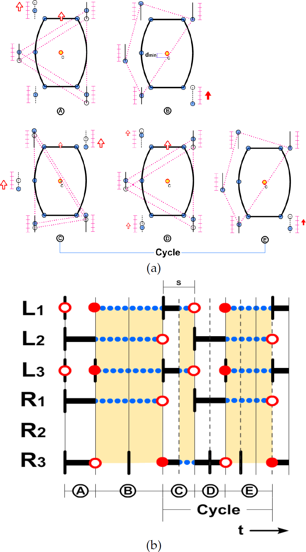
The 6-1-R2 case, as illustrated by robot schematics (a), and by the Enhanced Gait Chart (EGC) of the robot (b). A hexapod robot which has no R2 leg. In 2(a), hollow arrow indicates half step & solid arrow indicates full step (2S). Dash lines are indicate the support polygon. In each interval the robot travels a distance S.
Let's study the (6-1-R2) case at dmin = 0, as shown in the robot schematic in Fig. 3(a). A gait cycle is composed of a series of recurring walking steps, e.g., [A-B-C], as denoted by the circle capital letters A, B, C in the figure. The support polygon of each walking step is shown in dash lines connecting all standing legs. The center of gravity (c) of the robot can never fall outside the supporting polygon. Comparing the support triangles of steps A and C in Fig. 3(a), we see that leg R3 is the common leg. The vertical lines drawn beside the body are the possible displacement ranges of the legs, defined relative to the body. In each walking step, if a leg moves, it moves from the gray dot to the white dot in our schematics. We can see that the legs are originally placed at their neutral positions (in step A). When supporting legs move, they swing backward and their collective effort contributes to the forward motion of the body, as indicated by the hollow arrows in steps A and C. If the supporting legs do not have a motion in a step (Step B), they are called stationary legs, and this is stationary step. In stationary step, the robot remains in its previous position, and waits for a leg (normally the common leg) to adjust its position.
The non-supporting legs in either propulsive or stationary steps will make a forward swinging movement. They are referred to as swinging legs. Figure 3(b) showed the Enhanced Gait Chart (EGC) with respect to time, for the (6-1-R2) type at d min = 0. In an EGC, a hollow circle indicates the moment when a leg begins to leave the ground, and a solid circle shows the instant when a leg touches the ground. A gait cycle is evenly divided into a number of intervals, as in Fig. 3(b), each interval representing the time for a leg to swing, either forward or backward, a distance of S. Each grid in the horizontal axis represents the time for an S. The thick solid horizontal lines are the propulsive stroke. Blank gaps between hollow and solid circles are then the return stroke. The short vertical bars mean neutral positions of the legs except R2, since it is no more.
Intervals containing stationary legs are shaded and in such stationary steps, there are no thick horizontal lines, and the common leg is usually the only thing that moves. By counting the shaded intervals within a gait cycle, we define the progressive efficiency (PE) of an alternative gait for multiped robots with severed legs. PE is the ratio of the time used in non-stationary steps to the time of the entire gait cycle. For regular Hexapod robot, PE is 100%, because there are no stationary steps. However, for the (6-1-R2) case, PE is reduced to 50%. Half of the time is wasted in awaiting the common leg to return.
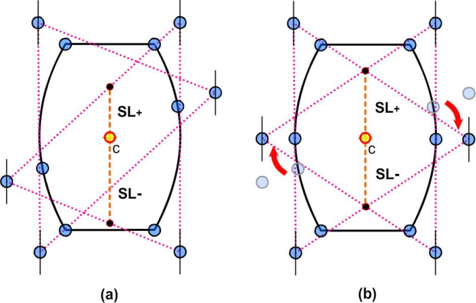
Now, let's consider the (6-1-R2) case at dmin = 0.5 S, as shown in the robot schematic in Fig. 4 (a). We investigated the movement of A to E and compared their position with Fig. 3(a) for d min = 0 value. In step B, we want dmin = 0.5 S, because L3 is supporting leg and it waits to return the common leg R3 then rise and ground same spot in step A. From the figure, we can see that stride length for L2, R1, and R3 group remains the same, but for L1, L3, and R3 it reduced to half of the original. From Figure 4(b), we calculated the progressive efficiency is 42% (
The 6-1-R2 case, for dmin = 0.5 S (a), and Enhanced Gait Chart (EGC) of the Robot (b). In 3(a), hollow arrow indicates half step (S), Solid arrow indicates full step (2S), Small hollow arrow indicates 0.5S and Small solid arrow indicates 1.5S
We generated a table for different gait sequence and relationship between dmin value with stride length and efficiency (see Table 1). From the study of this paper, we found that among the many possible alternative gait sequences resulting from leg defects, only a small number of them possess acceptable kinematic properties. Most others lack sufficient walking speed, or encounter marginal stability, or use small steps so that the steps become noticeably uneven. In some cases the ability to walk is completely lost.
dmin Adjustment in the relationship between Stride length and efficiency of the Multi-legged gait

Table 2 showed the summary of various types of severed leg gait patterns (Tsai, C. H. 2008). We used the unit for the longitudinal stability SL is S. The probability of failure in leg of Multi-legged Robot is high because of its complex structure and harsh working environment. So it is very important to solve the problem when failure occurred.
Summary for different gait sequences

For that reason, this paper proposes some changes in gait plan which are described in the following sections.
Fixed Position (FP) Adjustment strategy can be used to solve the low efficiency and stability of the damaged leg. Here we still use the model in Fig. 2 as a basis for measuring the stability. In (6-1-n), for both [3 | 2] (indicated that on the left it has 3 legs and right it has two legs) and [2 | 3] type, the normal state of the efficiency are same, so no need for conversion. In (6-2-n) series consists of four legs, [2 | 2] of the type, which has two pairs of symmetric, as discussed previously, the (6-2-L3R3) type requires a special arrangement in achieving leg transportation for FP.
There are two kinds of (8-1-n) types, both of the [4]|3] category, and tripod gaits can be used. The gait efficiency is one. Although there can be marginal stability in (8-2-L4R3) and (8-2-L4R4) types, they can be transformed into a better (8-2-L4R2) type. Similarly, (8-2-L2L4) and (8-2-L2L3) types can be transformed into (8-2-L1L4) to avoid marginal stability. For, (8-3-n) series of [2 | 3], or [3 | 2] of the type, depending on the efficiency can be divided into three types: 0.5, less than 0.2, and cannot go forward. Efficiency of 0.5 can be converted in to (8-3-L1 L4 R2) or (8-3-L2 L4 R2) type (both have same efficiency and stability), in order to enhance stability. Efficiency of less than 0.2, and cannot go forward type, can be converted in to (8-3-L2 L4 R2) type, in order to upgrade efficiency to 0.5.
Based on the above analysis, for any multiped robot having at least two legs on one side, it is possible to be transformed, via Fixed Position Adjustment, to a better configuration. This effectively solves the problem of robot disability due to loss of one or more legs leading insufficient stability or efficiency.
Non Fixed Position Adjustment (NFP)
In previous section, leg transportation to some fixed positions was discussed. However, it is noted that Non Fixed Position (NFP) adjustment of the leg positions is also possible with the sliding rail as shown in Fig. 1. For instance, an optimized position of a leg can be computed to obtain the best dmin value. Take (8-2-L2 R3) type in Fig. 5, for example, before making adjustments L3, R1, R4 constitutes the support polygon. Its front stability limit SL + = 1.52 S, rear stability limit SL- = 2.64 S, and dmin = 0.53 S for return trip. Then, we made it six legged standard form by using stepless transportation as shown in Fig. 5(b). Now, SL + and SL- become equal (both 2.08 S), and dmin = 1.08S and the whole system become more stable. Thus, this is the best way to adjust [3|3] type 6 legged robots.
Best combination for [3|3] type gait sequence
For (8-3-L2 L4 R2)-type, there is a triangle supported by a “peak” (indicated by dashed line circle) can be simultaneously affect the stability of front and rear side, but will not impact on the overall stability. Before adjustment (Fig. 6a) two vertices of the support polygon are L3 and R3, and L3 is the common leg. If we adjust L3 to increase the (SL-) of the (L1, L3, R3) group, conversely the (SL-) of the (L3, R1, R4) group is reduced. Thus dmin cannot be increased as a whole. However, (8-3-L2L4R2) type can be transformed into (8-3-L1L4R3) type of the same [2|3] category. The common leg is now R1, as shown in Fig. 6b, and the other vertices become L2 and L3. In this case R3 can be transported further backward, and the (SL+) for the (L3, R1, R3) group is increased from 1.25S to 1.5S. Then L3 is to be transported downward by 0.03S so that (SL+) and (SL-) become equally 1.51S. As for the (L2, R1, R4) group, its (SL+)=2.64S, and (SL-)=1.52S before adjustment. If we want (SL+) and (SL-) of this group to be as close as possible, without introducing interference, L2 needs to be moved downward by 0.53S, and (SL+) and (SL-) become 2.41S and 1.76S, respectively. This is now the optimal configuration for the [2|3] category.
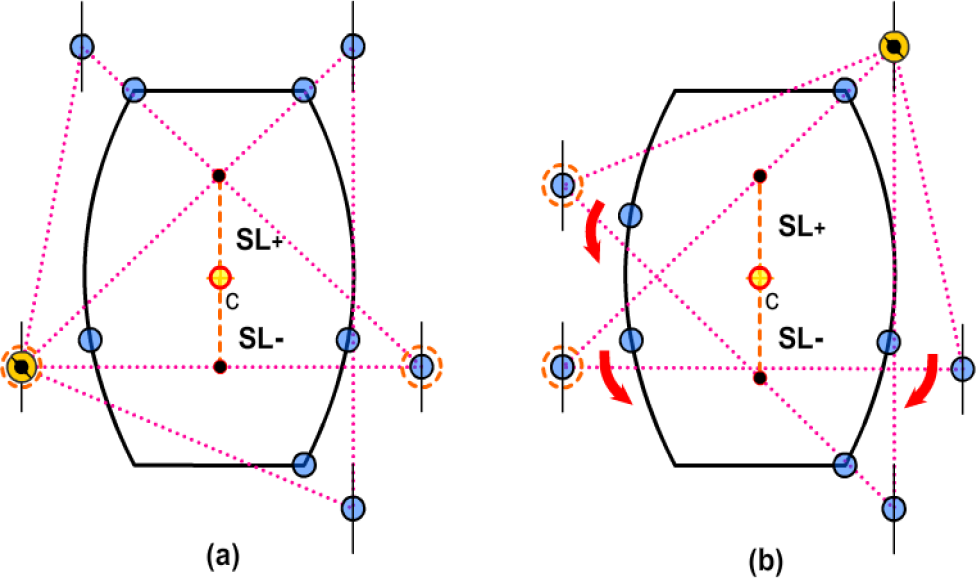
Best combination for [2|3] type gait sequence
As shown in Fig. 7, without leg transportation, the (8-2-L1L4) type is the best in [2|4] category. The rules of making adjustment are similar to those of the (L3, R1, R3) group in the (8-3-L1L4R3) type. The R3 leg in (L3, R1, R3) support polygon is first moved downward by 0.5S, making (SL+) increase from 1.25S to 1.5S, then L3 is move downward by 0.03S to equalize the two SL values to 1.51S. Since the other group (L2, R2, R4) is of opposite shape, so it is adjusted reversely. The minimal SL value (dmin) is thus increased from 1.25S to 1.51S. This is now the optimal configuration for [2|4] category.
Best combination for [2|4] type
From the above study, we can see that five legs [2 | 3] type is the best one. According to Inagaki (1997) analysis, the five legs when arranged in a regular pentagon, allows both groups to get a better stability. But it's purely based on the assumption of the model analysis, did not talk about the conversion scheme of physical robot.
As shown in Figure 8, is a circular hexapod Robot, so named because linking its legs constitutes a regular hexagon. A special characteristic of this robot is that it moves freely in all directions. Failure of any one leg will produce the critical stability Configuration (Figure 8b). By using circular guide robot and stepless adjustment, we converted it pentagon (Figure 8c), or a better arrangement (Figure 8d), to avoid the occurrence of critical stability condition.

Optimal configuration of Circular Hexapod Robot
This paper also proposes a procedure for a multi legged robot to resume its task after a serious leg failure. As shown in Fig. 9, whether the damaged legs can provide support has to be evaluated immediately after a breakdown is reported. The probability for a leg not being able to support is estimated as 67% (Fault at 2nd & 3rd Joint). So, damaged leg has to be severed. After leg severance the resulting leg configuration is compared with the optimal configuration of the category.

Procedure for a Multi legged robot to complete its mission after serious leg failure
Table 2 showed the probability of the occurrence of an optimal type. For instance, for (8-3-n) category, the occurrence for the best type is only 17%. However, non-optimal types can always be transformed to an optimal type if proposed Fixed Position Adjustment (FP) used. Moreover, after applying FP, the Robot gait can be adjusted more by introducing Non Fixed Position Adjustment (NFP). By following this procedure, a best leg configuration can be achieved which can maximize the stability and efficiency.
In real application, the construction and control method of multi legged robot is complicated. But if a leg failure occurred, then it needs some correction in gait to maintain efficiency. In some mission such as: planetary exploration, disaster response or antiterrorism mission; it is impossible to repair immediately after damage occurred. Then robot needs some alternative strategies to complete its mission. In this paper we propose a removable sliding leg approach to solve this problem. We focused on “Severed Leg” scheme and “Sliding Leg” approach to maintaining the efficiency and stability of robot. Because, damaged leg can produce some unwanted side effects to other legs and the robot system. Thus, it can be a good practice to discard the damaged leg and slide to better position of other legs by the command of operator to get optimum alternative gait configuration. For gait adjustment, we proposed Fixed Position Adjustment (FP) and Non Fixed Position Adjustment (NFP). By taking the proposed Fixed Position Adjustment (FP) and Non Fixed Position Adjustment (NFP), the multiped Robot can overcome any fault event and maintain stability and efficiency. Moreover, we studied the use of removable sliding leg approach on hexapod and octopod robots with leg failures. Based on leg sequence, stride length, longitudinal stability and efficiency, alternative gaits are evaluated. In addition, we recommended tables for different gait sequence with progressive efficiency and a procedure for a multi-legged robot to complete its mission after serious leg failure happened. These tables and procedures can provide options for alternative gait and information about certain damaged leg. It is therefore advisable for a robot designer to have these preferred gaits programmed into the robot's memory. Thus in an adverse condition, it will know which alternative gait pattern it should turn to.