
Abstract
By analysing the dynamic principles of the human gait, an economic gait-control analysis is performed, and passive elements are included to increase the energy efficiency in the motion control of active orthoses. Traditional orthoses use position patterns from the clinical gait analyses (CGAs) of healthy people, which are then de-normalized and adjusted to each user. These orthoses maintain a very rigid gait, and their energy cost is very high, reducing the autonomy of the user. First, to take advantage of the inherent dynamics of the legs, a state machine pattern with different gains in each state is applied to reduce the actuator energy consumption. Next, different passive elements, such as springs and brakes in the joints, are analysed to further reduce energy consumption. After an off-line parameter optimization and a heuristic improvement with genetic algorithms, a reduction in energy consumption of 16.8% is obtained by applying a state machine control pattern, and a reduction of 18.9% is obtained by using passive elements. Finally, by combining both strategies, a more natural gait is obtained, and energy consumption is reduced by 24.6% compared with a pure CGA pattern.
1. Introduction
The term exoskeleton is usually used to describe a wearable device that augments the user's strength and endurance, whereas the term orthosis is typically used to describe a device that is used to assist a person with a limb pathology [1]. When designing a lower-limb active orthosis, two fundamental issues must be taken into account: stability and energy consumption. The energy required for the extended operation of these devices exceeds that of a portable battery pack; this is currently the greatest obstacle to achieving their practical application. A research device like Vanderbilt Orthosis [2] provides approximately one hour of autonomy, while commercial lower-limb orthoses, such as Rewalk (Argo Medical Technologies [3]) and eLEGS (Berkeley Bionics [4]), provide eight and six hours of autonomy, respectively.
The motion control of active orthoses has traditionally been based on the rigid tracking of CGA reference patterns, typically resulting in high power consumption. A series of strategies and devices are then implemented to reduce energy consumption based on this trajectory generation control. Based on the study of passive and high-efficiency biped robots [5, 6] various methods to increase the energy efficiency in an active orthosis have been proposed:
Utilize elastic mechanisms to store and release energy.
Transfer energy between joints through bi-articular linkages.
Reduce collision costs by implementing impedance control.
Reduce collision costs upon heel strike by powering the previous push-off at the ankle.
Utilize passive pendulum dynamics during swing and stance.
Lock selected joint during certain phases of motion.
Locate more mass (actuators or other systems) near the hip, reducing the inertia in more distal limbs.
These strategies are being analysed by the Spanish National Research Council (CSIC) to further implement the ATLAS orthoses [7] (see Figure 1). Our previous work has been focused on Points 2 and 7 to reduce energy consumption and achieve a more natural gait in ATLAS [8]. In this paper, the proposal for energy-savings is focused on Point 5, designing a gait pattern that takes advantage of the inherent dynamics of the legs, and on Points 1 and 6, introducing passive elements attached to the limbs, either as springs or mechanical locks at the joints.

Front and back view of the ATLAS exoskeleton.
These strategies have been optimized by implementing a dynamic simulation, thereby evaluating the effectiveness and validity of the underlying ideas.
This work is focused on the sagittal plane motion of the hip, knee and ankle joints because most energy consumption occurs in this type of movement [9]. Background on the economic gaits used in this study is introduced in Section 2. The configuration of the biped robot used in the simulation is presented in Section 3.1; the methodology is presented in Section 3.2. Section 4 presents the results from the implementation of a passive gait, and Section 5 presents the results from applying passive elements to the joints. In Section 6, the viability of combining both techniques is analysed and the energy consumption data are shown. Section 7 evaluates the practical feasibility of the proposed ideas, and Section 8 lists the conclusions.
2. Background on gait pattern analysis
The traditional approach to economic locomotion has been described as “the six determinants of gait theory” [10]. In this approach, the height of the centre of mass (COM) of the body must be constant. However, some studies show that walking with voluntary reduced displacement increases energy expenditure [11]. To reduce the COM vertical excursion during the stance phase, the knee must be flexed, thus requiring extended torque to support the body weight. Additionally, during the swing phase, it is necessary to avoid the shock of the feet impacting the ground, requiring a broad sweep angle of the joints, which also produces an increase in torque.
Contradicting and coexisting with the “six determinants of gait” theory, the inverted pendulum walking model establishes that the support leg acts as an inverted pendulum by locking the knee, while the swing leg acts as a simple pendulum [12]. Mechanical energy is conserved in a pendulum, requiring no further mechanical force to produce motion along an arc. In principle, no mechanical force is needed to move the body, and no torque needed to support its weight. Longer and faster steps similarly require no effort. Nevertheless, as the speed of the gait increases, the stance leg appears to behave less like a pendulum. In this theory, a double-support phase (in which a pendulum cannot swing) is not taken into account, obviating the heel-strike collision. Based on the pendulum analogy and including the heel-strike collision, McGeer [13] conceived and designed machines that could walk down a ramp with passively stable locomotion. Passive dynamic locomotion incorporates passive dynamics to achieve low energy consumption, regardless of whether active power or control is applied [14].
In a human gait stance, a double-support phase can be seen as a transition from one pendulum to the next. At the heel strike, the leading leg exerts negative work to redirect the COM velocity. To achieve a steady speed, the trailing leg must exert a positive work. The power consumption from both limbs in this redirection of the COM is referred to as the step-to-step transition cost, and is the major determinant of the mechanical work involved in walking.
The positive work can be applied at any time during the step. Energy to reduce the collision losses at the heel strike may be supplied by pushing off at the ankle or powering at the hip, but applying the momentum at the ankle requires a quarter of the energy [15]. To avoid collision losses, the force required to redirect the body COM must start immediately before the heel-strike collision. Figure 2 shows that if the redirecting force P is exerted just before the heel strike, the speed v−cdm is reduced, and less energy is required to redirect the COM [16]. The positive force P must be introduced at just the right moment to compensate for the negative force S. If force P is applied after the heel strike, the speed v−cdm will increase and the offsetting force S will be higher.
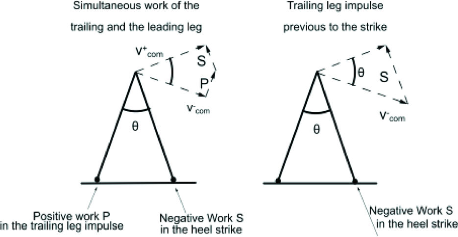
Simultaneous positive and negative force by the trailing and leading limbs during double support.
This dynamic walking approximation explains why wider steps increase the energetic cost: a greater directional velocity change is required. If, however, one increases the step frequency, more energy is consumed by the swinging leg. During a double-support phase motion, the trailing leg provides nearly all the positive work, while the leading leg provides the negative [16].
A discrepancy is found when analysing the vertical displacement of the centre of mass and the ground reaction force in experimental human walking, and comparing these features with those obtained in the inverted pendulum model. The analysis reveals that human legs exhibit a compliant behaviour during walking and running motions [17]. The stiffness of the legs varies with the walking speed [18]. This rebound performance is related to energy consumption. Energy can be elastically stored and help redirect the centre of mass in a step-to-step transition. Some models show that even without elastic elements, it is energetically beneficial to perform the collisions in a pseudo-elastic manner [19].
3. Problem approach
3.1 Simulation set-up
To verify the effectiveness and validity of the underlying ideas, a simulated biped robot is used. Subsequently, more efficient ideas will be implemented in the ATLAS orthosis. The ultimate goal of the ATLAS project is to design an active orthosis that enables a quadriplegic girl to walk. Therefore, masses, lengths, centres of mass and moments of inertia have been adapted to the patient in the simulation with the features shown in Table 1, following the estimations and adjustments given in [20] for the body inertial segment parameters (BISPs).
Physical parameters of the simulated biped robot.

To estimate power consumption, a biped robot has been designed using a robot dynamics simulation package (Yobotics SCS [21]). Through the optimization of mechanical power, different techniques are used to reduce energy consumption and analyse its implementation in the active orthoses. Figure 3 shows the CGA pattern on which we based the reduced energy consumption. It begins with the heel strike at the beginning of the stance. When the toe lifts from the ground at 62%, the stance phase ends and the swing phase begins.

Biped walker for the simulated gait and CGA pattern.
3.2 Measuring gait energy expenditure
As discussed earlier, traditional orthoses base their movement on the tracking of CGA patterns, usually by implementing a PD control strategy. Therefore, some pre-established and normalized angles and velocities, adapted to the height and weight of each user, are used as reference angles and speeds in each actuator, performing a torque as follows:

where θreal and
Therefore, the mechanical power consumed in a time T is given by:

where ωij(t) is the angular speed and τij(t) is the torque at the joint j of leg i.
The mean velocity could differ in each experiment. For this reason, a non-dimensional parameter is considered for comparison purposes, which is the specific resistance:

where E is the energy required to travel a distance L by a vehicle with weight W, P is the power consumed and v is the speed of the vehicle. The specific resistance considers the power consumed per unit of mass and unit of speed.
4. Energy-efficient gait pattern
This gait tracking of a CGA pattern has been implemented in the simulation. Kp and Kd gains have been tuned but remain fixed during all the gait cycle. The power consumption has been measured and the specific resistance has been calculated. A specific resistance of 1.13 has been obtained. This value will be used as the comparison reference for the rest of the experiments.
Based on the pendulum model for the gait [12], the inherent swing properties of the leg must be taken into account to reduce the energy expenditure while the legs follow the desired trajectory. Once the swing phase begins, the leg continues its trajectory with little energy intervention. In the single-support phase of the gait, the biped robot behaves as two coupled pendulums formed by the stance and swing legs. The swing phase is divided into three sub-phases. In the early swing, a constant torque is applied to both the hip and knee joints by means of a ballistic approach until each limb reaches the necessary speed [22]. In the middle of the swing phase, the hip and knee move freely, requiring almost no torque. At the end of the swing phase, the PD controller is used at the joints to achieve the desired posture at the moment of touch-down.
Each leg will have a simple state machine, and in each state different control strategies will be used (see Figure 4 (a)). Table 2 shows the energy consumption from applying this control strategy and the reduction achieved over the pure CGA pattern PD control.
Results from applying a passive control strategy.

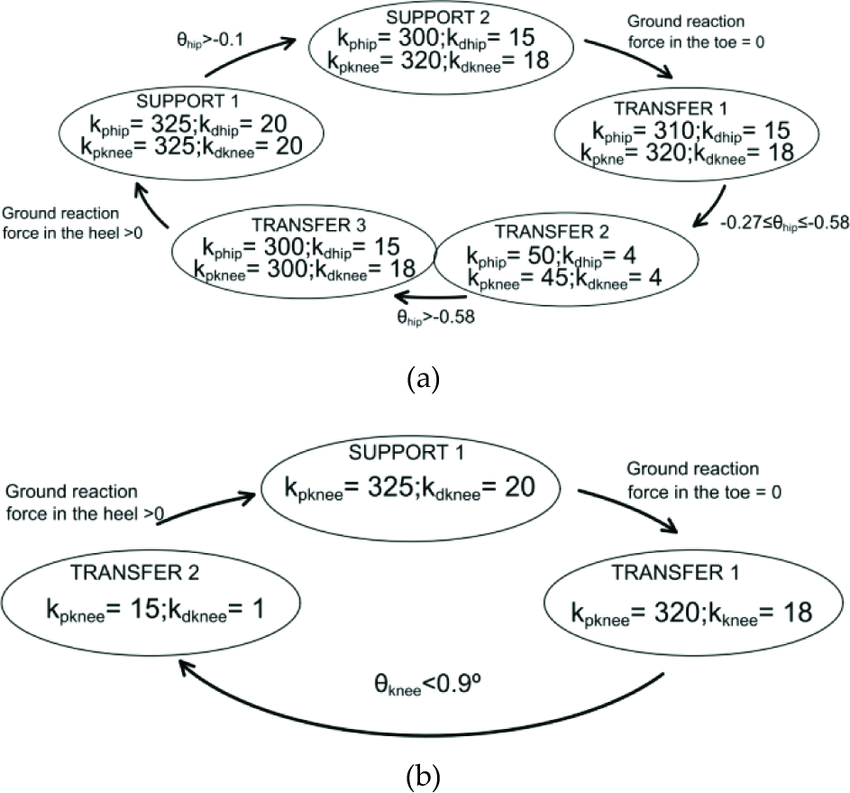
State machine controller. In each state, the PD constants and the transition condition are shown (a) for hip and knee and (b) for the knee.
The thigh and the shank move independently, with each reaching its peak kinetic energy at a different point of the gait cycle (see Figure 5).

Gap in the maximum kinetic energy in thigh and shank.
We have achieved a more efficient control algorithm by implementing two state machines, one for the hip, shown in Figure 4 (a), and one for the knee, shown in Figure 4 (b).
Table 2 shows that with this new strategy a reduction in mechanical energy expenditure of 16.8% is achieved.
This section focused on the active control of the hip and knee to reduce power consumption. The ankle can also be controlled through passive elements that provide ground clearance. This will be analysed in the next section.
5. Including passive elements
Human tendons are passive elastic elements that store energy and release it without metabolic cost. In the ankle joint, more than 60% of the energy required for locomotion is transferred by tendons [23].
By analysing the biomechanical features of the clinical gate analysis (CGA) of a healthy individual, one can reduce energy consumption through the use of passive elastic elements. The data gained from the study of a low-speed walking gait show that the hip and the ankle joints have periods of negative power followed by a period of positive power. A spring could store energy during the negative power period and release it during the positive power period. Moreover, power at the knee is predominantly negative, meaning that it primarily dissipates energy. The incorporation of a knee brace may provide some braking or damping elements.
5.1 Incorporating hip and ankle springs
The use of springs at the ankle and the hip has been analysed in the simulation. From the torques τ and the angles θ in these joints obtained from the CGA, the mechanical power computed from equation (2) has been minimized, taking into account that a torsion spring exerts torque if the joint ankle exceeds a threshold angle θthres. This torque is given by:
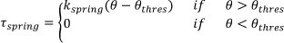
where kspring is the spring constant and θ the joint angle.
Making use of the MATLAB function fminsearch with these CGA values, statically optimal values for the spring constants and threshold angle are obtained and shown in Table 3.
Values for spring constants and threshold angle in hip and ankle joints.
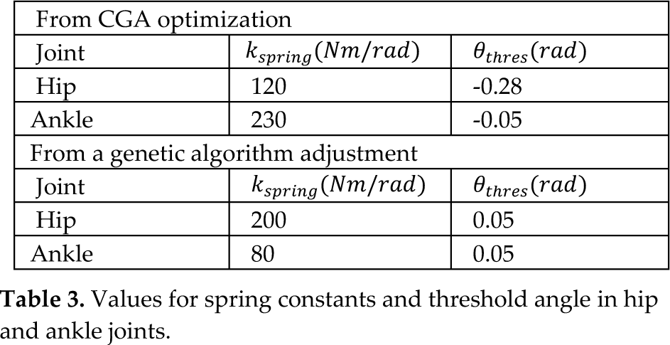
In this static optimization, it is assumed that the kinematics of the gait do not change when including passive elements. However, when these springs are introduced in the simulated biped, it is observed that although the power consumption is reduced in the joint in which the spring has been added, the rest of the joints are stressed, and the overall power expenditure increases. Working from the static optimized values, a heuristic adjustment based on genetic algorithms has been created, and the values for spring constants and threshold angle are shown in Table 3. Table 4 shows the reduction in energy consumption from incorporating a spring at the hip, at the ankle and at both locations.
Results applying passive elements.
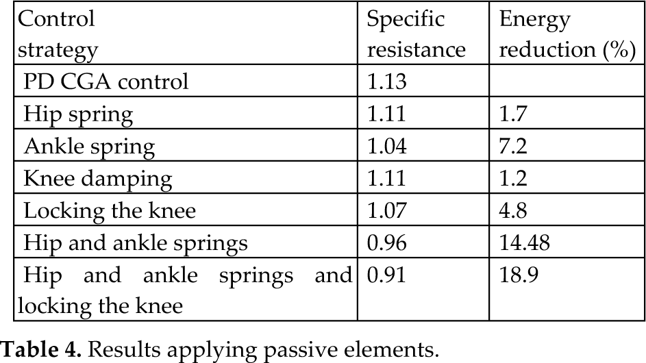
Figure 6 shows (in red) the torque exerted with a pure CGA control, with an included spring (in green) and the torque exerted by the spring (in black), at the hip and ankle. Note the significant reduction in energy expenditure when springs at the hip and ankle are working together, demonstrating the synergy between these joints.
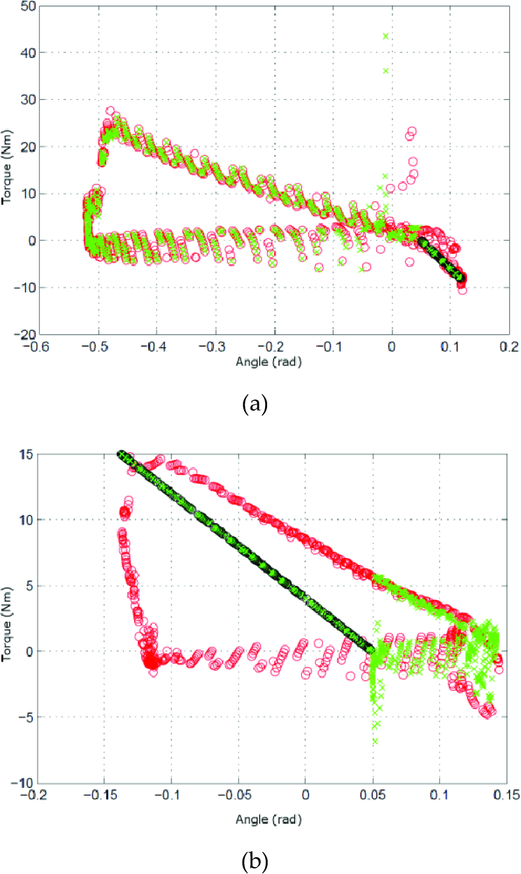
Spring torque. (a) Hip, (b) Ankle
Elastic elements do not ordinarily incorporate electronics, resulting in a premature release of recycled energy. Some devices [24] incorporate mechanisms that release energy at the exact moment of the ankle push-off, thereby consuming 10% less energy than with the use of the spring alone.
5.2 Damping at the knee
As previously mentioned, the knee dissipates energy through most of the gait cycle. The use of a dissipative device could help save energy during knee braking. The torque exerted by a damper, without taking hysteresis into account, is as follows:

where B is the damping constant and
As in the previous subsection, an optimization has been performed with MATLAB based on the CGA angles. With this static optimization, a damping constant of B = 3.8 Nms/rad has been applied to the range of the gait cycle from 55% to 64%; this part of the gait corresponds to the toe-off phase. If the damping coefficient is increased during the toe-off phase, the foot will not achieve ground clearance and the biped will stumble against the ground, making the static theoretical results misleading. Therefore, the damping constant and the range of application in the gait cycle have been obtained with genetic algorithms. Table 4 shows that the energy reduction with a constant B = 4 Nms/rad during the 15% to 35% portion of the gait cycle is 1.2%.
Previous studies [25] using magneto-rheological damping at the knee have not achieved energy reduction and have actually increased metabolic rate consumption. The causes for this increment are the additional weight of the passive devices and a non-zero introduced friction from the magneto-rheological damper in off state.
5.3 Introducing a lock at the knee
By examining the gait, it is observed that in some phases the knee angle is almost constant. A lock has been considered for blocking the knee when the swing leg moves forward and when the support leg is in the single-support phase. Adjusting the activation range of the lock via genetic algorithms, we learn that the lock can be engaged from 30.3% to 40.2% and from 67.1% to 85.2% of the gait cycle. This lock of the knee results in an energy consumption reduction of 4.8%.
After analysing the benefits of each passive element (springs, damping and brakes), an analysis is performed to consider the combined energy-saving benefits of all these mechanisms. Implementing all the passive elements in the dynamic simulation achieved a reduction in energy consumption of 18.9%.
6. Passive walking and passive elements together
In an active orthosis, all the power must be provided by the actuators. If the goal is reducing energy consumption, the next logical step is to combine a passive control pattern with passive elements.
The control pattern described in Section 4 will be used with a finite state machine, but now the response in each sub-phase will be changed.
In the SUPPORT 2 phase (see Figure 4), most of the work required from the actuator is supplied by the spring at the hip, so no actuator torque is necessary. In the middle and last phases of the swing (the TRANSFER 2 and 3 phases in Figure 4), a passive control scheme is applied to take advantage of the thigh inertia.
At the same time, if a knee damper is included in the early stance a state machine can be implemented in mid-swing to exploit the potential energy stored, reducing the actuator consumption.
Figure 7 shows the finite state machines employed for the incorporated hip and knee passive elements.
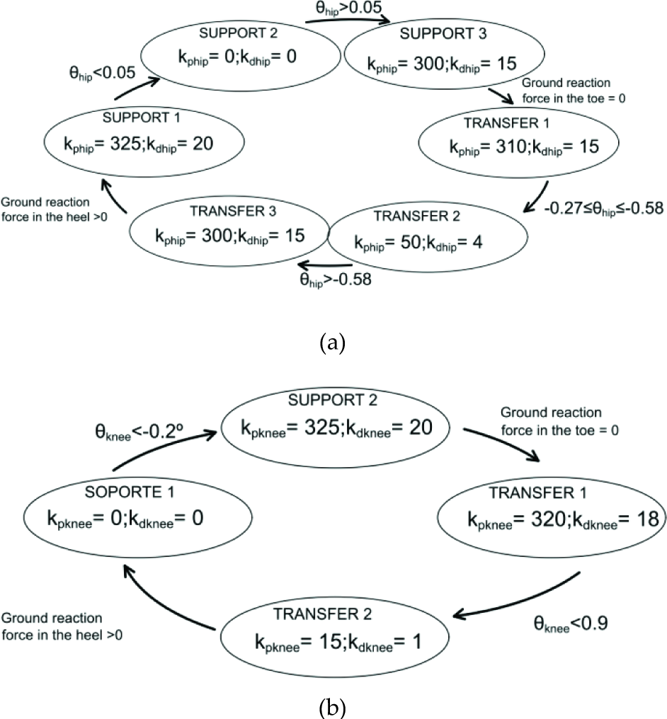
Finite state machine with passive elements at the hip. (a) At the hip, (b) At the knee
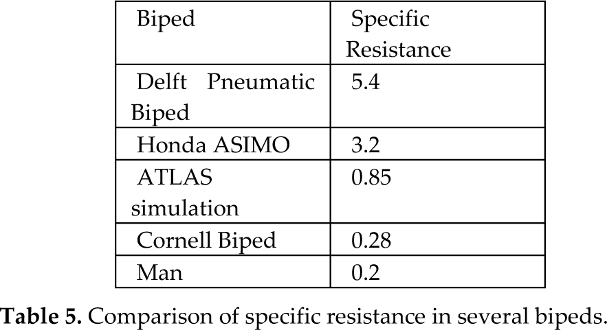
Energy expenditure is reduced by 24.6%, achieving a specific resistance of 0.85 when passive elements are combined with a strategy of passive control. Table 5 presents a comparison of the specific resistance of several bipeds [26]. From an energetic point of view the obtained results are located between passive robots like Cornell Biped and actively controlled robots like ASIMO. This comparison should be analysed taking into consideration that our results are based on simulation rather than on a real robot where mechanical efficiency and friction increase the specific resistance. Moreover, different robots have different actuated degrees of freedom, which affects power consumption.
Comparison of specific resistance in several bipeds.
7. Feasibility of the presented proposals
To incorporate these approaches into reducing energy expenditure in gait execution, some points must be taken into account:
An active orthosis must be designed as a whole; electrical and mechanical systems must be integrated to achieve a specific motion control.
Rigid actuators are not ideal for walking with real-world physical interactions
The proposed motion control approach, in which kinetic and potential gait energy is exploited and springs are used to store and release energy, is not achievable with rigid actuators.
Therefore, the proposed idea in this article requires the ability to adjust joint stiffness. The concept of bipeds changing the stiffness of their joints is not new [6] and some variable stiffness actuator designs have been proposed [27]. However, in the design of a wearable active orthosis, the size and weight of the actuator is a main design parameter. Therefore, pneumatic compliance controller designs [28] are not feasible because of the need for an air compressor and a distribution system. Other proposed mechanically controlled approaches, such as AMASC at Carnegie Mellon University [29], MACCEPA at Vrije Universiteit Brussels [30], VS-joint and QA-joint mechanisms at the German Aerospace Centre (DLR) [31], or AwAS at the Italian Institute of Technology (IIT) [32], are too large or heavy for the required torques. Closer examination of the results obtained in this study (see Figure 7) shows that a continuous range of stiffness is not necessary for a walking orthosis. Discrete stiffness values at different phases are required. In our proposed gait, we discovered that only three stiffness states are necessary:
Free limb motion to take advantage of the inherent dynamics of the limbs required negligible torque: null stiffness.
Spring recoil, to store and release energy: a specific spring stiffness.
Joint-locked-to-gear motor motion: infinite stiffness.
None of the above-mentioned variable stiffness actuators are able to provide these three states, so future developments in the ATLAS project will have to take these points into consideration.
8. Conclusions and future work
This paper presents an in-depth analysis of biped gait, as well as multiple options to reduce energy consumption in implementing these strategies for an active orthosis. First, based on a dynamic simulation of the different passive gait control schemes, energy consumption is reduced by 16.8%. Next, by incorporating the use of passive elements such as springs, dampers and locks, a reduction of 18.9% has been achieved. By combining both concepts, the energy consumption is reduced by 24.6%.
The results presented in this paper will be applied to the ATLAS active orthosis.
Footnotes
9. Acknowledgments
This work has been partially funded by the Spanish National Plan for Research, Development and Innovation through Grant DPI2010-18702, which has funded personnel costs, and by the AECID through Grant PCI-Iberoamerica A1/039883/11, which has funded equipment and consumable costs.