
Abstract
Although many papers have been published on visual tracking and visual servoing for vision-based robotics, there are only a few research projects studying using vision to improve standing and walking stabilization for legged robots. In this paper, we proposition a “Visual Lifting Bipedal Walking” strategy, which uses visually measured information to control the robot to keep a desired head-top's position/orientation in order to help prevent the robot from falling into unstable gaits, such as falling down on the ground or dangerous foot-slipping caused by gravity, unexpected coupling dynamics, etc.
1. Introduction
Humanoid robots are complex autonomous control systems that involve many technical issues which need to be solved, of which stable bipedal walking is the most fundamental. Therefore, this has been widely researched and a number of control approaches have been proposed to advance stable walking gaits.
The zero-moment-point (ZMP) approach is extensively utilized and has been shown to provide robust and effective locomotion for biped robots [1, 2]. The methodologies using ZMP firstly design a desired trajectory off-line and then derive body motions based on it. Since the natural dynamics of the robots –nonlinearity, coupling, changing of degrees of motion and the effects of the foot hitting the ground– are not considered, the ZMP methods often result in an unnatural-looking gait. Moreover, not every desired ZMP trajectory can be achieved because of the robot's kinematical limitation. In research [3] and [4] ZMP is not used and robot walking has been achieved by finding dynamically stable trajectories of joints through inverse kinematics calculations in advance from, e.g., the body's desired trajectory. This trajectory tracking approach makes walking gaits stable by following predetermined walking gaits, but it is difficult to realize adaptive walking in a complicated environment with unknown disturbances, where robots may encounter unpremeditated contact with, e.g., furniture and humans, or irregularities of the ground and having the controller reschedule the adaptive gaits' plan.
Therefore, online control methods for making the walking control system stable in the face of such disturbances have been intensively researched. Among them, walking control based on reflexive action is a method using sensory information to help the robot adapt to a time-varying environment. Qiang Huang et al. [5] have proposed a gait control consisting of a feedforward dynamic pattern and a feedback sensory reflex, which enabled a humanoid to effectively walk on unknown rough terrain and in an environment with disturbances. The sensory devices used in [5] include a foot-force sensor, body-inclination sensors and joint encoders.
As one of the most important sensors, vision has been used in lots of robot control research fields such as visual tracking and visual servoing (in which visual information is used to direct a manipulator toward a target object). Since the appearance of a manipulator is totally different from a humanoid with two legs, researchers have not yet fully considered how to use visual information to improve the walking stabilization for legged robots. However, if we do not consider the swing of the leg in walking, the body, from the foot (constricted to the ground) to the top of head can be considered as a linked manipulator. Thus, for this part of body, the “eye-in-hand” visual servoing concept can be used to keep a relatively constant position relationship between the head and a target object in the surrounding space, which is considered helpful in controlling the robot to prevent it from falling into unstable gaits, such as falling down to the ground or dangerous foot-slipping caused by gravity, unexpected coupling dynamics, etc…
Based on the above idea of using the visual servoing concept to control a humanoid robot, we newly proposition a “Visual Lifting Bipedal Walking” strategy which uses the vision sensory reflex to deal with the stabilization of the humanoid robot's bipedal standing and walking. Visual servoing can be classified into two major groups: position-based and image-based visual servoing [6]. Compared with image-based visual servoing, position-based visual servoing is more comprehensible, since a visual servo is more like a human-being in that it determines the object's position in a Cartesian coordinate frame and leads to Cartesian robot motion planning. Therefore, a position-based visual servoing concept is utilized in our research. We use cameras as the humanoid's eyes and a 3D model-based position measurement method that is proposed in our previous research ([7–9]) to observe an object that is set in the surrounding space.
One of the problems that have not been solved for online bipedal walking control concerns a singularity of the Jacobian matrix that occurs in walking robots. This problem occurs because the Jacobean matrix is determined as a function of the robot's shape and that is a result of the online dynamical motion, e.g., to avoid unpredictable disturbances, so the singularity cannot be prevented with preparation. Since this problem in stable walking is standing in the way of online adaptiveness, it will naturally be influenced by unpredictable disturbances so some researchers have started to work on how to retain stability [10, 11]. Considering this hazardous restriction: that the singularity of the Jacobian matrix connecting the velocity vector in Cartesian space and the joint velocity vector, prohibits the calculation of
2. Visual Lifting Bipedal Walking Strategy
Here, we use two cameras that are set as the humanoid's eyes to measure the position of an object set in the surrounding space and thus performing visual-feedback control to improve the humanoid's standing/walking stability.
We use a model-based matching method to measure the position of a target object denoted by φ based on the moving coordinates Σ H , which represents the robot's head. We use a “1-step GA” method to solve the model matching optimization problem to achieve online visual position estimation [7].
The desired relative position of Σ
M
(target object coordinate) and Σ
H
is predefined by a Homogeneous Transformation as
Hd

where
H
Here, the force exerted on the head to minimize the difference of the desired head position and the current position H

where
The joint torque τv to be input to realize the force

where
The above visual lifting bipedal walking strategy is depicted in Fig.1. If the robot's head stays in the position we have determined as the desired position (ΣH = ΣHd), then the head position difference δφ(t) is 0 and from Eq. (2) and Eq. (3) we know that there needs no joint torque to give a pulling force. However, if the robot's head position droops during the dynamic bipedal walking due to gravity or a dangerous slipping accident, then the head position difference δφ(t) is not 0 and the value can be calculated by Eq. (1). In this case, there needs to be a pulling force given by Eq. (2) to prevent the robot from falling down and a corresponding joint torque input to realize this force given by Eq. (3).
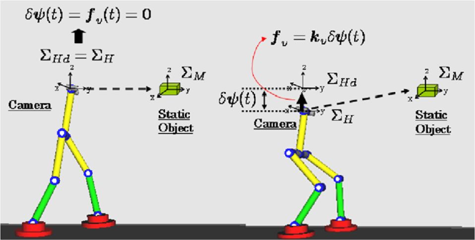
Visual Lifting Bipedal Walking Strategy
Here, τv is used to control the humanoid robot in keeping a stable body position by using visual feedback information to compensate for a falling action caused by gravity or an unpredictable dangerous slipping motion etc… In order to drive the robot to perform a dynamic walking motion, additional torque is needed to work on the thigh joint in order to take a step forward:
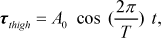
Where A0 is the amplitude that will influence the walking stride and T is the period of one walking cycle which influences the walking frequency.
τv and τthigh will be used together to control the humanoid robot in keeping a stable body position while walking forward. A simulation will be conducted to confirm the effectiveness of our proposed control method and the result will be shown later in this paper.
3. Bipedal Walking Model
The humanoid robot consists of a body, legs and eyes (Fig. 1) and has 10 degrees of freedom. Each link has a mass m, a length l, a radius of link r and an inertia moment I and each joint has a viscous friction D. When the robot walks forward the robot is getting closer to the static target object so it is necessary to change the position of the cameras to keep the object always in the view of both the left and right cameras. Therefore, the cameras are rotated about the z -axis to change eyes' gazing direction.
3.1 Dynamics of Walking
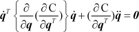
The equation of motion that includes point-constraint conditions, including contact-friction is written as:

In addition, C is defined as a point-constraint condition C(
Abbreviating the coefficient vectors of

The size of matrix
3.2 Walking Style Representation
The walking sequence of the flat-foot is more complicated than those of the point-foot and the round-foot, because each flat-foot has three contact cases: heel-contact, toe contact and foot contact. As shown in Fig. 2, there are several walking styles (I), (II), … (V) in the walking sequence. A walking process may not include all these styles; moving from which one to which phase of the motion depends on the equation of motion and some predefined conditions i.e. shape of the ground, size of the foot and so on. All dynamic parameters can affect the variety of the walking gait's motions.

Style transition diagram for bipedal walking
Let the forward leg be expressed by “FL” and the backward leg be expressed by “BL”, we can describe the characteristics of each walking style as follows:
Link-0 is surface-contacting without slipping; regarded as a part of ground.
Link-0 is point-contacting, but the constraint condition for Link-0 need not to be incorporated like in Eq.(5), that is, the second and third terms should be eliminated, since the motion of Link-0 can be added to the equation of motion as an additional state q0, increasing the number of states of Eq(7) by one.
The heel of FL (tip of Link-6) is point-contacting and BL is surface-contacting which is the same as with (I). The constraint condition is required for the heel of FL.
The heel of FL (tip of Link-6) is point-contacting and Link-0 is rotating which is the same with (II). The constraint condition is required for the heel of FL and the angle of Link-0 should be considered. In this case, the left-hand side of Eq. (5) is identical to the one in Style II.
In this walking style, FL becomes surface-contacting and is regarded as a part of ground. BL is point-contacting under the constraint condition. The backward leg can be used for exerting torque via the ankle.
3.3 Transition Conditions among Phases
This change of phase means that the heel of the rear-foot detaches from the ground in Phase (I) or (III). Firstly, the reference coordinate of 1

Transition from (I) to (II) and from (III) to (IV)
Here, when the resultant forces that act on the rear/front of Link-0 are defined as


Thus, when the value of
When the heel of the forefoot touches the ground, the phase is switched from (I) to (III) or from (II) to (IV). Therefore, given that the z-axis of the forefoot's heel is defined as z6, the switching condition is z6 < 0.
When Link-6, defined as a lifting foot's link, becomes surface-contacting, the phase is switched from (III) to (V) or from (IV) to (V). That is, when qe = q0+q1+ … q6 is defined as the angle between Link-6 and the ground as shown in Fig.2, the switching condition is: qe≤0.
In phase (III) or (IV) Link-6 is renamed Link-6' since the robot's basic configurations of (V) and (I) are identical but the link's numbers are swapped over and derived from the left leg and the right leg being reversed. When the condition that the tiptoe detaches from the ground is satisfied phase (V) is switched to phase (I). In this posture, the constraint force
4. Stable Walking Simulation Results
In the simulation we use a triangle as the target for the robot to observe and the motion of the robot is controlled by the observation result (Fig. 4), this is somehow like the well-known “visual servoing” concept. However, the contribution of this kind of visual feedback control used here is newly proposed “to help the bipedal standing and walking stably by visual lifting” and the following simulation will show the effectiveness of our proposed approach.
The graphic presentation of the robot's motion is given by “Open GL” and the robot's parameter values used in the following analysis are shown in Table 1. Here the triangle is set in a plane parallel with the plane yoz of Σ W , the distance to the yoz plane is 4.5[m]. The gazing direction of the right camera is changed and turned to right in order to observe the target.
Physical parameter values in simulations

Here, the visual-based control method described in Section 2 is used. Firstly, the position of the target object is measured by cameras using a proposed model-based matching method [7, 8], which gives the values of
τv uses the visual feedback information to control the humanoid robot in keeping a stable body position and compensating for the falling action. However, to perform a bipedal walking motion, we need an additional torque τthigh to work on the thigh joint to take a step forward.
In this simulation, we input the thigh joint torque as:
The simulation results are shown in the following Figures (Fig. 5–Fig. 10).

Graphic presentation of bipedal robot and the “visual lifting” process

Head pose changing in the bipedal walking process by using “visual lifting control”. (a): Head trajectory of y-axis in Σ W ; (b): Head trajectory of z-axis in Σ W ; (c): Head pose changing, the angle rotates around x-axis of Σ W , represented by quaternion. The straight line in each (a),(b) and (c) figure represents the desired value that is given beforehand.
Figure 5 shows the head trajectory y-coordinate (walking direction) and z-coordinate (upright direction) values in the walking process. The straight line in figures (a), (b) and (c) represents the desired value. Figure. 5(a) shows that the robot is walking forward with distance of 16[m] in about 16[s], (b) shows that the head height is decreasing while walking from 6.5[m] to 6.3[m] in the first 1[s] and that the height has been retained during the rest of the walking process. From Eq. (2) and Eq. (3), we can find that the error of 0.2[m] is the minimum value to produce a joint torque τv input to provide a lifting force against gravity and keep the robot standing stably.
Figure 6 shows the measured walking performance results and the straight line in figures (a), (b) and (c) represents the desired value that is given beforehand. Since the y-axis of Σ H is the same direction as the z-axis in Σ W Fig.6 (a) corresponds to Fig. 5(b), leaving a constant error of 0.2[m]. All of the oscillations in Fig. 5 and Fig 6 are periodic with a small amplitude, which implies the walking is stable.
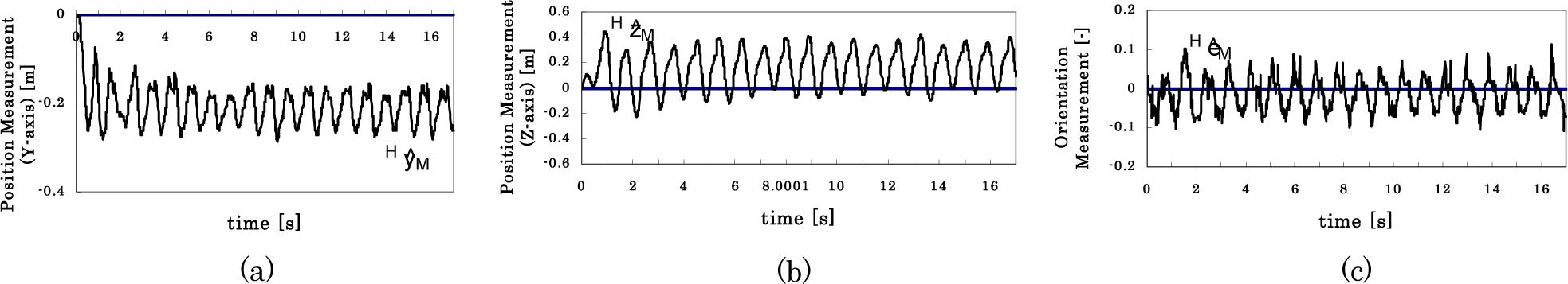
Measurement results in the bipedal walking process. (a): Position measurement of HyM; (b): Position measurement of HzM; (c): Orientation measurement of HεM, the angle rotates around x-axis of Σ H , represented by quaternion. The straight line in each (a),(b) and (c) figure represents the desired value that is given beforehand.
Figure 7 shows how the walking style changes in this simulation. It is a rhythmic motion that is changing by Style I –> Style III –> Style V with a period of 1[s]. Figure 8 shows the leg trajectory expressed by phase portrait; the relation of the thigh angle (the angle between the two legs) to its velocity. In the initial posture the thigh angle is 0[rad]. When the walking starts, one leg takes the first step with the thigh angle changing from 0[rad] to about 0.6[rad], then in the second step the thigh angle returns back from 0.6[rad] to 0[rad] and the following steps continue in the same manner. Figure 9 is foot trajectory on the ground. The distance between each point is almost equal so we can say that the walking is stable.
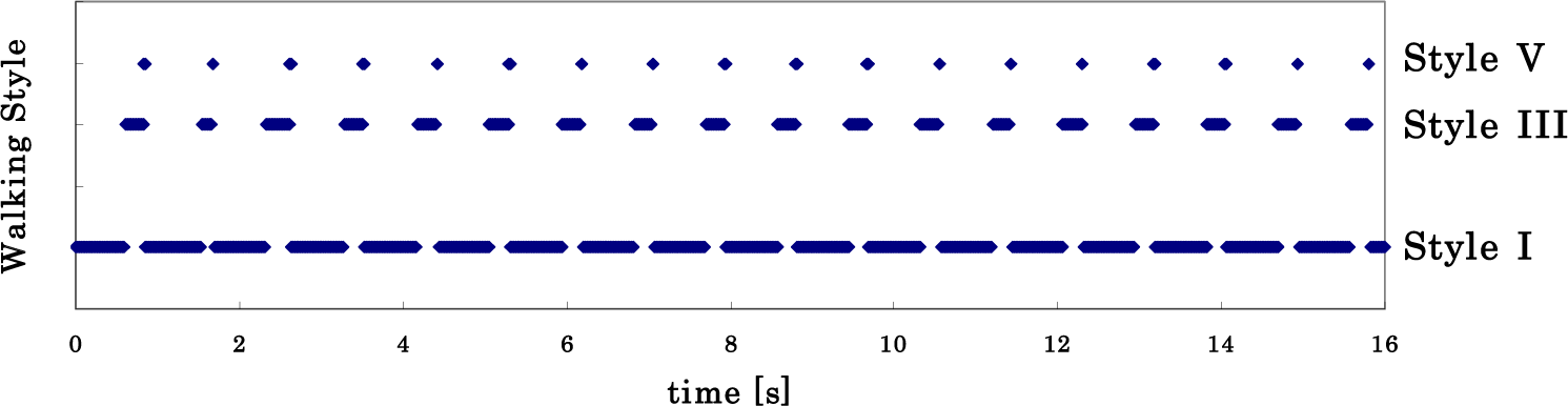
Walking style changing with respect to time.

Leg trajectory of dynamic walking, expressed by phase portrait.

Foot trajectory on the ground.
Figure 10 shows dynamic walking of the bipedal robot using the proposed “visual lifting approach”. The robot in the pictures describes stable dynamic walking with foot changes of Style I –> Style III –> Style V corresponding to Fig.7.

Dynamic bipedal walking by visual lifting approach.
5. Conclusion
In this paper, we proposed a “Visual Lifting Bipedal Walking” strategy, by using visually measured information to control a robot to keep a desired head position/orientation to avoid falling down.
Simulation results have shown that the proposed “Visual Lifting” control scheme based on the visual servoing concept is effective in preventing the robot from falling down due to gravity. By inputting an additional torque on the robot's thigh joint, we successfully performed a bipedal walking simulation and the result has shown stable walking.
In future work, we will consider how to calculate a suitable torque that works on the robot's thigh joint to perform stable walking at different speeds. We hope our bipedal robot is able to walk faster and faster, and finally run; different walking styles will have to emerge in this motion. Even this current kind of control is very difficult, it is interesting and challenging.
Footnotes
6. Acknowledgments
This work was conducted under the guidance of Professor Mamoru Minami from Okayama University, Japan. The authors are grateful for his helpful discussions.
This work is supported by National Natural Science Foundation of China (NO.61105029) and Shanghai Pujiang Program Foundation of China (NO.11PJ1403700).