
Abstract
The Zero Moment Point (ZMP) stability criterion has been broadly employed for walking pattern generation in legged robots. However, ZMP-based approaches usually ignore the presence of angular momentum in the system. This hinders the performance of the gait, especially against disturbances. In this work we propose an angular momentum controller that can be integrated into standard ZMP-based gaits. The experiments on a real Nao robot demonstrate that the use of the proposed angular momentum controller improves the stability of a walking pattern generator based on the preview control of the ZMP.
1. Introduction
In order to allow humanoid robots to participate in a broad range of everyday activities, it is necessary to develop smooth and reliable gaits. Although there has been an intense scientific effort in the development of stable gaits for biped robots, the balance control issue is still open.
Among the approaches employed to generate walking patterns we can distinguish two groups. The first one, that does not need any physical model of the robot, is based on central pattern generators that combine a set of empirically tuned oscillatory signals to create omnidirectional gaits [1, 2]. The second group, on the other hand, uses simplified physical models of the robot and stability criteria to generate the balanced walking pattern.
The most popular [3, 4] stability criterion is based on the Zero Moment Point (ZMP) concept [6]. The ZMP specifies the point on the ground where the tipping moment acting on the robot, due to gravitational and inertial forces, equals zero. This point can only exist within the limits of the convex hull of the support polygons, otherwise gravitational and inertia forces would induce a moment around an axis placed at the closest side of the convex hull.
Even though Inverted Pendulum ZMP-based approaches for walking pattern generation enjoy great success, they neglect the rotational dynamics of the robot. The control of angular momentum plays a fundamental role in biped balance, as has been pointed out in [5]. Thus, the lack of a system to control angular momentum handicaps the performance of gaits based exclusively on Inverted Pendulum and ZMP.
In this work we describe a simple closed-loop angular momentum controller that can be integrated into ZMP-based gaits. The control law is suggested by the analysis of the dynamics of the model and the controller is integrated into a walking pattern generator based on Model Predictive Control (MPC). The performance of the approach is validated on a real Nao robot.
This paper is structured as follows. After reviewing related work in Section 2, we analyse the rotational dynamics of the robot and derive a control law for angular momentum control in Section 3. Section 4 provides details on the integration of the controller with the MPC-based gait. To conclude, Section 5 presents the experimental validation of the proposed approach on a Nao robot and Section 6 discusses the results.
2. Related Work
The study of humanoid robot balance commenced in 1970 with the early works of Vukobratovic et al., who defined the ZMP and proposed its use as a stability criterion for robots [6]. Since the calculation of the exact position of the ZMP is a complex and computationally demanding task, robots are often modelled as an inverted pendulum, with all the mass of the robot concentrated at the position where the Centre of Mass (CoM) is located. The introduction of the 3D Linear Inverted Pendulum Mode [7], enabled representing the non-linear dynamics of the CoM using second order linear differential equations.
This simplification of the system dynamics permitted applying preview control theory to plan the trajectory of the CoM given a reference trajectory for the ZMP [4]. In [8] a slightly modified version of the preview control approach with reduced computing requirements is presented. In our work, we base the feedforward control of the trajectory of the CoM on [8], while a new angular momentum controller is introduced to incorporate feedback from the inertial unit.
Since the rotational dynamics play an important role in the stability of the gait, several approaches have been proposed to generate trajectories for the CoM that explicitly control the angular momentum of the robot [9, 10]. These approaches provide interesting tools to plan the trajectories of the CoM or even the limbs of the robots.
Most of these approaches have been tested only in simulated environments. However, some recent developments have provided impressive results also in physical robots. In [11] the stepping direction is calculated to ensure that the CoM trajectory will not diverge for a target ZMP when the robot is disturbed, but the approach is only tested on a still robot. Also in [12] good disturbance rejection is attained. In this case, the reaction of the robot is not based on a physical model but on biomechanically motivated strategies that are learned online.
Some of the closed-loop controllers that allow robust walking consist of estimating the real state of the CoM and using this estimate to update the feedforward controller based on the LIPM model [13] or on preview control of the ZMP [14]. A different feedback strategy is to modify the reference position of the ZMP [15].
In this paper, we seek a similar effect to [15], but instead of modifying the reference ZMP we are acting directly on the acceleration of the CoM. In this way, the angular momentum control does not depend on the effective tracking of the reference ZMP trajectory. In order to generate the control signal we use a P controller whose input is the angle between the sole of the support foot and the ground. This angle is estimated from the information provided by the inertial unit.
The use of P controllers based on the gyrometers' measurements has also been proposed in [16] and extended to a PID controller in [17]. In these works, however, the control signal modifies the ankle joints of the robots, which complicates the integration with ZMP-based approaches.
3. Angular Momentum Control
In order to use the LIPM model to generate walking patterns, the movement of the CoM has to be constrained to a plane that is usually parallel to the ground. For a balanced robot whose feet lie firmly flat on the ground, this fact involves the perpendicular distance between the sole plane and the CoM being constant. It is a common strategy [13, 14] to place the reference frame parallel to the sole and generate the walking pattern with constant height in this frame.
Nevertheless, unexpected disturbances may happen and tilt the sole. Under these circumstances, the Centre of Pressure (CoP) of the robot will move to one of the extremes of the sole and the robot will rotate around it, assuming that the torso of the robot stays perpendicular to the sole plane. If the magnitude of the disturbance exceeds a certain threshold the robot will tip over, but for moderate disturbances the sole of the robot will recover the flat position with a certain angular speed. At that instant, the CoP will jump to the opposite extreme of the sole. This extreme will be the new axis of rotation and the process will be repeated. For a perfectly rigid robot in a frictionless environment, the rotation around the extremes of the sole would generate a periodic oscillation for infinite time.
Real robots, on the other hand, suffer from friction that attenuates the amplitude of the oscillation in every cycle. However, the attenuation process is slow. For regular disturbances, the oscillations can be perceived during several seconds, as shown in Section 5. In order to adapt a ZMP-based gait to these oscillations, it would be necessary to estimate accurately the angle of the sole and the sensory-motor lag.
In this work we have adopted a different approach: we employ an angular momentum controller to enforce the attenuation of the oscillations and use the ZMP-based walking pattern generator for the feedforward control of the trajectory of the CoM.
Assuming a point mass robot placed at C(x,y,z) in a reference frame located at the projection of the ankle on the sole of the support foot, the torque that will modify the angular velocity of the sole is given by


The acceleration of the CoM affects to the restoring moment of the sole of the robot.


where θ is the angle between the sole and the ground around the y axis located at the limit of the sole xb, M is the mass of the robot and G the gravitation constant. The torque around xb resulting from these forces is

Our goal will be to manipulate the acceleration of the CoM, ẍ, to reduce the angular momentum of the robot:

At this point another simplification is made to the model. In regular configurations for the Nao robot, the range of x is limited to [30, 40] mm and the height of the CoM is fixed around 260 mm. Therefore, the moment of inertia of the robot I around the border of the sole does not change significantly during operation and we will consider it constant. In this way, we can state that the angular acceleration ̈θ is approximately proportional to the torque around the border of the sole xb.
In (4) we appreciate an instant contribution of the CoM acceleration ẍ to the torque around the limit of the sole, but also a contribution of x with the opposite sign. Consequently, there is a trade off between the short- and long-term impacts of the acceleration of the CoM on the torque around the border of the sole. If the magnitude and the duration of the control action are reduced, the acceleration term is dominant over the position offset. Hence, an appropriate control law for the acceleration of the CoM of our controller ẍc is:

where P is a positive definite constant. After integrating both members of (6) and discretizing with control period T:

The increment in the position of the CoM due to the angular momentum control is therefore:

Figure 2 illustrates the performance of the controller according to the model described above. In the first row, the oscillation of the pitch angle is perpetual in the open-loop mode, while it is considerably reduced under the action of the controller. The second row shows the torque around the limit of the sole that is in contact with the floor. It is interesting to notice that the magnitude of the restoring moment of the closed-loop signal is higher than that of the open-loop signal at the beginning of every oscillation, and that it becomes smaller when the angle of the sole approaches the horizontal position again. The third row displays the sagittal position of the CoM in the sole frame.

Simulated response of the angular momentum controller. At t = 0s a disturbance is simulated as a step increase in the angular speed of a standing robot.
As a side effect of the action of the controller there is a shift in the position of the CoM at the end of the process. In this way, to prevent limit situations of the kinematic chains of the robot, the action of the controller is limited to a certain threshold. In the next section we will explain the integration of the controller in a walking pattern generator that deals with the CoM deviations produced by the angular momentum controller.
4. Integration in Walking Pattern Generator
The angular momentum controller described in the previous section can be integrated into existing ZMP-based walking pattern generators. This is an important feature because these commonly used approaches have been intensely studied and have demonstrated its robustness.
In our work we use the efficient implementation of Model Predictive Control proposed by Wieber [8] to generate the trajectories of the CoM. The state of the CoM comprises its position, velocity and acceleration in a frame located at the projection of the ankle on the sole of the support foot. For a fixed height of the CoM and a certain control period, an optimum sequence of jerks (first derivative of the acceleration) of the CoM over a preview interval is calculated. The function that is minimized is a weighted combination of the sum of squared ZMP tracking errors and the sum of the squared jerks over the preview interval.
In every control cycle only the state of the CoM in the next cycle is calculated. The position of the CoM is delivered to the inverse kinematics module and the state of the CoM is used as input for the next time step.
To combine the advantages of the feedforward control provided by the MPC and the stability of the angular momentum controller, the control signal from the angular momentum controller is employed to shift the position of the CoM in the input state of the Model Predictive Control, as displayed in Figure 3. In addition, it is necessary to take into account the sensory-motor lag, which for the Nao robot is approximately four cycles.

The angular momentum controller integrated into the walking pattern generator.
The model predictive controller minimizes the tracking error of the ZMP trajectory, but it does not assure any bound for the tracking error. It is therefore necessary to develop a strategy to design adequate ZMP trajectories for a given state of the CoM. Moreover, as we have seen in the previous section, the cost of using the angular momentum controller is a deviation in the position of the CoM, which can cause the ZMP tracking error in the MPC to increase.
In our approach, the target ZMP is set to a fixed point on the sole of the support foot. There is therefore a direct relationship between the reference ZMP trajectories and the footstep planning. To prevent large ZMP tracking errors, different strategies are adopted in the lateral and the sagittal components of the movement. While for the lateral dimension the duration of the steps is modified to ensure an appropriate state of the CoM at the end of the step, in the sagittal dimension the stride sizes are bounded according to the state of the CoM at the beginning of the step. The range of possible stride sizes in the sagittal dimension is calculated with


where smin and smax are the limits of the range of possible stride sizes, Tstnde is the default duration of the stride, xm and xM are the flexibility margins, and

being T the control period and xAM the control signal obtained in (8).
5. Experiments
In order to validate the performance of the angular momentum controller, two experiments were realized. The goal of the first experiment is to measure the time needed by the system to recover from a disturbance in the sagittal plane. In the second experiment, on the other hand, the stabilization performance during undisturbed forward gait was evaluated.
The platform employed for the experiments is the Nao humanoid robot. Nao is a 57 cm tall humanoid equipped with a 500MHz processor. In the version used for this work, this robot has 21 DoF (five in each leg, one common to both legs, four in each arm and two for the neck).
Since the computing power of the platform is reduced, approaches with high CPU requirements are not affordable. Moreover, the significant backlash poses a challenge to control systems.
5.1 Disturbance Recovery
To evaluate the disturbance recovery performance of the system, a controlled force is applied on the chest of a standing robot to make it swing in the sagittal plane. Once the disturbance is executed, the time required by the system to return to the still upright pose will be used as a disturbance recovery performance indicator.
A perfectly rigid body that receives a disturbance in a frictionless environment would swing perpetually. The real robot, on the other hand, stabilizes after a few seconds mainly due to the damping effect provided by the limited torque of the actuators. The challenge for the angular momentum controller is to reduce the stabilization time.
The disturbance applied to the robot is generated by a 450 gram mass hanging from the ceiling in a pendular configuration. The mass is swung to the side and subsequently released to impact on the chest of the robot. The magnitude of the disturbance is calibrated to cause a 10 degrees inclination of the torso pitch angle.
In the upper graph of Figure 4, the evolution of the pitch angle estimated at the torso is compared for open-loop and angular momentum control configurations. The action of the controller reduces significantly the time required to recover the still position. While the open-loop mode needs 3.46 s to reduce the oscillation to a magnitude of 0.1 degrees, with the activation of the angular momentum controller the same result is achieved in 2.16 s. The reduction of the recovery time provided by the angular momentum controller is therefore 37%.

Performance of a standing robot that receives an impact to its chest. The upper plot compares the evolution of the torso pitch angle with open-loop and angular momentum control configurations. The lower plot displays the control signal of the angular momentum controller.
The lower graph of Figure 4 shows the control signal xAM that was defined in Equation (8). As we mentioned in section 3, the control signal is limited to a certain threshold to prevent excessive deviation of the CoM. In this plot it can be noticed that the signal is capped for pitch angles beyond 5 degrees.
Figure 5, on the other hand, reproduces the evolution of the system in the phase space for the same experiment. The horizontal coordinates represent the pitch angle of the torso, while the vertical coordinates represent the pitch velocity. Although the maximum angle reached by the robot is the same in the first peak after the disturbance, the angular momentum controller needs fewer cycles to recover the still state.

Performance of a standing robot that receives an impact to its chest. The evolution of the system in the phase with open-loop and angular momentum control configurations is compared.
To provide a graphical view of the performance of the controller, a similar experiment was recorded in a video and the filmstrips are displayed on Figure 6. In this case, the robot is pushed by hand on its back while it is walking on the spot. Again, the disturbance is executed both in open-loop mode and with the angular momentum controller enabled.
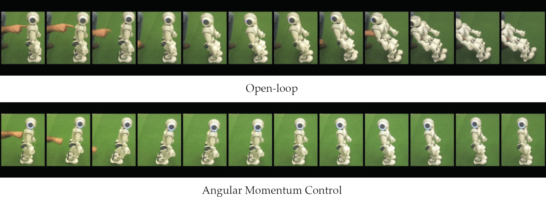
The robot is pushed on its back while walking on the spot. The sequences display 8 frames per second.
In the upper filmstrip, the robot is pushed forwards in open-loop mode and the restoring moment causes the robot to tip over backwards. Once the controller is enabled, the robot is able to keep balance even after a stronger disturbance, as displayed on the second filmstrip.
5.2 Gait Stabilization
In the second experiment, we recorded during 60 seconds the angular velocity measured by the gyrometers of the inertial unit while the robot was walking forwards at different speeds. To evaluate the performance of the controller in the sagittal dimension, we enabled the control system in the frontal plane and compared the gyrometer measurements in the sagittal dimension, both in open-loop mode and with the controller enabled.
Figure 7 shows the results of the experiments. Both in the case of walking on the spot and walking forwards at 0.04 m/s, the standard deviation of the pitch velocity of the torso is reduced with the activation of the angular momentum controller. When the forwards velocity of the robot is increased to 0.08 m/s, the robot becomes slightly more unstable with the angular momentum controller, while it is not able to keep upright in open-loop mode.
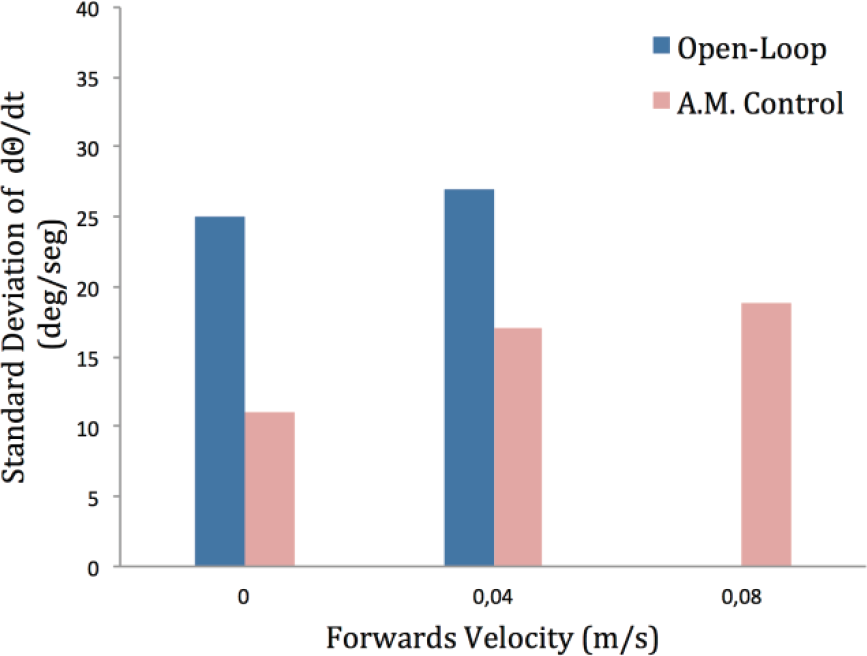
The height of the bars indicates the standard deviation of the pitch velocity of the torso for different forwards velocities of the robot. The open-loop result is omitted for forwards velocity 0.08 m/s because the robot is unstable.
6. Conclusion
In this paper we introduced a new closed-loop angular momentum controller that can be integrated into LIPM-ZMP gaits. The work has a strong focus on the performance of a real platform. In this way, several experiments are carried out on a Nao robot, where the improvement in stability is demonstrated. The input for the feedback controller is an estimation of the angle between the sole and the ground that is obtained from the processed measurements of the inertial unit.
The next stage of our work is to improve the physical model to represent more accurately the dynamics of the real platform by considering explicitly the existence of backlash. Subsequently, the new model will be used to improve the performance of the controller.
Footnotes
7. Acknowledgements
This work has been supported by the Spanish Ministry of Education, Culture and Sport through its FPU programme under grant AP2008–01816.