
Abstract
Humanoid robotics is unquestionably a challenging and long-term field of research. Of the numerous and most urgent challenges to tackle, autonomous and efficient locomotion may possibly be the most underdeveloped at present in the research community. Therefore, to pursue studies in relation to autonomy with efficient locomotion, the authors have been developing a new teen-sized humanoid platform with hybrid characteristics. The hybrid nature is clear in the mixed actuation based on common electrical motors and passive actuators attached in parallel to the motors. This paper presents the mechatronic design of the humanoid platform, focusing mainly on the mechanical structure, the design and simulation of the hybrid joints, and the different subsystems implemented. Trying to keep the appropriate human proportions and main degrees of freedom, the developed platform utilizes a distributed control architecture and a rich set of sensing capabilities, both ripe for future development and research.
Keywords
1. Introduction
The progress made in humanoid robotics research in recent years is remarkable. Demonstrations of working systems with anthropomorphic forms and sophisticated motion skills are driving forward a new generation of autonomous robots designed to cooperate and interact with humans [1-3]. In spite of recent advances, valuable and versatile platforms for research still imply prohibitive costs for many research groups aiming to perform activity on dynamic walking, sophisticated sensory-motor control or cognitive architectures. On the opposite front, recent innovations and technological solutions have opened up the opportunity for building robotic platforms that mimic the kinematics and kinetics of their biological counterparts. From the mechatronic viewpoint, the primary challenge is to balance the need for human-like behaviour with the reality of relying on current technology in materials, actuators, motor control, sensors and computation power, as well as with factors such as reliability, cost and availability.
The project underneath this specific work aims to develop stepped-up efforts in designing small-size humanoid platforms with innovative engineering solutions and commercial technologies able to open up a large range of future research possibilities. This paper highlights the research issues that have been raised during the project in order to coordinate and integrate the various subsystems that form the final mechatronic prototype. The work herein reported is guided by the experience gained from previous prototypes [4-6], as well as recent advances in actuation, sensor technologies and computational power. In the mechanical design, special emphasis has been laid on a new mechanical structure, designed from scratch in light and stiff materials, suited for the installation of linear elastic elements in a similar way to ligaments and muscles in the human body. For enhanced control power and versatility, the entire system is based on a hierarchically distributed architecture supported on a Controller Area Network (CAN) arrangement of microcontrollers with local decision capabilities (at the lower layer), but able to comply with global directives issued by a central unit based on an embedded computer system (at the top level).
The paper is organized as follows: Section 2 reviews the current research activity in humanoid robotics and our motivation and mechatronic design principles. Section 3 introduces the anthropometric concerns and details the mechanical design. Section 4 addresses the open problem of energy-efficiency and the hybrid actuation system proposed. In Section 5, we describe the different components of the humanoid robot with emphasis on the distributed architecture and the multimodal perception. Section 6 summarizes the results and concludes the paper.
2. Research in humanoids
2.1 Current perspective
There is considerable research work centred on the development of humanoid robots with human-like forms and movements. Most of the projects involving companies are still being actively pursued. The impressive designs and skills of Honda's P2, P3 and ASIMO robots represent landmark research work [3,7]. The HRP project involves efforts from the world of academia and industry which focused on the potential of real-world applications for humanoids [1,8,9]. The QRIO prototypes developed by Sony were targeted to develop robotics systems for entertainment by following up the success of the AIBO robot [2]. In recent years, several small-size valuable commercial platforms have also appeared suitable for research purposes (see, for example, [10]).
At the same time, the continuous progress in robotics technology has strengthened academic involvement. The activities at the University of Tokyo with a number of humanoid robots [11], at the Waseda University with the WABIAN series robots [12], the Johnnie designed by the TUM group in Germany [13] and the KHR series robots from KAIST in Korea [14,15] are examples of humanoid robots focusing on biped locomotion research. In parallel, several easy-to-design humanoid platforms have been described in the literature (see, for example, [16-18]).
Today, the research trends orientate more around the development of cognitive systems relying on artificial embodiments with rich perceptual and motor capabilities. The pioneering work of Brooks [19], within the Cog project, gave rise to an upper-body humanoid robot inspired by the biological and cognitive sciences to study human-like behaviours. Subsequently, many other projects with similar objectives have been initiated. The works of Dillmann [20] and Kuniyoshi [21], with upper-body humanoid robots, are relevant in approaching how intelligent behaviour can be achieved through integrative systems that exploit the interaction with the real world. More recently, the RobotCub project [22,23] has focused on developmental psychology and neuroscience research as a guide for cognition in developing the child-like iCub robot.
2.2 Our motivation and design principles
Biped locomotion is a key research topic in humanoid robotics that is still far from being completely solved. Many technologies need to be further developed and several questions remain open, such as energy-efficiency in unstructured terrains, robustness against disturbances and adaptability to complex and novel environments. As a matter of fact, some small humanoid robots are able to achieve statically stable gaits only by using large feet and a low centre of mass.
The pursuit for a new humanoid platform was decided from the very beginning of the BioWalker project based on two main reasons: high costs and lack of versatility of existing ones. Central to the decision is the need for further developments in energy-efficient actuation systems, novel complex networks of sensors and multi-sensor data fusion algorithms, and intelligent distributed and local processing. The main goal has been the development of a highly integrated humanoid platform based on standard components and open software, which may allow the implementation and test of research activities of neuro-biological inspiration. In order to pursue these goals, the initial work was guided by the following design principles: (1) hybrid actuation; (2) multiple sensors; and (3) distributed control architecture.
A major difficulty associated with full autonomy of humanoid robots is energy efficiency. This paper focuses on the design and construction of a novel platform that exploits hybrid actuation by combining the strengths of active actuation in terms of versatility and the advantages of passive mechanisms for dynamic walking robots. The proposed hybrid actuation system aims to achieve more dynamics and less control, greater energy efficiency and, expectantly, better reactivity during transients or fast response. Therefore, the robot design accounts for passive elements in parallel to motorized actuators. The mechanical solutions include multiple and adjustable anchoring points for elastic elements and the implementation of antagonist passive actuators in joints operating around a central point.
Robots having to operate in the real world must be able to cope with uncertain situations and react quickly to changes in the environment. The focus of our research is the current challenge of embodiment that implies to change the paradigm from the human-like outer shape to more human-like principles in perception and locomotion. On the way to addressing the problem we adopted a multimodal sensorial system for an expected redundancy in perception. The robot includes a rich variety of sensors including joint sensors and inertial sensors along the overall structure, force sensors in the feet and the vision system in the head. Another central question is the design of a control architecture that supports the co-existence of multiple independent subsystems based on decentralized and hybrid control. The requirement for a distributed control architecture is essential to provide scalability of the system, increased computational power and true effective parallelization of machine functions. From a computational standpoint, the proposed architecture allows the implementation of hybrid control combining higher-order motor commands and peripheral low-level control signals derived from reflex-like control loops.
A major difference exists among robots and humans in how balance is maintained. In humanoid robots, the emphasis has been on controlling the centre of pressure based on proprioception with little use of vestibular signals or vision. Multiple sensory sources and distributed control allow for more complex sensorimotor strategies and they will contribute to robust balance across a variety of environments and perturbations. The next sections describe the major concerns that have driven the development of the new humanoid platform aiming to exploit power efficiency with flexible and robust motion without complex computation (i.e., more dynamics and less control).
3. Mechanical design
The mechanical structure plays an important role in the humanoid's performance. Besides providing the general support to the main passive and active subsystems of the humanoid, imitating the role of the human skeleton, it comprises a set of simple kinematics joints mimicking the most important degrees of freedom (dofs) of the human body. The proposed solutions include axle intersections on universal joints for easy future modelling and control, and simple mechanisms to adjust pulleys and belts tensions. From the design standpoint, our interests were focused on the following features: joint transmissions that switch between drive and free modes to explore ballistic motions, knee bending limitation and a compliant foot with a passive toe joint. Anthropometric proportions and ranges served as inspiration towards a platform that permits walking with straight support legs which is more efficient and energy saving than with bent legs.
The designed structure resembles the body of a six month old child, has a height of 65 cm, weighs 6 kg and presents a total of 25 active degrees of freedom: 2×2-dof ankle, 2×1-dof knee, 2×3-dof hip, 3-dof trunk, 2-dof neck (2 dofs), 2×3-dof shoulder and 2×1-dof elbow. Most of these joints have a hybrid actuation system using a motor in conjunction with an adjustable elastic element, providing an energy storage/recover mechanism.
3.1 Lower limbs
The lower limbs comprise the articulation of the plantar portion of the foot, the ankle, the lower leg, the knee, the leg and the hip. Contrary to the usual approach, the current foot design uses an articulated foot with a dual plantar surface (Figure 1). This approach tries to mimic the real behaviour of a biological foot, extending the foot contact time and hence improving the equilibrium conditions during locomotion. In addition, the implementation of a passive elastic element (a lamina spring) in this hinged joint potentially provides an impulsive movement mechanism during the foot rising movement, resembling the biological musculoskeletal kinematics.

Articulated foot design
The human ankle joint connects the distal ends of the tibia and fibula of the lower limb with the proximal end of the talus bone of the foot. This joint is responsible for the dorsiflexion (foot tip pointing downwards) and the plantarflexion joint (foot raising movement). Another joint, the subtalar joint, allows for the limited movement of inversion and eversion of the foot. This ball type joint is represented in the humanoid by a cross axe assembly (Figure 2). This special design is also responsible for the minimization of the inertial effects of the transmission parts (motor, pulleys, bearings and axes).

Ankle joint assembly
Following the same construction approach used in the remaining body structure, the leg section is based on a light assembly using thin machined aluminium plates. This box-shape configuration enables a large mechanical stiffness-weight ratio providing simultaneously the space in the core to hold the motors and remaining transmission parts.
The knee joint is simply a single rotary joint providing the required flexion/extension degree of freedom (Figure 3). In general, the physiological medial and lateral rotation presented in the human skeleton is usually disregarded since its useful range is relatively reduced and it does not represent a valuable function in most of the movements of the lower limbs. Since this joint plays an important role in humanoid locomotion, equilibrium and weight support, its design must be simple and reliable. Furthermore, since this joint is responsible for most of the power required to maintain the upright position, it presents the most important passive energy storage mechanism of the current design (a set of elastic elements used to provide null-momentum equilibrium for the upright position).
Knee joint assembly
The thigh presents a construction similar to the one used in the leg assembly. The hip connection or acetabular joint, connecting the head of the femur with the acetabulum cup of the pelvis, presents three degrees of freedom. This joint, along with the knee joint, is responsible for most of the lower limbs motion and presents large movement ranges allowing the flexion/extension, lateral/medial rotations and abduction/adduction movements.
Since a single point joint allowing for the three simultaneous rotations is not a feasible task, especially when it must also sustain the upper body section weight, a combined joint is used: a vertical axis rotation joint located in the upper end of the thigh, responsible for the lateral/medial rotation, and a cross axe assembly similar to the one used in the ankle joint, to represent the remaining transversal rotary joints (Figure 4).

Hip joint assembly
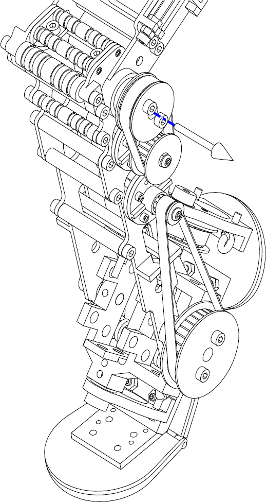
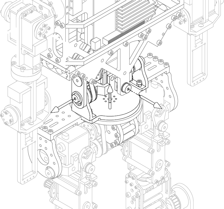
3.2 Trunk
While the human skeleton relies on the entire motion of the trunk section in a single flexible and ingenious structure – the spine – a humanoid design cannot afford mimicking such singular structure. Nevertheless, the usual approach is able to maintain most of the required movements of this section with a minimum of joints and related degrees of freedom. This conventional design is based on a rigid box representing the chest, which usually holds most of the control and power systems, connected to the lower section of the body, the lower limbs, through a three degrees of freedom joint.
To accomplish the required degrees of freedom, a three orthogonal rotary axes joint, following the design applied in the ankle and hip joints, is used in the connection between the hip section and the upper section of the chest assembly (Figure 5). Like in the solution used for the hip joint, the vertical axis of the trunk joint uses an axial bearing to support the vertical weight of the humanoid.
Lower trunk section joint
3.3 Upper limbs
The upper limb section includes the shoulder, the elbow and the wrist joints. Humanoid hand and related kinematic assembly is not included in this section, and disregarded from this study documentation, since several solutions can be considered, from a simple one dof claw to multi dof robotic finger assemblies able to accomplish most movements of the human hand.
The usual mechanical approach to represent the human shoulder simply disregards about 50% of its motion capability. In fact, this global joint is formed by three main individual joints: the glenohumeral joint, the acromioclavicular joint and the sternoclavicular joint, and the usual ball joint applied in the humanoid design is only able to represent the first one. This mechanical joint enables the flexion/extension, abduction/ adduction and internal/external rotations, and the combined movement of circumduction. Taking advantage of the other joints, the human shoulder is also able to perform depression/elevation and retraction/protraction movements, a set of degrees of freedom that is usually disregarded in humanoid designs without loss of the most important features of this critical joint. In the current design a three axes rotary assembly, similar to the one used in the hip joint, is used (Figure 6).
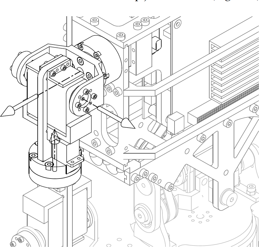
Shoulder joint assembly
While the human elbow provides two degrees of freedom: the flexion/extension of the forearm and the pronation/supination of the forearm (combined with the same effect provided at the wrist joint), the current design only provides the flexion/extension movement. The other degree of freedom only has final effect on the hand, and, for this reason, this degree of freedom is often moved to the wrist kinematics joint. Therefore, the elbow joint is simply represented by a hinge connection performing a single rotary degree of freedom.
The human wrist is a complex joint, gathering the movements allowed by the extrinsic hand section, which allow for the pronation/supination movements, and the intrinsic hand section, providing the palmar flexion and dorsiflexion and the radio/ulnar deviation movements.
This three axial joint requires the use of a combined joint similar to the one applied in the hip joint. Since this joint design is larger than the permissible volume space to accommodate the wrist joint, a simplified approach must be used: a dual axis design, neglecting the deviation movement, or even a single longitudinal rotary joint, where the remaining degrees of freedom is accomplished by the extrinsic hand section.
3.4 Neck joint section
Contrary to the human being, the main function of the humanoid head is to support the vision and auditory systems. Therefore, the degrees of freedom required for the neck joint must, merely, resemble the pan and tilt movements, a requirement that is easily accomplished by a dual rotary axis assembly.
4. Hybrid actuation
4.1 Actuation challenges
An increasing number of studies support the idea that the structure and mechanical characteristics of the robot body (i.e., morphology) play a crucial role in behaviour generation and control. The morphology determines the kinematics and dynamics of the robot, and thereby the possible repertoire of behaviours, as well as affects the control required for these behaviours. The relevance of this idea has become apparent with the seminal work of Tad McGeer [24] who built self-stabilizing passive mechanisms which could walk down a slope in the absence of control. Since then, many other robots have been developed demonstrating how well-designed morphologies can lead to reduction in control requirements and improved efficiency [25-27].
The current research challenge is to design innovative robotic systems that combine energetic efficiency with the ability to execute a variety of complex manoeuvres without complex computation. Central to the study is the need to work out principles of biological systems and transfer desirable properties to the robot design – both existing and novel solutions. From a mechanical design standpoint, several new technologies can contribute to an economical and versatile robot.
The most obvious, yet most challenging, approach is to develop muscle-like actuators (e.g., McKibben muscles). At present time, these kinds of actuators are becoming commercially available and robotic applications will soon test their suitability for walking [28]. Another promising actuation concept for walking robots is series-elastic actuators, a combination of a spring and a motor [29]. The series elasticity allows storing and releasing energy during one gait cycle. Hybrid parallel actuation is another powerful practice in machine design and control in order to achieve greater energy efficiency and, expectantly, better reactivity during transients or fast responses [30,31].
In line with this, the strategy proposed in this paper, following the authors' recent activity [6], is to exploit the strengths of active actuation (Hitec digital servo motors) in terms of versatility and the advantages of passive mechanisms. For this purpose, the legs account for a set of insertion points that allow the inclusion of different mechanisms like springs, elastic fibres and other basic mechanisms of energy conservation. Although these design features can improve energy efficiency, they tend to be ill-suited for theoretical control design. Further, there are few theoretical methods which serve to analyse the role of passive elements combined with active actuation for reduced power requirements. This fundamental gap justifies our intention to perform the research, from various perspectives, in order to better understand the relationship between structure, dynamics and control.
4.2 The knee passive actuator
Although elastic components are being incorporated into most of platform joints, the knee presents a particular interest since it is deeply involved in more demanding gaits or locomotion tasks. Indeed, the knee may be subjected to high torques when bending to large angles and also when high responses are needed. Figure 7 shows the simulation of the required torque on the motor of the knee during full cycles from 0° (vertical leg) down to 80° bent and reverse, performed in 5 and 2 seconds shown respectively in the middle and bottom plots of the figure. The light curve indicates the torque required by the motor when an elastic element is present and the dark curve without the elastic element. Slight variations occur for the faster cycle due to dynamics issues, but in both cases the effect of the passive actuator is clearly noticeable.

Torques on the motor of the knee for cycles of 5 and 2 seconds
Having to fight gravity is usually an apparent drawback in many humanoid robots, but that can be turned into an advantage if storing potential energy is possible. This can be done by the use of elastic energy storage elements. Helix springs may be a suitable solution, namely, because of their linear behaviour with the torsion angle, which is interesting for control and modelling purposes. However, helix springs may turn out to be mechanically hard to tune and even troublesome to attach to the links they are expected to bind.
The alternative in this project has been to use linear elastic rubber bands duly guided though the structure around the knee. Moreover, the system was conceived in a way that these elastic bands remain confined to a path and may be manually tuned by stretching them and imposing an adjustable initial force offset (Figure 8). Although the force may be considered proportional to the elongation of the elastic band, that elongation may not be linear with the knee angle, nor will be the resistant torque that develops against that bending. Figure 9 illustrates a concept that allows keeping the torque generated by the passive actuator in raised levels throughout the full span of the knee joint.

Detail of the fixation and anchor points for the elastic bands

Model of the deformation of the knee elastic band
The multi bending points provide a stepwise adjustment of force direction to yield a more sustainable torque. The resulting torque is therefore monotonic with the angle (Figure 10 and Figure 11) and consequently usable as an additive torque component that will ease the task of the motor that drives the knee.

Sequence of knee angles (

Plot of torque developed by the passive actuator on the knee (the vertical lines indicate where new bending points start operating)
Concerns for other joints have also been taken into account, and although not as dramatic as in the knee, the reductions in the maximal torques needed by the motors when using elastic elements are still impressive. The ankle charts can be seen in Figure 12.

Torque on one of the ankle's motors during the motion of bending the leg involving hip, knee and ankle joints
For an easier comparison, Table 1 summarizes some simulation results of using passive actuators along with the motors. The gains in maximal torque reduction are relevant. Concerning the result of torque demands (Table 1, Figure 7 and Figure 11) one observation is worth mentioning: indeed, the presence of elastic elements reduces the limit torque demands, but of course, in situations where almost no torque was required (to initiate motion, for example), now, with passive joints, a slight torque is needed to cancel out the elastic elements initial opposition. This implies that this initial power dispense, when the motors and their controllers are fully in their most efficient operating zone, is stored on the elastic that will return it back in the reverse motion.
Summary of torques (Nm) and reduction in maximum absolute torques (%) during a full cycle of bending and raising up a leg using three joints

5. Perception and control
The requirements of autonomous operation demand large amounts of sensorial information plus the fusion of all the perception involved. Much like the biological systems do, the abundance of sensors is perhaps the most promising line towards autonomy of humanoid robots. At the same time, the model of a single unitary control system that takes the decisions and controls the other functions of a system tends to give place to alternative solutions. In line with this, a central focus of our research is the design of multiple independent control systems rather than a single monolithic one. The next subsections describe the implementation details of the perceptual system and distributed computer architecture in the full-body humanoid robot (Figure 13).
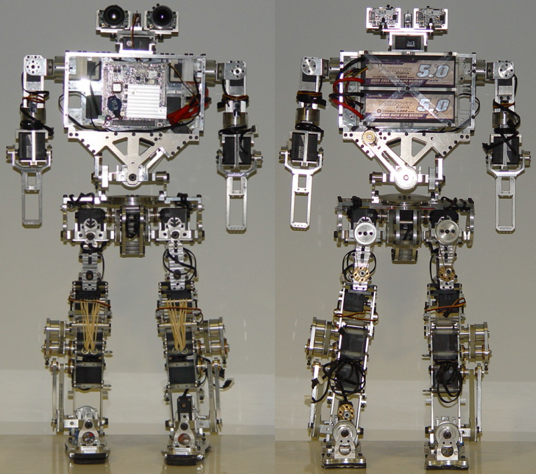
Front and back views of the full-body humanoid platform based on active and passive actuators
5.1 Perceptual system
The humanoid robot has a variety of sensory systems including proprioceptive and exteroceptive senses. Proprioception is needed for the internal controllers at the current state of the art. To mimic the human vestibular system, the last set of sensors incorporated on the platform accounts for inertial devices: gyroscopes and accelerometers will monitor the inertial status of several parts of the robot. Inertial sensors are used to provide the sense of equilibrium or balance (motion and orientation). For example, navigation in unstructured environments requires the information of the robot's spatial orientation with respect to the gravity vector, such that it becomes independent of the topology of the ground.
The uniqueness of the proposed development is that a network of these devices is being integrated along the overall robot's structure (not only the head and hip as is more common). This would be particularly relevant for a robot system that needs to adapt to complex and novel situations, and react to uncertainties in the environment. One of these devices has been developed in the authors' labs which includes an analogue 2 axes gyroscope (LPR503AL) and one 3 axes digital accelerometer (LIS331DLH) mounted on board with a Microchip PIC18LF2580-I/ML microcontroller and connecting to a CAN bus through a Texas Instruments SN65H233EP CAN bus transceiver.
Sensor modules (Figure 14) were made very small (21×12×7 mm) in order to install them in almost any place. The inertial modules are able to measure accelerations in 3 axes and angular velocities in 2 axes; future versions will use 3 axes digital gyroscopes that have been released by manufacturers.

Standalone inertial module (left) and in its configuration socket (right)
Exteroception concerns the measurement of the environment or its consequences on the platform itself. This accounts for vision-based perception and reaction forces. The vision system consists of two cameras that lie atop a 2-dof pan-tilt unit that comprises the “neck” of the robot (Figure 15). One camera captures a wide-angle view of the periphery and the other captures a narrow-angle view of the central area (i.e., foveal high resolution vision), supported by lens with focal lengths of 8 mm and 3.5 mm, respectively. The mechanical design of the neck assures that the combined range of motion of the neck and torso will provide the system with human-like motions. Vision abilities were added using the OpenCV library [32] installed on-board such that the system can perform visual detection and tracking of some objects moving in its neighbourhood.

FireflyMV cameras and lenses installed in the “head” pan-tilt unit
Previous authors' results with force sensors for body balance [5] ascertained the relevance of force sensors and in this platform new force sensors are installed at the corners of each foot to provide reliable data for the equilibrium-controlling system. More concretely, four 5-lbs (ca. 2.3 kg) load cells on each foot (see Figure 16) are used to sense the compression forces during the robot's walk, providing accurate measures of ground reaction forces and allowing real-time measurement of the centre of pressure. Figure 17 illustrates the raw signals derived from the force sensors during transient and steady-state responses upon several stimuli imposed on one foot. Force feedback introduced into the control system is essential to provide the level of compliance and adaptation necessary to improve the system's performance in real world environments.

The assembled articulated foot and the location of the force sensors (with a diameter of 9.6 mm)

Series of measurements of the force sensors in one foot upon load application
5.2 Distributed control architecture
The overall control architecture relies on a distributed network of different processor types operating at different levels in the hierarchy, ranging from small microcontrollers for joint-level control to a central processing unit for audio and visual processing. The proposed solution is based on a four level hierarchy of controllers: main control unit, master unit, slave units and servo's controller (see Figure 18). The main control unit consists of an embedded PC104-based controller with an Intel 1.6 GHz Atom processor running Linux. This processing unit serves as the top interface dealing with high level planning and reasoning, image acquisition and processing, remote interfacing for monitoring and possibly control, and communication by RS232 serial line with the master unit.
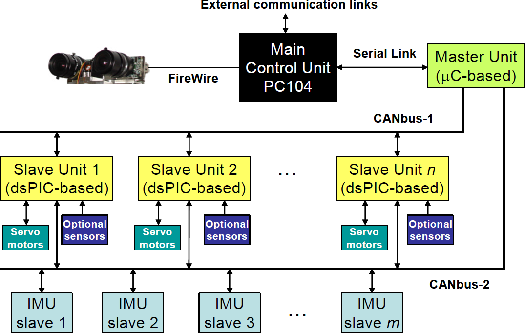
Main blocks of the distributed control architecture
The role of the master unit is to gather and maintain the system's status, as well as to establish the communication protocols between levels. The slave units, seeded all over the robot's structure, are responsible for actuator direct control, sensor reading (force, inertial, servo status) and immediate processing. A group of three joints has a custom-built board with a dsPIC33FJ128GP706 microcontroller (Microchip) which processes encoder and analogue/digital inputs, performs control calculations and drives the servos connected in parallel on the RS-232 communication bus. The slave units are connected by an ECAN bus which also includes the master unit. At the bottom of the hierarchy, each joint has a dedicated local motor controller provided by the servomotor.
The central processing unit is installed within the torso, jointly with the batteries that provide full energy autonomy to the system (Figure 19). The vision system is linked to the PC104-based central processing unit through a standard interfaces. Image processing and visual tracking algorithms are being executed in the main control unit that dispatches the motion directives to the appropriate slave control unit responsible for driving the pan-tilt actuators. A dual CAN bus separates control from high bandwidth sensorial data flow in order to improve the throughput of data and reliability of control. One of these buses will be dedicated to high bandwidth flow of sensorial data, namely inertial, force or even others to come in the future. For example, inertial modules are installed in this CAN bus as slave inertial measurement units (IMU). The other CAN bus is dedicated to the real-time control of the system such that all directives circulate on it. This ability is also central in order to exploit the possibility of advanced processing systems such as learned-based, where the global knowledge of data generated and processed locally may serve to supervise and monitor learning procedures.

View of the central processing unit and the pack of batteries housed within the torso
6. Conclusions and future perspectives
This paper presented the mechatronic design of a new small-size humanoid platform for research on bipedal locomotion. The goal of our work was to provide a reliable and highly integrated humanoid platform that allows the implementation and tests of various theoretical studies with potential application in real-world scenarios. Here, we addressed the mechanical design, the hybrid actuation system and the different subsystems of the robot, including the perceptual skills and the implemented hierarchical control architecture. On-board full processing and autonomy is now possible in what concerns control, perception and vision capabilities based on a distributed architecture in which independent and self-contained tasks may allow a standalone operation. In what concerns the hybrid actuation, the main result is that the incorporation of the passive element reduces enormously the torque extreme requirements, as well as saving and recovering energy. Besides power saving, the proposed approach increases motor efficiency by allowing them to operate far from their limits and obtaining better dynamic responses.
The new humanoid platform is nearly ready to exploit and numerous research lines, such as distributed perception, distributed control, learning-based operation and the role of passive actuators in hybrid control and actuation. First, pursuing a hybrid actuation system depends upon the assertion that an additional research effort is required once these design features are proven to be ill-suited for theoretical control design. This fundamental gap justifies a research effort in order to better understand the relationship between structure, dynamics and control.
Likewise, learning has become a powerful tool that uncovered a variety of solutions to classical problems in robotics. On-going research is focused on learning of behaviours where the robot incrementally learns based on successful execution of a task. Having this in mind, a set of computational tools are being developed such that an operator can interactively and gradually control the individual joints, provide functional guidance and corrections, while recording all the sensorial data. This information will allow the robot to extract correlations among sensorimotor events, to learn by itself the force-control laws that govern the execution of a given task, along with the knowledge of how to select, chain and combine behaviours. These problems are simply the beginning of a rich source of novel methods, computational developments and innovative engineering solutions.
Footnotes
7. Acknowledgments
This work was partially funded by Feder through the Operational Program Competitiveness Factors – Compete and by National Funds through FCT – Foundation for Science and Technology in the context of the project FCOMP-01-0124-FEDER-022682 (FCT reference PEst-C/EEI/UI0127/2011)