
Abstract
A new normalized coupling synchronization (NCS) method is proposed to solve the problem of synchronizing the speeds of all wheels in a multi-axis independent driving system without mechanical transmission connection. The NCS method integrates normalizing and coupling techniques by emulating mechanical line shaft. All wheels' speeds are normalized, and thus can be synchronized whether the wheel's revolution speeds are the same or different. Then, all of the normalized wheel speeds are coupled in order to eliminate speed synchronization errors between any pair of axes. Therefore, the new algorithm is able to achieve global speed synchronization. It is applicable to multi-axis driving vehicles either driving in straight line or making a turn. The conducted computational simulation shows that the proposed method gets better result in reducing speed synchronization errors in both cases of same and different wheel speeds compared to some classic speed sync methods in the literature. To further validate the effectiveness and applicability of the NCS method, it is also applied to a four-wheel-driving and four-wheel-steering vehicle for comparison tests. The onboard tests indicate that the proposed method achieves a fast convergence of speed error.
1. Introduction
Multi-axis independent driving system became popular in robotics and vehicles nowadays. It improves the maneuverability of the vehicle. In addition, the traditional mechanical transmission has been replaced, which makes the design of vehicle even more flexible. Various specialized platforms equipped with two or more independent motor powered driving wheels, such as the lunar rover and the mars explorer [1], and robotic vehicle platforms in agricultural application, i.e., weed control, automatic spraying and harvesting [2–6].
A vehicle in 2D space is usually considered to have three DOFs (two translational and one rotational), while the multi-axis driving system gives redundant controllable DOFs. The independent motors make the robot flexible with different freedom of steerability and mobility [7]. Take a 4WD-4WS vehicle in 2D space for example, there are 4 DOFs of wheel speed and another 4 DOFs of steering angle. The 8 controllable DOFs are usually constrained by the kinematic model of the vehicle. However, in practice, any independent motorized wheel might be interfered, especially when the vehicle travels on soft, rough terrain. If either axis slows down due to the torque variation on that axis, the other wheels are demanded to slow down. Therefore, the synchronized motion control of multi–axis becomes a challenge when following variable command trajectory or under process loading [8]. This work addresses the issue of multi-axis speed synchronization. And we will illustrate the idea of our method and demonstrate its effectiveness via a 4WD-4WS vehicle.
2. Review of existing methods for speed synchronization
A critical analysis of literature survey revealed that a multi-axis speed synchronization algorithm for vehicle motion control should address more than three motors, eliminate the synchronization error, embrace time variable speed ratio between motors, and possess robust dynamic performance and real time capability. There are some studies on synchronization for multi-motor applications [9], which can be referenced for our motion control. The methods could be classified into three categories: basic methods, cross-coupling methods, and electronic virtual line shafting (EVLS) methods.
The two basic methods: the average speed method and the Master-Slave method, have been studied. The average speed method simply makes all motors work close to the average speed [10]. The Master-Slave method set the speed of the master motor as the reference for the slaves. The disturbances on the master will be conducted to the slaves, but the reverse is impossible. The master-slave method has asymmetric response and low dynamic synchronization performance. Studies showed that these basic methods are simple to implement, but poorer in speed and angle synchronization performance than others [9, 11].
Since Koren originally proposed the cross-coupling technique for CNC machine [12], similar ideas were further developed [13]. The cross-coupling method was used to improve the accuracy of trajectory tracking for a differential robot [14]. It has been widely used, and provides good speed and position synchronization performance. The original cross-coupling method limits itself for two motors only. To overcome this limitation, it has been extended to handle multi-axis systems. Extended methods include the relative cross-coupling method [15], the adjacent method [16–18], and the ring method [10]. Adjacent cross coupling and ring cross coupling methods use the speed of adjacent motor as feedback compensation. This design results in the unequal response of all motors due to the conduction delay of the speed change. The cross-coupling method has been generalized to the cross coupling control which can handle various process of multi-axis control [19, 20]. Similarly, a neuro-controller using the cross coupling method improved the synchronization performance of a nonlinear system [21]. The cross-coupling family is simple, expandable and easy to implementation with good synchronization results. But it is not fit for multi-axis systems in different speed synchronization situation.
The electronic virtual line shafting (EVLS) emulates the physical line shaft connected to sectional mechanical drives [22, 23]. Electrically synchronized motors system is able to replace the mechanical transmission. The virtual line-shaft generates the master reference for speed synchronization. Each virtual in-shaft only follows the master reference with independent gear ratio. And the torque of each axis feeds back to the main shaft. This method rejects load disturbances applied to any motor, and offers speed synchronization in both case of same speed and different speed cases. EVLS is much more complicated than any other methods, and leads to slow transient response [9, 11].
This study proposes a new multi-axis speed synchronization algorithm that is especially suitable for 4WD-4WS vehicles. The rest of the paper is organized as follows. Sections 2 discusses the kinematics of four wheel driver and four wheel steer vehicles. The theory of our proposed speed synchronization algorithm is described in Section 3. Tests of the new method both via simulation and on a 4WD-4WS vehicle are given in Section 4, followed by results and discussions presented in Section 5. Finally, Section 6 conclude the paper.
3. Wheel speed relationship in a 4WD-4WS vehicle
A 4WD-4WS vehicle in 2D space usually defined to be a three Degrees of Freedom system with two translational and one rotational. For the local motion control, the relative speed state of the vehicle
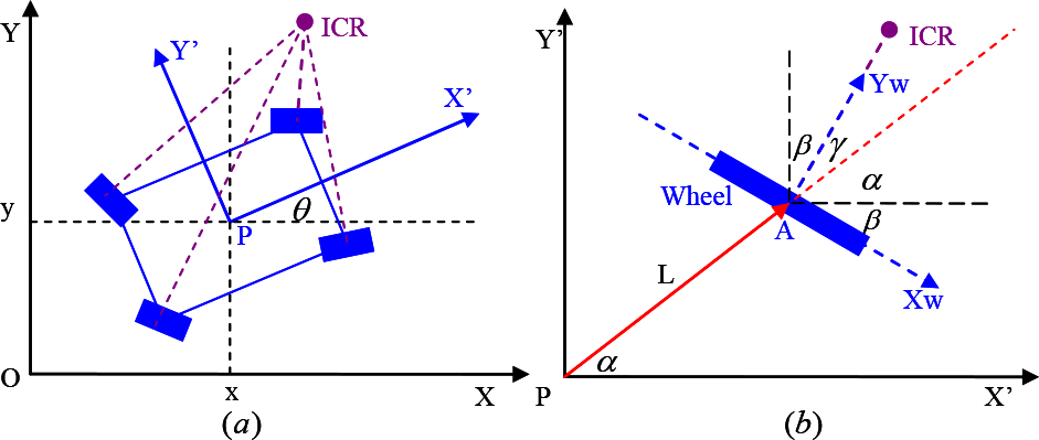
Two dimensional Coordinates: (a) robot coordinates, (b) wheel coordinates.

A 4WD-4WS vehicle that has four driving motors and four steering actuators is redundant. Controlling the 3-DOF relative speed state of the vehicle will change the state of eight controllable DOFs due to the constraint of the vehicle kinematic model. All of the wheels are assumed to be doing pure rolling at any instant. And all of the spin axes should intersect at one point, which is called the Instantaneous Center of Rotation (ICR) (Fig. 1). The speed of each wheel and steering can be determined as per Eq. (2) and Eq. (3). We assume that the steering of the each wheel is accurate. Only the wheel speed is discussed in this paper.


where:

φ is the angular velocity vector of wheels. And r is the radius matrix of wheels. So the translation velocity vector of wheels along the wheel panel could be stated v = r φ.
In practice, the speed of any wheel may not follow the kinematic constraint due to the load variation or slippage. In figure 2, wheel-4 is hampered by an obstacle. It then becomes slower than the other wheels when the vehicle is going straight (Fig. 2(a)), or slower than its desired speed when the vehicle is turning (Fig. 2(b)). If some wheel's speed is unable to follow the kinematic model, it could lead to deformation of the vehicle chassis, as shown in figure 3. A possible solution that can be easily thought of is to increase the output of the hampered wheel, and slow down the unhampered ones. However, the kinematic model is impossible to conduct the speed variation to others. Hence, a speed synchronization controller is required to maintain the ideal kinematic model.

Wheel hampered (a) going Straight (b)Turning

Chassis deformation caused by out of speed sync
4. Normalized Coupling Synchronization Method
Typically, synchronization of two or more moving parts in a machine is achieved by gear drive or belt and pulley drive. The Normalized Coupling Synchronization method (NCS) derives its basic principle from mechanical transmission.
First of all, the running synchronous wheels are considered to be connected to a virtual line-shafting source wheel with different virtual transmission ratios (Fig. 4).

Wheels (top row) connected to a virtual line shaft (bottom row)
If the desired angular velocity of the virtual line shaft is

where ηi (t) is transmission ratio of the virtual line shaft to the ith wheel at time t. and ηi ≠ 0.
From Eq. (4), the relationship between the desired speeds of all the wheels can be written as:
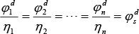
Similarly, if the actual speed of the ith wheel i is φi, and the actual speed of the virtual line shaft is φs. Then the relationship between them can be written as:

Combining Eq. (5) and Eq. (6), the speed of each wheel is normalized by its desired speed. The normalized speed ratios can be expressed as:

Define the normalized speed of the ith wheel as:
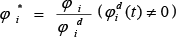
The normalized speeds are comparable at any time, especially when the speeds are unequal, or the desired speed is set to any value by the kinematic model.
If all of the motors are synchronized (global speed synchronization), then the relative normalized speed of any motor pair in a multi-axis system will be zero, and can be expressed as:

Similarly, the normalized speed synchronization error between any two motors can be expressed as:

If for any pair of wheels i and j, εij = 0 is achieved, then global speed synchronization of motors would be accomplished.
The NCS algorithm uses the coupling technique to establish the communication between wheels. The normalized speed errors between any two wheels are computed. The coupler sums the normalized speed error for all wheels in the rule as follows. The total normalized speed error of the ith wheel is:

The Fig. 5 shows the control scheme of the NCS method for a multi-axis system. The implementation of the NCS method is the NCS controller in dashed box. The NCS controller derives its desired speed command from the kinematic model, and samples the actual speed response from individual wheel module. In order to eliminate normalized speed synchronization error, NCS outputs the reference speed commands in the following control rule:

Schematic of the NCS method for multi-axis driving systems
The wheel modules are the part of the native multi-axis system. They are independent and separated from the speed synchronization controller. Thus the brief introduction is stated for better understanding. There is a close loop feedback control system in each independent wheel module, which includes controller, motor and transmission, as shown in Fig. 6. Each wheel module requires its own speed reference and processing load as inputs. And it outputs the actual speed with minimum speed tracking error.

wheel module diagram
5. Materials and Methods
In this section, we proceed to validate the NCS algorithm. A couple of classic methods are selected for comparison in identical simulation environment. The NCS algorithm is also implemented into a 4WD-4WS vehicle control system to demonstrate its applicability in practice.
5.1 Simulation of the proposed and selected sync algorithms
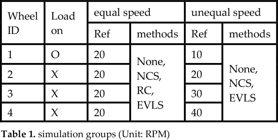
In order to verify that the new proposed NCS algorithm is able to handle speed synchronization for a multi-axis driving system of vehicle (whether the vehicle is driving in straight line, or turning), NCS applied on a four-axis independent wheels system was simulated in Matlab/Simulink (The Mathworks Inc). Two generalized cases were analyzed: a) all four wheels were desired to spin at the same speed (20RPM); and b) four wheels were running in different speed (In this work, we took 10, 20, 30 and 40RPM respectively for demonstration). During the total simulation of 20 seconds, a torque load of 100Nm was applied to wheel-1 at the 5th sec, and released at the 10th sec in both cases.
The Relative Coupling (RC) method and Electric Virtual Line Shaft (EVLS) method were selected for comparison in the identical simulation environment described above. A simulation with no synchronization is also conducted. The simulations are grouped in Table 1. The RC method is not presented in case (b) since it is not applicable for different speed synchronization.
simulation groups (Unit: RPM)
5.2 Testing of the proposed and selected algorithms on a developed 4WD-4WS vehicle
In order to further demonstrate the applicability and effectiveness of our method, the NCS was tested on a 4WD-4WS bioenergy close proximity sensing vehicle. It is an electricity powered vehicle equipped with 4 independent DC motor driving wheels (Fig. 7). The vehicle weights around 1500 Kg with 3m × 3m × 3m in dimension. The height could be adjusted up to 4m for tall crops.

Overview of the bioenergy close proximity sensing vehicle
We conducted the vehicle test for both cases of same and different speed copying from the simulation. The vehicle disengaged its clutch, so that the speeds of the four wheels could be set flexibly. The NCS method was embedded into the vehicle real time control system. The high-level controller of the vehicle generated the reference speed command. And the load was applied manually to wheel-1 in the same fashion as in the simulation.
6. Results and Discussions
6.1 Results of Simulation case (a): Same speed
In the simulation case (a), as the load acted on wheel-1 of the four-axis driving system without speed sync, the speed of wheel-1 changed as much as 9rpm (Fig. 8(a)), whereas the speed of the other wheels stayed unchanged. And the speed sync errors between wheel-1 and the others were 9rpm (Fig. 8(b)). The speed sync error between wheel-i and wheel-j is defined as: Eij = φi – φj. The speed of wheel-1 converged to its initial value due to the efforts of the wheel module controller.

No synchronization for same speed simulation (a) speed chart (b) speed sync error chart
The RC method, the ELSV algorithm, and the NCS method were compared in case (a) as well (Figs. 9–11). All the three methods took effect when the disturbance acted on wheel-1. All the wheels adjusted their speed in order to reduce the sync speed error. When the load was applied to wheel-1, it slowed down. And the other wheels followed. Opposite trend was observed when the load was released from wheel-1. The results of RC and NCS were noticeable, while the EVLS was not quite obvious.

RC for same speed simulation (a) speed chart (b) speed sync error chart

EVLS for same speed simulation (a) speed chart (b) speed sync error chart

NCS for same speed simulation (a) speed chart (b) speed sync error chart
EVLS was effective for speed synchronization. The speed of wheel-1 varied about 11rpm. And the others changed about 3rpm. The speed sync error reduced a bit to 8rpm. However, it was still greater than that of RC and NCS.
RC and NCS achieved better synchronization performance. Both of them reduced the speed of wheel-1 about 3.7rpm as the load engaged. Meanwhile, the speeds of the other wheels decreased about 1.7rpm. Similarly, when the load was released from wheel-1, it speeded up and the other three wheels followed. It resulted in about a speed sync error of 2rpm, which was more than 75% decrease compared to no synchronization.
NCS could be considered as an RC module with a normalizer for processing unequal speeds. In this case, the coupler parameters of NCS were as same as RC. So the results derived from both RC and NCS were quite close. And they were considered to be the best in the same speed synchronization comparison.
Due to the lack of the capability for processing unequal speeds, the RC method was absent in case (b).
6.2 Results of Simulation case (b): Different speed
In the different speed simulation group, four wheels were desired to rotate at 10, 20, 30, and 40 rpm, respectively. The load is applied on wheel-1 at the 5th sec and released at the 10th sec as same as in case (a).
Similar to case (a), wheel-1 ran at 10rpm decelerated by 9rpm when the load acted on. And the other wheels gave no response to the disturbance (Fig. 12 (a)). The normalized speed sync error was used as an index to demonstrate the synchronization performance for different speed (Fig. 12 (b)). The normalized speed sync error between wheel-i and wheel-j is defined as:

NONE for different speed simulation (a) speed chart (b) normalized speed sync error chart
Fig. 13(a) shows the results of EVLS. Once the load got applied on wheel-1, EVLS slowed down the speeds of wheel-2 to 4 unequally. Wheel-4 decreased about 3rpm, which was greater than wheel-3 and wheel-2 did. The normalized speed errors of E12, E13 and E14 are shown in Fig. 13(b). E12=E13=E14 indicates that EVLS has obtained identical responses of speed difference between wheel-1 and the other wheels, but the peak instantaneous error was as great as 0.9.
EVLS for different speed simulation (a) speed chart (b) normalized speed sync error chart
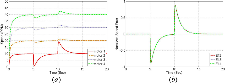
The results of NCS for different speed simulation are presented in Fig. 14. When the load applied to wheel-1, the speed reduced about 4rpm compared to 9rpm of the EVLS method. The other three wheels followed with greater speed reduction than EVLS. The shape of normalized speed errors of NCS was similar to EVLS (Fig. 14(b)). And the error magnitude was about 0.2 compared to 0.9 of EVLS.

NCS for different speed simulation (a) speed chart (b) normalized speed sync error chart
Both selected methods were able to reduce the speed synchronization error in different speed group. Obviously, NCS shows a better synchronization performance than EVLS. That is because NCS is less complicated than EVLS. NCS is capable of fast transient response to disturbances. It reduced the speed change magnitude of the hampered wheel, and increased that of the unhampered ones quickly. So the sync error was reduced significantly. And the sync error could converge to zero faster than EVLS.
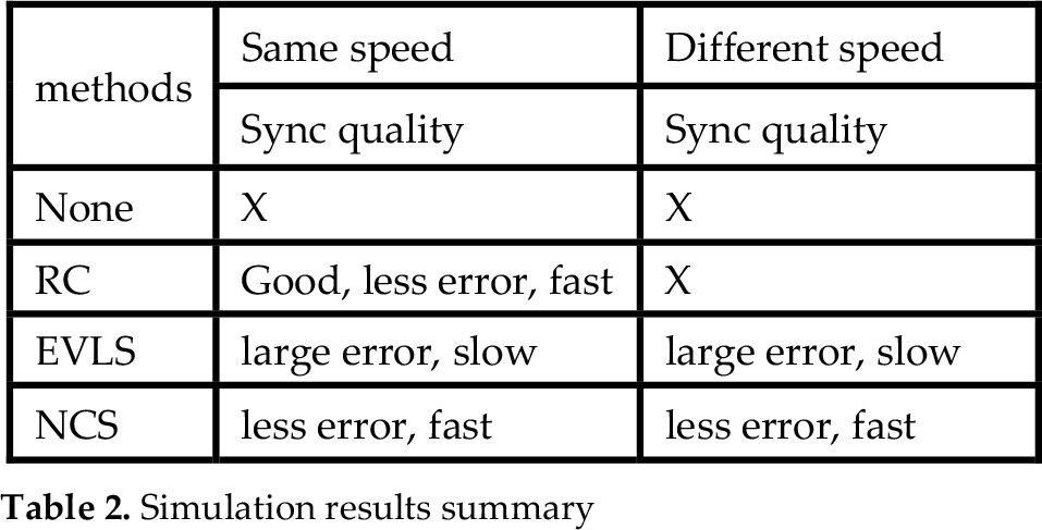
The results of the simulation have been summarized in table 2. The new proposed NCS method is as good as the RC method in same speed group. And it presents an advantage over RC for the ability of synchronizing multi-axis in different speed. Although EVLS is suitable for all speed conditions as well, NCS has a quicker transient response to the disturbances, a faster convergence of speed sync error and a small magnitude of speed sync error than EVLS.
Simulation results summary
6.3 Results of vehicle test
The NCS method was embedded to the real-time control system of a 4WD-4WS bioenergy close proximity sensing vehicle to validate the applicability. The vehicle was configured to drive all wheels on demand to further improve simulation results in practice. The speed synchronization tests for both same and different speed were conducted. And similar cases as simulation were carried out for NCS. Figs. 15 and 16 shows the results for same speed test without synchronization and with NCS. Fig. 17 shows the speed response of no synchronization algorithm for different speed test and Fig. 18 displays the results of the NCS algorithm.

No sync for same speed vehicle test (a) speed chart (b) normalized speed sync error chart

NCS for same speed vehicle test (a) speed chart (b) normalized speed sync error chart

No sync for different speed vehicle test (a) speed chart (b) normalized speed sync error chart
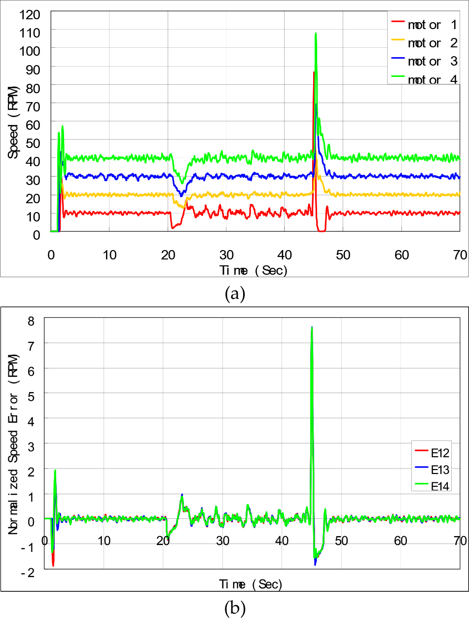
NCS for different speed vehicle test (a) speed chart (b) normalized speed sync error chart
The curves are quite similar to the results of corresponding simulation cases. NCS took effects on speed sync. It made the other wheels follow the speed of the wheel-1, onto which the disturbance load was applied. The simulation results have been verified in practice.
When the load was applied, there was a low ebb on the speed curve without sync control (Fig. 15 (a) and Fig. 17 (a)). However, NCS recovered the speed error to zero quickly by comparing the charts of speed (Fig. 16 (a) and Fig. 18 (a)). And the peak value of speed sync error reduced slightly compared to the result of simulation. That is because the transient response of NCS in real-time systems is slower than the system in simulation.
Rotate vibration occurred on wheel-1 as the load acted on it in practice. NCS helps to restrain the vibration when syncing the speed. However, the other wheels were infected with vibration somehow.
The overshoots of the speed sync error occurred (Fig. 16(a)) due to the coupling of NCS and the independent motor controller. The gains of both controllers took effect simultaneously.
7. Conclusions
A new normalized coupling synchronization method was proposed. It is designed to fit for multi-axis independent driving systems, and take place of mechanical transmission. It could handle the speed synchronization problem of vehicle with multiple controllable DOFs, and give much more maneuverability.
Compared with some simple methods (e.g., Relative coupling algorithm), the new NCS method enjoys a similar low level of complexity and achieves a good performance as same as others. The simulation results show NCS can achieve a significant reduction of speed sync error (up to 75%). The vehicle tests indicate that global speed synchronization could be achieved rapidly. NCS establishes itself out from others in synchronizing unequal speeds.
Although EVLS is also able to handle multi-axis system, NCS is much less complex, which results in fast transient responses. The simulation results indicate that the performance of NCS is faster and better. Meanwhile, the simple NCS algorithm could be easily coded in embedded systems for real-time control, and combined with vehicle motion control systems.
It is not difficult see from NCS's design idea, described in section 3, the normalizer and coupler can accept more than three speed inputs. NCS is extensible and suitable for speed synchronization of independent multi-wheel driving systems. It is applicable for more generalized situations, e.g., 6WD-6WS vehicles.
The test results of NCS on a 4WD-4WS vehicle are in good accordance with simulation. It demonstrates the applicability and effectiveness of the new algorithm. Yet, there are some flaws when the NCS was applied to a real time control system. The peak value of the speed sync error is reduced slightly, but converges fast. Due to the coupling of NCS and the real time controller of wheel module, the gains of both controllers are accumulated, which makes the system tend to overshot. The noise and vibration could be amplified. Thus, it is of interest for further research that the speed synchronization algorithm pay more attention to anti-noise, and improving the real time control quality of faster convergence, less overshoot, and more robust.
Footnotes
8. Acknowledgments
This work has been funded by the Energy Biosciences Institute through the program titled ‘Engineering solutions for biomass feedstock production’.