
Abstract
The multi-axle emergency rescue vehicle has dangerous driving conditions, high body height, and large weight, and the coupling of each subsystem of the chassis is more complicated. In order to solve the coordination problem between the vehicle suspension system and the steering system, the vehicle can drive more smoothly on uneven road surfaces and improve the riding comfort of passengers. A sliding mode dual robust coupled collaborative control strategy is proposed to address the impact of the multi-axis steering system and active suspension system on driving smoothness and handling stability of emergency rescue vehicles. The active suspension system and multi-axle steering system are synergistically controlled. Firstly, an active suspension sliding mode variable structure controller is designed to improve vehicle ride comfort. Secondly, A new dual robust controller is proposed to realize the handling stability of the vehicle’s all-wheel steering system. Thirdly, the coupling cooperative controller of the active suspension system and all-wheel steering system is designed and simulated under different working conditions. The experimental results show that the root-mean-square values of body roll angle, body roll angle acceleration, and yaw angle acceleration with cooperative control are reduced by 26.58%, 30.54%, and 21.92% respectively; moreover, the lateral acceleration and vertical acceleration of the vehicle body are effectively reduced. The use of cooperative control effectively improves the ride comfort and handling stability of the vehicle.
Introduction
The vehicle’s suspension and steering systems are important parts of the vehicle chassis system. Multi-axis emergency rescue vehicle has dangerous driving conditions, high body and heavy load, and the coupling of its chassis subsystems is extremely complicated.1–3 Numerous scholars have conducted extensive independent control studies on active suspension systems and steering systems,4–6 but the comprehensive performance of the system is not a simple superposition of the control results of the two subsystems.7–9 The collaborative control of active suspension and steering system coupling can coordinate the advantages and functions of each subsystem, thereby further improving the comprehensive driving performance of the vehicle.10–13
Some scholars have done corresponding research on the cooperative control of the active suspension system and steering system. Akhmetov proposed a control strategy that integrated vehicle braking, the front and rear steering system, and suspension with different actuators to improve the safety of heavy vehicles. 14 Jo developed the estimators of vehicle roll angle and sideslip angle based on a simplified roll dynamic model and parameter adaptive method. 15 Chokor et al. designed the integrated controller of active suspension and front-wheel steering system and optimized the weight coefficients of each sub-controller to coordinate each subsystem and improve the comprehensive driving performance of the vehicle. 16 Harada proposed the relevant rules of linear quadratic regulator (LQR) controller, optimized the weight coefficients of suspension system and steering system, and improved the handling stability of vehicles. 17 Dahmani et al. used Takagi-Sugeno fuzzy model to estimate and predict the state of the centre of mass yaw rate and yaw rate, and proposed a state feedback controller to prevent rollover. 18
At present, the research on active suspension and steering systems is mostly limited to the research on single subsystem of active suspension and steering, and the research on all-wheel steering of vehicles is mostly focused on two-axle vehicles,19–21 as well as the coupling and cooperative control of steering system and suspension system of multi-axle vehicles. The model established by most scholars is too linear and idealized, which is quite different from the actual model,22,23 and the expected effect cannot be achieved in concrete implementation.
In this paper, an 11-degree-of-freedom coupling dynamic model is established considering the coupling between the active suspension and the steering system of multi-axis emergency rescue vehicles, and a sliding mode variable structure controller for active suspension and a dual robust controller for multi-axis steering is designed. The active suspension and the multi-axis steering system are cooperatively controlled to optimize the vehicle body vertical acceleration, the body roll angle and the yaw acceleration of the suspended vehicles, and the effectiveness of the proposed cooperative control strategy is verified by experiments.
Coupling dynamic model of suspension system and steering system
The suspension system serves as a vital link between the vehicle body and the wheels, while the active suspension system actively controls the actuator to counteract road impacts based on road and vehicle conditions. When steering at high speeds in a multi-axle vehicle, it minimizes body sway, thereby reducing the likelihood of collisions. During medium-speed steering, lane changes are smoother, alleviating driver fatigue. At low speeds, it decreases the turning radius to enhance vehicle manoeuvrability and flexibility. The suspension system and steering system are two crucial interconnected subsystems within the vehicle chassis. Their coupling relationship, constraints, and coordination collectively influence ride comfort, handling stability and manoeuvrability of the vehicle. Considering these existing phenomena and addressing current issues at hand, this paper aims to conduct research in the following areas:
The 11-degree freedom model of the steering and suspension system coupling is shown in Figures 1 and 2. The model includes the lateral motion of the three-axle vehicle along the Y axis, the roll, pitch, yaw motion of the sprung mass, the vertical motion of the centre of mass and the vertical motion of six unsprung masses.
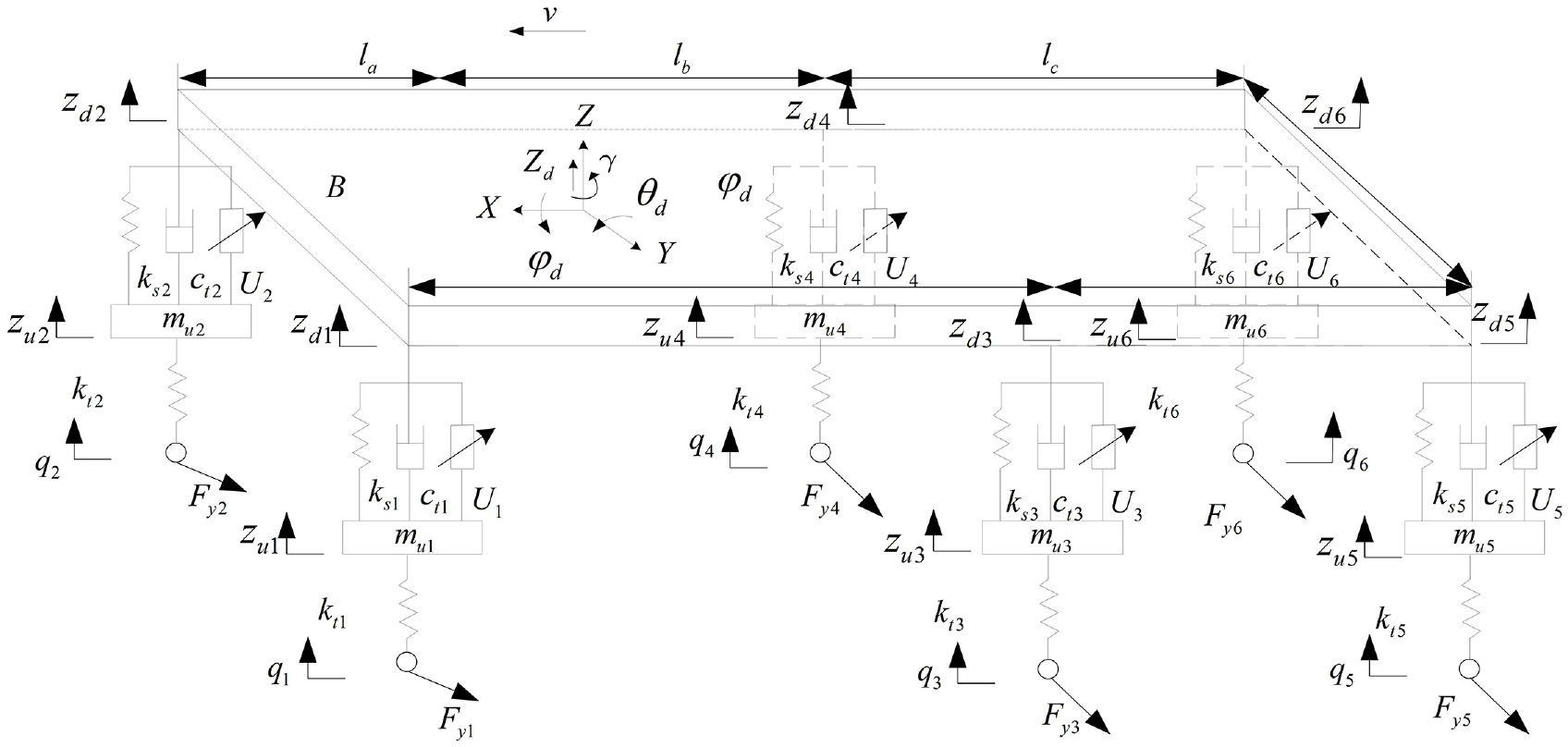
Front view of the model.

Top view and front view of the model.
The coupling dynamic model of the suspension system and steering system is shown in Figure 1. The model includes the roll, pitch, and yaw movements of sprung mass around the X-axis, Y-axis and Z-axis, the lateral movement of the vehicle along the Y-axis, the vertical movement of the centre of mass, and the vertical movements of six unsprung masses.
The variables in the model are shown in Table 1.
Model variables (

As shown in Table 1, m s and m ui represent the sprung mass and each unsprung mass, respectively. Z d , z di and z ui denote the vertical displacement of body mass centre, displacement at each suspension fulcrum and each unsprung weight displacement, respectively. q i and B are input of each road surface and the wheel track, respectively. l a , l b and l c represent the distance between the centroid and the front axis, the centroid and the central axis, the centroid and rear axle, respectively. φ d , θ d and γ represent the pitch angle, roll angle and yaw angle of the vehicle body, respectively. αi, β and δ j (j=f,m,r) represent the angle between each wheel, sideslip angle and wheel angle, respectively. I x , I y and I z denote the body roll moment of inertia, the body pitch moment of inertia and the rotational inertia of yaw around the Z-axis, respectively. k si , c ti and k ti represent the equivalent stiffness coefficient of each suspension, the equivalent damping coefficient of tire and the stiffness coefficient of each tire, respectively. U i and F yi denote the active output force of each suspension and the lateral force on each tire, respectively. v and h s are the speed of vehicle and the distance from roll centre to centre of mass, respectively.
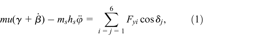
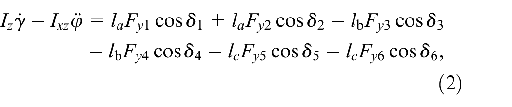
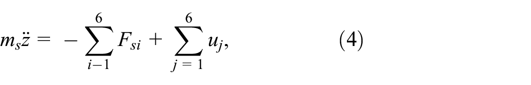
According to Newton’s second law and Figure 1, the vehicle dynamics equation is expressed as:


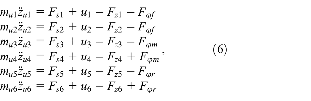
where

where
The dynamic model is transformed into a spatial state equation, and the system variable X is taken as:

If only the linear part of the suspension is considered, the output force of each suspension can be expressed as:

Combined with (7)–(9), the nonlinear sub-module is regarded as the external input of the state equation, and the external input vector is:

where,
The control quantity of the coupling system of the suspension and steering system is taken as:

The output variables of the coupling system are:

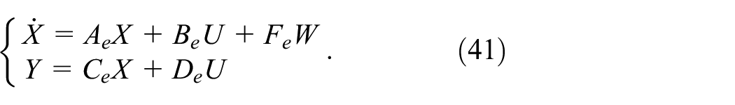
The nonlinear model of coupling system with 11-degree of freedom is:

where
Sliding mode variable structure control of active suspension system
The sliding mode controller is designed for the active suspension system of the emergency rescue vehicle, and the uncertainty and interference exist in the control process to optimize the ride comfort of the vehicle.
Establishing a generalized error dynamic model:

Let the output force of sliding mode controller be equivalent vertical control force

The generalized error dynamics equation is:

Design of sliding surface
The generalized error equation and sliding mode switching surface equation of active suspension are established as follows:

where E is the vector error of the sliding mode controller, U is the equivalent control quantity, S is the switching function, and C is the sliding mode parameter coefficient matrix.
There is a nonsingular linear transformation matrix T, which satisfies

where
The original system (17) can be changed into a quadratic state:


When the system is on the sliding surface, substitute

The analysis shows that

Let

where
Design of sliding mode control rate
Adopt constant velocity approach rate:

In order to ensure the accessibility and existence conditions of sliding mode system,
The design process of sliding mode control rate must consider the external disturbance of road random input, namely:

When

we get

The corresponding equivalent sliding mode control force is:

When the motion point of the system enters the switching surface

After replacing

The corresponding equivalent sliding mode control force at
According to logical reasoning, after

where

The equivalent sliding mode control force on

The sliding mode variable structure control principle of active suspension is as follows: Firstly, the road excitation signals
Double-Robust controller for multi-axis steering
In order to improve the handling stability of the three-axis emergency rescue vehicle, a dual robust controller for multi-axis all-wheel steering is established based on the theory of zero centroid slip angle and the method of tracking the ideal yaw rate. 24
The ideal reference model when the vehicle is driving at high speed can be expressed as:

where
The ideal reference model for steering at low speed can be expressed as:

Design of H∞ robust controller for sideslip angle of centre of mass
The difference between the measured true value and the ideal sideslip angle is expressed as:

Introducing augmented state variables:

For linear time-invariant systems:

The status expression is as follows:
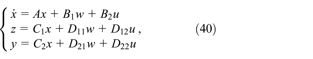
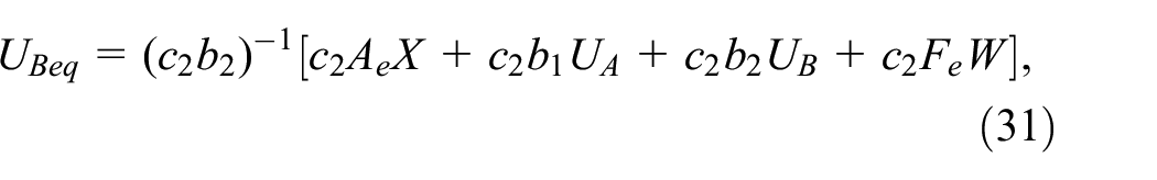
Convert to the form of robust tracking standard:
Combined with formula (40), the state space description of linear time-invariant system P(s) can be obtained, and the β-suboptimal H∞ controller of sideslip angle can be obtained.
Design of H∞ control based on yaw rate
The difference between the measured yaw rate and the ideal value is expressed as:

Introducing augmented state variables:

Similarly, the state space description of linear time-invariant system P(s) can be obtained by combining formula (40), and the
Design of dual H∞ robust controller for multi-axis steering
The front axle steering signal

Cooperative control of active suspension and multi-axis steering system
Cooperative control strategy
The suspension system and steering system jointly affect the ride comfort and handling stability of the vehicle during driving. The cooperative control strategy of active suspension system and multi-axis steering system is shown in Figure 3.

Collaborative control strategy.
As shown in Figure 3, ULSS stands for the upper layer cooperative controller, WC stands for weight coefficient, DRC-SS stands for the dual robust controller for steering system, ARSMC-AS stands for the anti roll sliding mode controller for active suspension, SMVSC-AS stands for the sliding mode variable structure controller for active suspension, ASS stands for the active suspension system, M-ASS stands for the multi-axis steering system, ERVS stands for the emergency rescue vehicle system.
The coordinated control strategy designed in this paper includes execution layer, control layer and coordination layer. The executive layer includes multi-axis steering system and active suspension system, the control layer is dual robust controller of steering system and sliding mode controller of active suspension, and the control layer is composed of upper coordinated controller.
The upper-level collaborative controller adjusts the weight coefficients K1, K2 and K3 output by the controllers in the control layer in real time according to the vehicle speed v x (km/h), steering angle |δ f |(rad) and threshold value δ0 (rad) when the vehicle is driving in a straight line or turning direction, so as to achieve collaboration with the sub-controllers. The control rules are as follows:
If (v x > 0 and δ f < δ0), then K3 = 0
Then the sliding mode controller for ride comfort of the active suspension works to reduce the vertical displacement, pitch angle, roll angle, vertical acceleration, pitch angle acceleration and roll angle acceleration at the centre of mass of the vehicle body as the control objectives, and good results can be obtained only by relying on the active suspension ride comfort controller, that is, K3 = 0, K1 = 1 and K2 do not affect the control effect at this time.
If (v x > 0 and δ f ≥ δ0), then K3 = 1
At this point, the vehicle is affected by the lateral torque, and the vehicle body will have a large roll angle, and the roll angle will increase with the increase of the front wheel angle df. At this time, the main task should be to improve the handling stability of the vehicle and reduce the roll angle of the vehicle body. The dual sliding mode control for active suspension and the dual robust controller for steering work at the same time, and the weight coefficient K1 is reduced, while the weight coefficient K2 is increased, and K3 = 1.
Due to the constant change of vehicle motion state, there is a high requirement for the real-time performance of the weight coefficient, and it is impossible to establish an accurate mathematical relationship between the observation and the weight coefficient, so the weight coefficients K1, and K2 are obtained through fuzzy reasoning.
The inputs of the upper layer cooperative controller are the absolute value
Then the input actuating force U i of the active suspension system is:

Simulation analysis
Taking the established nonlinear coupling model as the control object, the simulation analysis is carried out under the working conditions of step steering and double line shifting, and the effect of coupling cooperative control of the active suspension system and steering system is compared with that of individual control.
Working condition 1: step steering working condition
Set the speed of 36 km/h and the front wheel angle of 5 on the C-class pavement step condition, and the response curves of the vehicle under independent control and cooperative control are shown in Figures 4–9.

Sideslip angle.
Yaw rate.
Roll angle acceleration.

Roll angle.

Lateral acceleration.
Vehicle body vertical acceleration.
As can be seen from Figures 4–9 and Table 2, under the step steering condition, the response peak of the coordinated control is lower and the fluctuation range is smaller than that of the individual control. The root-mean-square (RMS) of the sideslip angle, roll angle, and roll angle acceleration are reduced by 88.75%, 36.75%, and 30.49%, respectively, and the RMS of yaw rate, lateral acceleration and vehicle body vertical acceleration are reduced by 1.44%, 17.21%, and 52.85%, respectively. The above results show that the cooperative control can actively suppress the attitude vibration and steering performance of the vehicle better than the single control under the step steering condition.
RMS of related indicators under step steering condition.

Working condition 2: double-shift line condition
Set the C-class road surface with a speed of 36 km/h and a front wheel angle of 5, and the response curves of the vehicle under independent control and coordinated control are shown in Figures 10–15.
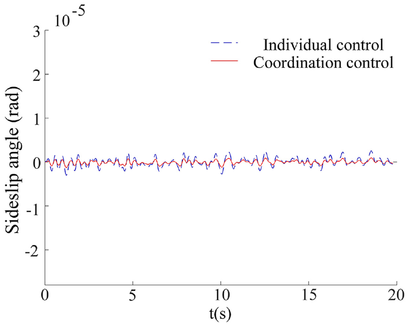
Sideslip angle.

Yaw rate.

Roll angle.
Roll angle acceleration.

Lateral acceleration.
Vehicle body vertical acceleration.
As can be seen from Figures 10–15 and Table 3, under the double-shift line condition, the lateral acceleration fluctuation range of the coordinated control is smaller than that of the individual control. Under the coordinated control, the RMS of the sideslip angle, yaw rate, and lateral acceleration decreased by 13.92%, 18.3%, and 6.52%, respectively, and the RMS of the roll angle, roll angle acceleration, and vehicle body vertical acceleration are reduced by 36.17%, 31.91%, and 32.39%, respectively. The above results show that under the double-shift line condition, cooperative control can obtain better handling stability and ride comfort than individual control.
RMS of relevant indicators under double-shift line conditions.

Experiments
In order to verify the effectiveness of the cooperative control strategy proposed in this paper and ensure the accuracy of the test, several steering tests are carried out, and 30 s effective test data are selected to compare the RMS of each index of individual control and cooperative control.
Experiment with main components and related parameters
The main components include: angle sensor, electro-hydraulic servo valve, proportional control valve, hydraulic pump, servo amplifier, pressure sensor, and inertial measurement unit. The road steering of the whole vehicle is shown in Figure 16. Information such as vertical displacement, pitch angle acceleration, and roll angle acceleration of the vehicle is obtained by the inertial measurement unit; The sliding mode controller of active suspension solves the ideal actuating force of active suspension; Combined with the weight coefficient K1 of sliding mode controller of active suspension and the weight coefficient K2 of steering robust controller, six ideal actuating forces of active suspension are determined. Finally, each control variable acts on the electro-hydraulic servo valve through D/A conversion, so that the test vehicle can get the ideal active suspension as the driving force and the ideal rotation angle of the middle and rear axles. Relevant parameters are shown in Table 4.

Inertial measurement unit and vehicle road steering.
Main parameters of the vehicle.

Left turn test under random pavement conditions
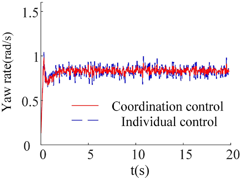
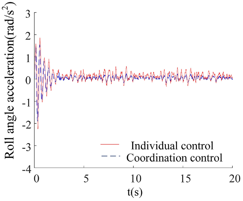
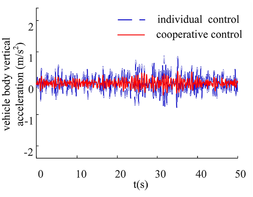
Let the test vehicle run on C-class road at a speed of 30 km/h, and turn left into the curve after 40 m, as shown in Figures 17 to 22, and the root mean square values of related indicators are shown in Table 5 respectively.

Lateral acceleration.
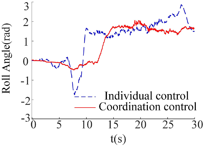
Roll angle.
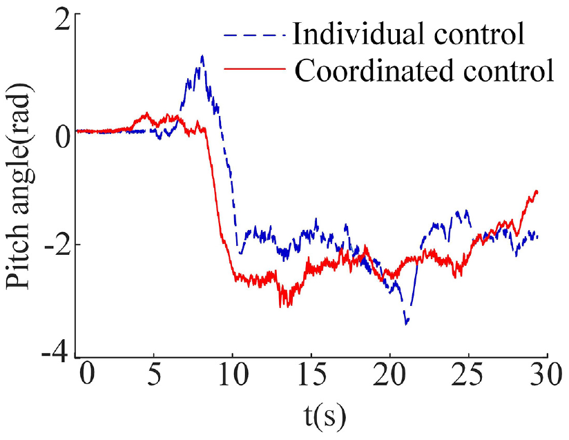
Pitch angle.

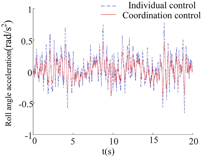
Roll angle acceleration.
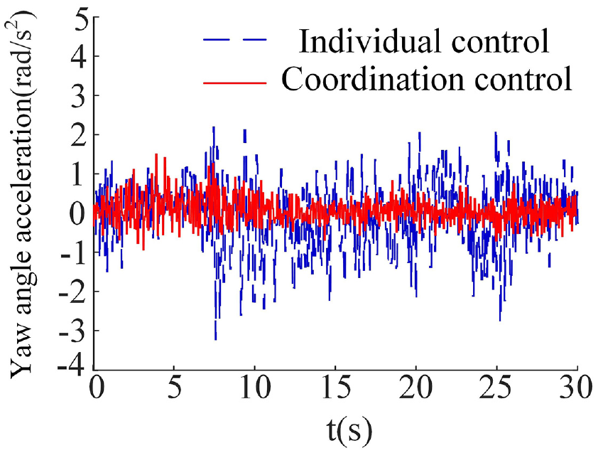
Yaw angle acceleration.

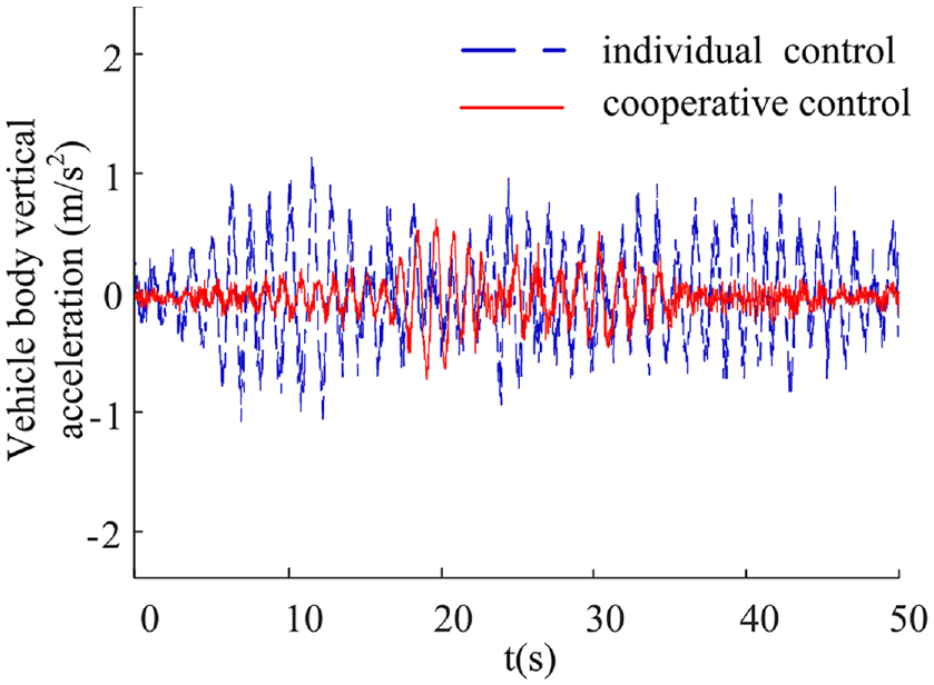
Vehicle body vertical acceleration.
RMS of test results of related indicators.

As shown in Figures 17–22 and Table 5, compared with the individual control, the RMS of vehicle body roll angle, roll angle acceleration, and vehicle body vertical acceleration under the cooperative control are reduced by 26.58%, 30.54%, and 29.74, and the RMS of vehicle body pitch angle, yaw angle acceleration, and lateral acceleration are reduced by 26.15%, 21.92%, and 15.08%, respectively. Through the above analysis, compared with individual control, coordinated control can effectively reduce the load transfer during steering and the vertical vibration of the vehicle body, the steering stability of the three-axis emergency rescue vehicle under coordinated control has been well improved.
Conclusion
This article focuses on the special chassis and suspension system of emergency rescue vehicles. In order to improve the ride comfort and handling stability of the vehicle, a coordinated control study was conducted on the active suspension system and multi-axle steering system. Based on different dynamic models and multiple controllers, as well as road testing of the entire vehicle using a test vehicle. The following conclusions were drawn:
(a) Based on the vehicle dynamics model and the ideal model of all-wheel steering, this paper puts forward a cooperative control strategy of coupling active suspension and steering systems. The dual robust controller and active suspension sliding mode controller of all-wheel steering system are designed to improve vehicle handling stability and ride comfort.
(b) This article establishes a nonlinear dynamic model of the coupling between the active suspension system and the steering system, and uses a hierarchical control strategy to synergistically control the active suspension ride comfort controller, active suspension handling stability controller, and multi-axle steering system controller.
(c) The test results show that compared with the individual control, the RMS of vehicle roll angle, roll angle acceleration, and yaw angle acceleration under the cooperative control are reduced by 26.58%, 30.54%, and 21.92%, respectively, and the vertical acceleration and lateral acceleration of the vehicle are effectively reduced. The proposed coordinated control strategy of active suspension and steering systems can effectively improve the ride comfort and handling stability of emergency rescue vehicles.
Due to the limitation of test conditions, the research work of this paper needs to be further improved: When studying the active suspension system in this paper, a random road surface is taken as the system input. If the road grade is taken as the input of the active suspension, the control effect of the active suspension control system will be significantly improved. In this paper, the control strategy proposed in the study of the cooperative control of the two systems is only verified under typical working conditions. Still, the actual driving conditions of the vehicle are much more complex and need to be further verified under more complex working conditions.
Footnotes
Handling Editor: Sharmili Pandian
Declaration of conflicting interests
The author(s) declared no potential conflicts of interest with respect to the research, authorship, and/or publication of this article.
Funding
The author(s) disclosed receipt of the following financial support for the research, authorship, and/or publication of this article: This work was supported by the Joint Fund for Regional Innovation and Development of the National Natural Science Foundation of China (U20A20332) and the National Natural Science Foundation (52175063).