
Abstract
Stereo vision has been studied for decades as a fundamental problem in the field of computer vision. In recent years, computer vision and image processing with a large field of view, especially using omnidirectional vision and panoramic images, has been receiving increasing attention. An important problem for stereo vision is calibration. Although various kinds of calibration methods for omnidirectional cameras are proposed, most of them are limited to calibrate catadioptric cameras or fish-eye cameras and cannot be applied directly to multi-camera systems. In this work, we propose an easy calibration method with closed-form initialization and iterative optimization for omnidirectional multi-camera systems. The method only requires image pairs of the 2D target plane in a few different views. A method based on the spherical camera model is also proposed for rectifying omnidirectional stereo pairs. Using real data captured by Ladybug3, we carry out some experiments, including stereo calibration, rectification and 3D reconstruction. Statistical analyses and comparisons of the experimental results are also presented. As the experimental results show, the calibration results are precise and the effect of rectification is promising.
1. Introduction
Stereo vision has been studied as a fundamental problem in computer vision for decades. By stereo matching, depth information can be obtained, which can be used in many applications such as autonomous navigation, obstacle detection, 3D reconstruction, virtual reality, object recognition and surveillance. For stereo matching, calibration and rectification are considered to be important pre-steps. By calibrating a stereo system, extrinsic parameters of the stereo system can be obtained to calculate the depth information. Calibration is also a must when rectifying stereo image pairs. A pair of images is thought to be rectified when its epipolar lines coincide [1]. One of the most important advantages of rectification is that the search for correspondences is done along the rows or the columns of the rectified images [2].
In recent years, computer vision and image processing with a large field of view (FOV), especially using omnidirectional vision and panoramic images, have been receiving increasing attention for navigation and surveillance applications [3]. Especially, the omnidirectional multi-camera system (OMS) has some more attractive advantages over other types of omnidirectional cameras. Firstly, an OMS supplies higher resolution. Additionally, it also provides uniform resolution for any direction of view. Stereo systems composed of OMSs also have these advantages. Consequently, the research into the calibration and rectification methods for this kind of systems is meaningful and necessary.
Many algorithms for calibration and rectification have been proposed in omnidirectional applications. However, the existing approaches suffer the following defects: (1) Most of them are limited to calibrate and rectify catadioptric cameras with parabolic, hyperbolic, elliptical or spherical mirror and fisheye cameras. It is not convenient to apply them directly to OMSs (Ladybug3 [4], e.g.). (2) Some calibration methods need special facilities and scenes which are not simple to make and commonly available. (3) Some of the rectification methods are not scanline rectification methods, thus losing the important advantage of making the search for correspondences faster and simpler. (4) Part of the rectification methods produce heavily distorted images.
To solve these issues we propose a method for calibration and rectification in this paper which is proved to be well suited to OMSs. This calibration method is based on a spherical model without intrinsic parameters. We first deduce the projective properties of a group of equidistant parallel lines on the checkerboard. Based on these properties, the closed-form solutions of the extrinsic parameters are obtained. With the closed-form solutions as initial guesses, the calibration method produces a refined result by optimizing the object functions we propose. The rectification method we propose is a scanline method. It reprojects the stereo image pair onto a public unit sphere, on which the corresponding epipolar lines are projected onto the same longitude line. For a certain stereo system, the rectification process can be parameterized as a look-up table, which is easy to implement on a field-programmable gate array (FPGA) or a graphics processing unit (GPU).
There are two main contributions in this paper. Firstly, we propose a calibration method with iterative optimization and closed-form initialization which is well suited to OMSs. Secondly, we design a rectification algorithm [5] to project the corresponding epipolar lines onto the same longitude line on a unit sphere. This algorithm is a scanline algorithm and is convenient for hardware implementation with highly parallel processing. The algorithm also avoids the heavy distortion which is common in existing methods.
The remainder of this paper is organized as follows: In Section 2 we introduce the related work. Section 3 discusses the proposed calibration method for an OMS. In Section 4, we describe the process of stereo rectification in detail. Lastly we present our experimental results for real images and draw the conclusions.
2. Related Work
2.1 Calibration Methods for Omnidirectional Cameras
Researchers have proposed many calibration methods for single viewpoint omnidirectional cameras and most of these methods can be classified into the following three general categories [6]: the planar-grid-based methods, the line-based methods, and the non-prior-knowledge methods.
2.1.1 Planar-grid-based Calibration Methods
As methods using planar grids [7] are wildly adopted for their simplicity of use and accurate results in the calibration of perspective cameras, researchers naturally tend to develop similar approaches for omnidirectional cameras. D. Scaramuzza et al. [8] propose a method to calibrate single viewpoint omnidirectional cameras based on the assumption that the image projection function can be described by a Taylor series expansion whose coefficients are estimated by solving a two-step least squares linear minimization problem. However C. Mei and P. Rives point out that the user has to select each point of the calibration grid independently when calibrating for the use of the polynomial approximation of the projection function. They propose an improved method in [9] by introducing a slightly modified sphere model of Geyer [10] and Barreto [11]. This method is simple without the need to know the mirror parameters. Gasparini et al. recover the intrinsic parameters of the central catadioptric cameras from the image of the absolute conic (IAC) in [12]. Deng et al. [13] use the bounding ellipse and the field of view to initialize the intrinsic parameters and then obtain the extrinsic parameters by computing the homography using a direct linear transformation (DLT) algorithm with data normalization. Ikeda, S. et al. [14] propose a calibration method for an OMS. They compute the intrinsic and extrinsic parameters using a target plane and a laser total station. Generally speaking, the main advantages of this kind of method are the high precision, and that the target plane used is simple to make and commonly available.
2.1.2 Line-based Calibration Methods
Line-based calibration methods such as [15]-[19] usually need only one view to carry out the calibration process. These approaches estimate the intrinsic parameters of the catadioptric system by means of computing the image of the absolute conic. The main advantage of line-based calibration methods is that no special pattern is needed because lines are easily found in the natural scene. However, the accuracy of this kind of method is usually lower than that of the planar-grid-based calibration methods.
2.1.3 Non-prior-knowledge Calibration Methods
Self-calibration methods, such as [20]-[22], use only point correspondences in multiple views, without needing any prior knowledge about the scene. However, they are less satisfying for 3D reconstruction and motion estimation due to limited precision.
Compared with previous methods, our calibration method is also based on a sphere model, but the model is simplified without intrinsic parameters. Additionally, our method is a combination of the planar-grid-based method and the line-based method. The line-based algorithm is used in the initialization stage. As we mentioned above, this algorithm enables us to get relatively accurate initial calibration results conveniently from only one view. In the iterative optimization stage, we design the objective function using the planar-grid-based technique which produces higher precision.
2.2 Rectification Methods for Omnidirectional Cameras
Considering that former researchers have proposed a lot of effective methods on matching perspective stereo pairs, people try to rectify omnidirectional stereo pairs and then transform omnidirectional stereo problems into traditional stereo problems. Many methods are proposed to rectify different kinds of omnidirectional stereo image pairs. C. Geyer et al. propose a method to rectify stereo image pairs of parabolic catadioptric cameras [23]. However, this method is limited to parabolic catadioptric stereo systems. Also, the method produces heavily distorted images. S. Abraham et al. propose an algorithm for fish-eye-stereo calibration and epipolar rectification [3]. Although it avoids heavy distortion and over expansion near the epipoles, the method is not a scanline rectification method, thus losing the important advantage of making computing stereo correspondences simpler. Researchers also exploit the rectification under different geometry frameworks. For example, Gonzalez-Barbosa et al. [24] rectify omnidirectional images on the rectangular grid, while Takiguchi et al. [25] reproject omnidirectional images onto cylinders. F. Kangni et al. [26] rectify the image pairs using the cubic projection model.
Although all the approaches mentioned above exhibit good behaviour in rectification, they still suffer at least one of the following defects: (1) some of the rectification methods are not scanline rectification methods, thus losing the important advantage of making the search for correspondences faster and simpler; (2) some of them produce heavily distorted images; (3) some are not easy for hardware implementation.
3. Stereo Calibration of OMSs
3.1 The Ladybug3 Omnidirectional Camera System
The high resolution Ladybug3 spherical digital video camera system () has six 2 MP cameras that enable the system to collect video from more than 80% of the full 360° sphere, and an IEEE-1394b (FireWire) interface with locking screw connection that allows JPEG-compressed 12MP resolution images to be streamed to disk at 15fps. The Ladybug3 camera system can output not only six normal images, but also an omnidirectional image either in DOME mode or Mercator mode. The Mercator mode panoramic images provided by the Ladybug3 are created using a spherical coordinate system. The projection model is as follows. The image axes u and v map to the two spherical angles θ and φ respectively in the following formulations:
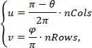
where nCols × nRows is the size of the panoramic images, θ and φ defined in are computed as follows:

where (x, y, z) is a point in the camera head coordinate frame. Substitute Eq. 2 into Eq. 1, we get

where d = √x2 + y2 + z2.

Ladybug3 Omnidirectional System.

The projection model of Ladybug3.

The model plane is on the

Two sets of the great circles intersect at
This simple spherical angle projection has been chosen because it maps nicely to a 2D image display.
3.2 Independent Extrinsic Calibration
In this part, we will calibrate the rotation and the translation between the target plane and the camera in each view. The final results are solved with the Levenberg-Marquardt algorithm. Consequently, we will discuss the initial guess of the rotation and the translation first. And then, a complete procedure of estimating the best result will be given.
3.2.1 Initialization of Extrinsic Parameters in Each View
In our algorithm of initialization, we will first estimate the rotation matrix. Then the translation can be obtained based on the estimated rotation matrix.
Let
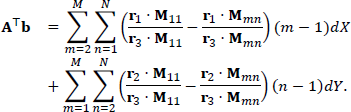
Without loss of generality, we assume the model plane is on the x – y plane of the world coordinate system, as shown in, that is z w = 0. Let dX and dY denote the size of each square in the grid in Xw and Yw.
There are two sets of parallel lines on the checkerboard. Each line is perpendicular to the lines in the other set. When projected to the viewing sphere in, each line forms a great circle. As shown in, the great circles corresponding to the parallel lines from the same set intersect at two antipodal junctions (

Once we obtain the initial guess of the rotation matrix

Let dmn be the distance from

As the normal of the checkerboard is

Substitute Eq. 7 into Eq. 8, we get

We can rewrite it as

Substitute Eq. 10 into Eq. 7, we get

Let

Since the model plane is on the x – y plane of the world coordinate system and the point

Substitute Eq. 13 and Eq. 11 into Eq. 12, we have

According to, we can rewrite

From Eq. 14 and Eq. 15, we can construct two equations with a single point

For a checkerboard with M × N grid corners, we can construct (M – 1)N + M(N – 1) equations. All these equations form an overdetermined system with the form

where

and
3.2.2 Optimization of Extrinsic Parameters
Next, we will find the final results of the extrinsic parameters by applying the iterative optimization.
By extracting the grid corners in the images, we are given M × N points on the target plane. Assume that the image points are corrupted by independent and identically distributed noise. The maximum likelihood estimate of
where
Noticing that

Therefore, the normal of the target plane in the camera frame is given by:

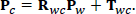
3.3 Stereo System Calibration
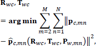
We treat the stereo system as a strictly rigid system. Consequently, the calibration of this stereo system is to estimate the best transform between Camera h and Camera l. We propose a two-step calibration process. In step I, we decouple the problem of finding the best transform into estimating a rotation part and a translation part independently. In step II, we use the results in step I as the initial guess to optimize the cost function to refine the results. We have two choices of the cost function: the first one is chosen to be the distance from the 3D points of the grid corners in one camera to the corresponding target plane observed from the other camera; the second one is the Euclidean distance between the 3D correspondences observed in the two cameras.
For each posture of the target plane, we can calculate its rotation

and

where mis the number of stereo image pairs.
Then the estimate of the translation has a closed form solution as follows:

and

where
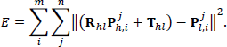
In Step II, what we do is minimizing a cost function which stands for the error of
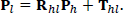
Let

This means the distance from the 3D points of the grid corners in one camera to the corresponding target plane observed from the other camera should be zero if the extrinsic parameters
Another objective function is given more naturally in that it requires the Euclidean distance between the 3D points observed in the two cameras should be a minimum. The objective function is given as follows:
These two nonlinear optimization problems given in Eq. 29 and Eq. 30 can be solved by using the Levenberg-Marquadrt algorithm.
When solving the optimization problem using the first object function Eq. 29, we should notice that at least three views of the target plane which are nonparallel to each other are required to fully constrain the optimization problem. Since the solution of the system has 6 degrees of freedom (DOF) and each view can constrain 2 DOF, we need at least three views of the target plane. If the number of views is smaller than three, the solution obtained will not converge to the actual value.
4. Stereo Rectification Method
4.1 Geometric Framework
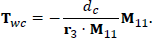
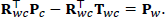
Firstly, let's make some notations clear. Let Oh be the origin of the camera head reference frame h and Ol be the the origin of the camera head reference frame l. From the calibration data, we are able to derive the extrinsic parameters
Imagining that if we set up a rectification reference frame r whose z is along the baseline

All the points belonging to a certain epipolar plane are projected on the same line in the
In order to transform the coordinates from the reference frames h and l to the reference frame r, we have to decide

where
By substituting Eq. 32 and
From Eq. 33, we can derive

Obviously, once
Next, let's estimate

Substitute the coordinates of point

and the following constraint because

where I is an identity matrix. Eq. 36 and Eq. 37 form a group of indeterminate equations because the reference frame r can rotate around the axis z. For simplicity, we let r11 = 0 and show the corresponding analytic solutions as follows:

4.2 Rectification with Interpolation
Without loss of generality, we do not limit the projection model of the camera as long as the correspondences in the same row or column of the rectified images have constant zenithal angles if we take frame r as the reference for the spherical coordinate system. Here we take Mercator projection as the model and the relation between every pixel in the rectified images and the corresponding points on the sphere is given by Eq. 3.
Supposing that we want to derive the intensity of a pixel with the coordinate [i, j] in the rectified image, we first calculate its coordinates on the sphere

where p = m – 〈m〉 and q = n – 〈n〉, 〈• 〉 means rounding the element to the nearest integer towards minus infinity.
5. Experimental Results
The experiments are conducted on the platform of Ladybug3. Camera h and Camera l are installed with a baseline of about 37cm in the vertical direction. The resolution of the images captured by Ladybug3 can reach up to 5,400×2,700, which enables us to obtain a more precise calibration result. We carry out the experiments in two different scenes and show one of them for rectification and the other for 3D reconstruction.
5.1 Calibration
The method we proposed requires image pairs of the 2D target plane in a few different views. In this experiment, a target plane with a printed chessboard pattern is used. The target plane has 11 × 11 squares and the side of each square is 30mm. We get nine pairs of stereo images in total. In this experiment, we have done some statistical analysis on the calibration results. The rotation part of the calibration result is expressed in Euler angles (α, β, γ), and the translation part is expressed as a 3D vector (tx, ty, tz). In Table 1, we have shown the variation of the calibration results obtained from different numbers of images. The results shown in Table 1 are obtained by using Eq. 29 and Eq. 30. As the method using Eq. 29 requires at least three views of the target plane to give the right results, we set the ‘Num of images’ to increase from 3. We can see that the σ of the results given by Eq. 29 is generally larger than that produced by Eq. 30.
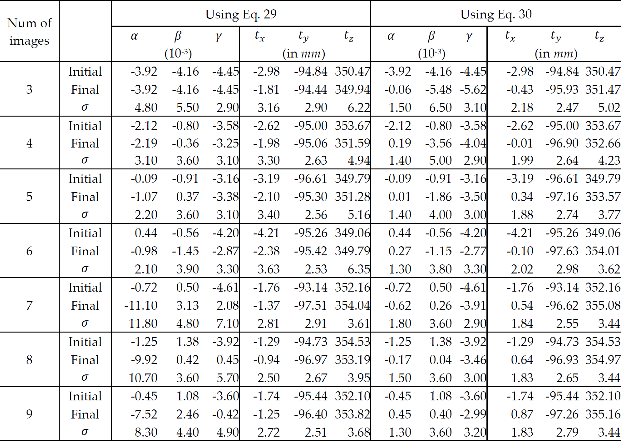
In order to investigate the stability of the proposed methods, we have applied the two methods using Eq. 29 and Eq. 30 to all combinations of eight images from the available nine images. We use Exc. i to denote the combination with the ith image excluded. For example, Exc. 9 means the results come from the images of 1–8. All the results are shown in Table 2 and Table 3. We find that the deviations from both methods are quite small and it implies that both the proposed algorithms can be considered stable. Since the deviation of the results given by Eq. 29 is still slightly larger, this may indicate that the method using Eq. 30 is probably more robust.
Variation of the calibration results among all continuous 8 images using Eq. 29

Variation of the calibration results among all continuous 8 images using Eq. 30

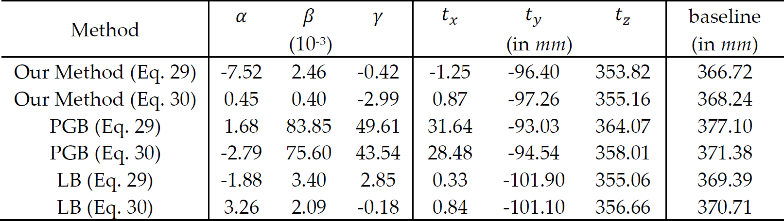
We also compare the results from our method with other previous methods in Table 4. The existing algorithms or toolboxes are mostly designed specifically for dioptric or catadioptric cameras. Their contributions are mainly concerned with the estimation of the parameters of the projection model. The Ladybug3 system is not only an OMS without intrinsic parameters, but also with a different projection model. In order to apply the previous methods on the Ladybug3 system, we partly modify the methods, including removing the calculation of the intrinsic parameters and replacing the projection model. We compare two kinds of the existing methods with ours In Table 4. One is the planar-grid-based (PGB) method similar to [9], in Table 4. The other is the line-based (LB) method similar to [15]. The PGB and LB methods in Table 4 are followed by Eq. 29 or Eq. 30, which means Eq. 29 or Eq. 30 is chosen as the object function for the optimization of the stereo calibration.
Comparison of our calibration method with other previous ones
5.2 Stereo Rectification
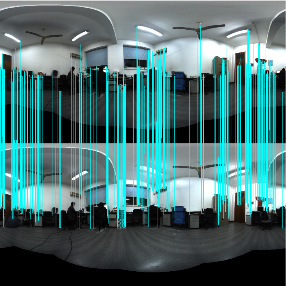
Figure 6 is the original image pair captured by Ladybug3 in this experiment and Figure 7 shows the rectified images from our rectification method. We line up the correspondences which are found and matched using Scale-invariant feature transform (SIFT). According to Figure 7, we can see that the correspondences fall on the same columns in the rectified pair. In order to make the results clear, we make some comparisons between the picture blocks from an unrectified stereo pair and a rectified stereo pair.

Original image pair
Rectified image pair
Figure 8(a) presents the details from the unrectified image pair. It is clearly shown that the stereo correspondences are not on the same line. Consequently, the performance of stereo matching will be poor.
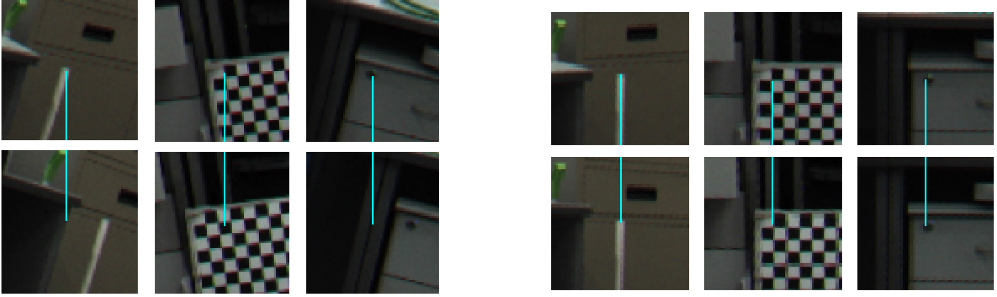
Comparison between the picture blocks from an unrectified stereo pair and a rectified stereo pair. Picture blocks in the first row are from Camera
Experiment of 3D reconstruction.
Figure 8(b) presents the details from the rectified image pair. We can observe that the stereo correspondences fall on the same line after rectification. Comparing the details from Figure 8(a) and Figure 8(b), we can conclude that our method of calibration and rectification is effective.
We also record the time required to perform the rectification on a PC platform. The average time to rectify a 2700×1350 grey image is 2.66 seconds, while the average time for a coloured image of the same size is 9.29 seconds. All experiments were carried out on a server with an Intel Xeon X5560 CPU (2.80GHz), 12G RAM, running Matlab 2009 64bit. For an FPGA with an 80MHz system clock, it theoretically takes 228ms to rectify a 2700×1350 grey image pair by taking advantage of the parallel computing and the pipeline framework. For a coloured image of the same size, the time increases to 0.68s.
5.3 3D reconstruction
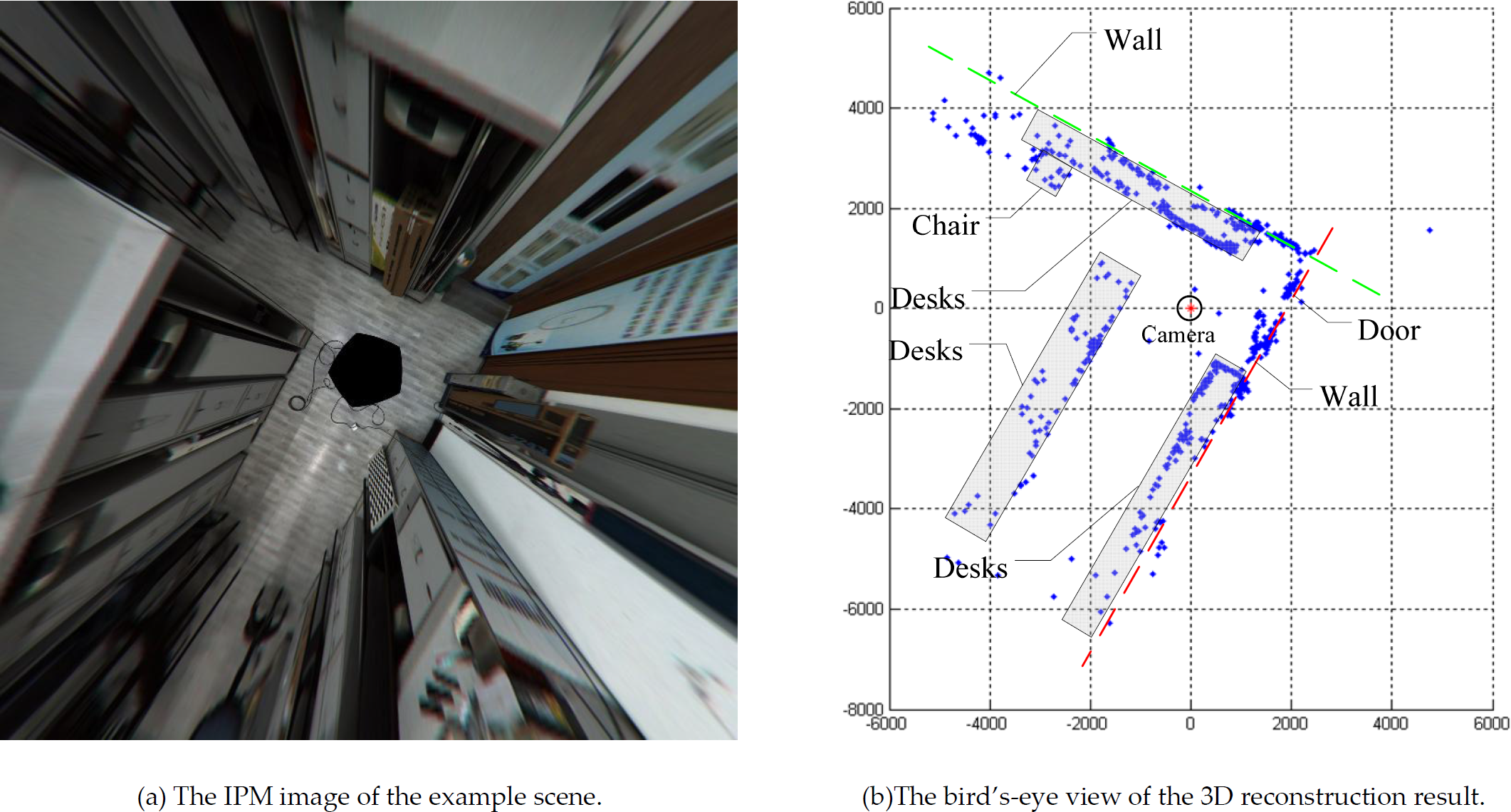
In this experiment, we have also obtained the 3D reconstruction results of the example scene by calculating the intersection of two rays using equation [29]. The virtual bird's-eye view (by IPM) is shown in (a). The reconstruction results can be seen in (b). As the experiments are carried out in the corner of the room, we should observe two walls perpendicular to each other in the bird's-eye view of the reconstruction result. (b) strongly agrees with this inference. In the point cloud, the two perpendicular walls, the desks and the chair can be clearly seen. We have obtained the 360° 3D reconstruction results of the example scene and the results are promising.
6. Conclusion
In this paper, we have developed an easy stereo calibration and rectification method for omnidirectional multi-camera systems. In the calibration procedure, iterative optimization is adopted to reduce the influence of noise on the calibration results. We give the closed-form solution based on the projective properties of equidistant parallel lines as the initial guess for iterative optimization. We have tested the algorithm with real data and carried out some analysis on the calibration results. According to the analysis, we believe that the method we propose is robust and reliable. Furthermore, we have applied the scanline rectification method we propose to the unrectified images. By comparing the details before and after rectification, we can conclude that the calibration results are precise enough to support rectification and that the rectification method is well suited to the OMS. Generally, we can conclude that the calibration and the rectification methods for the OMS are effective and promising.
Footnotes
7. Acknowledgements
This research work was supported in part by the National Natural Science Foundation of China via grant 61001171, 60534070 and 90820306, and by the Chinese Universities Scientific Fund.