
Abstract
In this paper we introduce a task-based method for designing underactuated multi-joint prosthetic hands for specific grasping tasks. The designed robotic hands or prosthetic hands contain fewer independent actuators than joints. We chose a few specific grasping tasks that are frequently repeated in everyday life and analysed joint motions of the hand during the completion of each task and the level of participation of each joint. The information was used for the synthesis of dedicated underactuated mechanisms that can operate in a low dimensional task coordinate space. We propose two methods for reducing the actuators' number. The kinematic parameters of the synthesized mechanism are determined by using a numerical approach. In this study the joint angles of the synthesized hand are considered as linearly dependent on the displacements of the actuators. We introduced a special error index that allowed us to compare the original trajectory and the trajectory performed by the synthesized mechanism, and to select the kinematic parameters of the new kinematic structure as a way to reduce the error. The approach allows the design of simple gripper mechanisms with good accuracy for the preliminary defined tasks.
1. Introduction
The design of robot mechanisms has often been inspired by the structure and functioning of the human body [1-3]. Such an approach leads to the synthesis of mechanisms that can operate better, however, the designing of artificial mechanisms with a large number of joints by mimicking the human structure often becomes very complicated because of the necessity of many actuators. While human muscles can generate very high energy per unit weight, electrical motors do not have high power-to-weight ratio. This leads to serious design difficulties and the designed robot mechanisms becoming large, heavy and less powerful.
Various studies show that specific human movement tasks involve only a small number of principal components. A study of the human walking on a smooth surface confirmed that only four to five principal components are sufficient for achieving that walking pattern [4]. Nakamura et al. used independent component analysis to demonstrate that for certain movement tasks the tension effect of almost 1,000 muscles can be represented by a linear combination of about 100 independent force sources [5]. A similar study of human hand motion proved that a relatively small number of principal components are engaged during the completion of specific motions [6].
It is often suggested that hand prostheses and assistive robot grippers must possess a kinematic structure that is similar to those of the natural human hand that allows grasping or pinching of various objects of different sizes and forms. Anthropomorphic hands with a large number of joints are highly dexterous, but the independent joint control requires a large number of actuators. As a solution to the problem, many design concepts of robotic hands have been introduced with fewer actuators than degrees of freedom [7-10]. In such concepts, one actuator operates several joints simultaneously. In this research field such mechanisms are often called “underactuated” mechanisms. However, these robotic hands usually follow their own specific approaches for simplification of the natural hand structure that are applicable only to the particular kinematic concept. There is no systematic design method for simplification that can be applied universally.
In this paper we introduce a task-based method to decrease the number of the actuators. We also explain how this method can be applied to the design of multi-joint underactuated prosthetic hands for specific sets of daily living tasks. The proposed approach allows the synthesis of grippers with a simple anthropomorphic structure that include fewer actuators than joints and that possess high functionality and precise motions for the named set of tasks. Generally, the accuracy of the synthesized underactuated mechanisms is lower than the accuracy of mechanisms with the same kinematic structure and independently controlled joints. However, for numerous applications that is not an issue because the analysis of the daily living tasks showed that many grasping tasks can be performed successfully even if the prosthetic hand does not follow the exact original movement trajectories. After defining the set of tasks that should be performed by the new gripper, each movement task is represented in the task coordinate space, and the motions of each joint of the original anthropomorphic hand structure during the execution of the same task are analysed. We propose two criteria to analyse the level of participation of each joint for the named set and to rank the joint motions. The kinematic parameters of the designed underactuated mechanism are determined by a numerical method. We define an index that we use to evaluate the error in joint coordinate space between the original movement performed by the human hand and the movement of the synthesized mechanism. We have verified the proposed method with a few numerical design examples and provide here some of the key results that demonstrate its effectiveness. The proposed approach is primarily intended for the design of prosthetic hands, however, it can be used in other similar applications such as the design of robot dexterous hands.
2. Linear dependent drive and underactuated mechanism
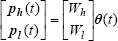
In this study we concentrate on the design of mechanisms in which joint angles are linearly dependent on the displacements of a small number of actuators. The number of actuators r is smaller than the number of the joints n. The relationship between the joint angles and the displacements of the actuators is assumed as follows:

where
Each joint of the mechanism is driven by a linear dependent drive (LDD) that transmits a linear sum of the actuator displacements to the same joint. An example of a LDD is shown in Fig. 1.

An LDD example
An example of a multi-joint underactuated mechanism is shown in Figure 2. The mechanism consists of a multi-joint manipulator, a LDD system and actuators. The LDD system mediates between the joints of the manipulator and the set of actuators. Each LDD has a structure as shown in Figure 1. The LDD system corresponds to the elements of matrix A of eq. (1).

An example of a mechanism with
3. Design of the LDD system
In this section we introduce two methods for design of a LDD system for a given set of joint motions. We will explain these approaches with the example of a gripper as shown in Fig. 3. Here, for simplicity, we consider a multi-joint planar gripper with two fingers that move in the two dimensional space and contain revolute joints with one degree of freedom. However, the proposed method can be applied easily to robots that operate in the three dimensional space.

Framework of designed mechanisms
The gripper has n joints that need to be actuated with r actuators via the designed LDD system, where n > r. The synthesized LDD system should actuate the finger joints in a way that will allow the gripper to accomplish a set of manipulation tasks with a group of rigid bodied objects of known size and shape. During each task, the object needs to be pinched by the two fingers and moved on a designated trajectory to a new position. For each point of the same trajectory the object should have an orientation which is given in advance. The objects need to come into contact with the finger tips (denoted as P1 and P2) at preliminary defined contact points (indicated as O' and O”). It is assumed that there is no slippage between the finger tips and the surface of the grasped object during the task execution. The set of tasks that need to be accomplished with the gripper is given in advance. The given set of movement trajectories and the desired orientation of the manipulated objects for each point of these trajectories are describes by eq. (2).

where

The relation between the velocities of the end effector and the joint angle velocities can be expressed as follows:

where J is the Jacobian matrix. We use equations (3) and (4) to obtain the time series of joint angle values for each point of the movement trajectories. The present study is focused on the design of prosthetic hands that usually have a small number of joints. Because of that, in this paper we concentrate on kinematic structures where only a single set of joint angles corresponds to each position and orientation of the end effector. The same method can be extended to redundant open chain kinematic structures by applying some constraints to determine the joint motion. However, this problem lies outside the scope of the present paper.
As specified in (1), the parameters of the LDD system can be designed if the linear relationship A between the joint angles of the mechanism and the inputs from the actuators for each point of all movement trajectories are known. We introduce two methods for decreasing the number of the actuators and for computation of the linear relationships A.
The first technique is called the principal component analysis (PCA) method. Initially, we express the movement of all joints of the synthesized gripper mechanism with principal components. Then, we apply the PCA procedure to the joint angle data set to analyse the contribution of each principal component to the movement of the end effector and to identify the principal components with the highest contribution. The number of the principal components with higher contribution is usually much smaller than the number of all principal components. Next, we compose a simpler model (called reconstructed model) where all joint motions are allied to the principal components with highest contribution and calculate the relations between these principal components and joint angles. The number of the principal components with the highest contribution determines the number of the independent actuators that will be used for actuation of the gripper mechanism. The calculated transfer coefficients between the principal components with highest contribution and the joint angles are used as the coefficients of the LDD system, and correspond to the displacement transfer constants between the actuators and gripper joints.
The second method for LDD design is based on the back projection for lost pixels (BPLP) approach [12]. Originally the BPLP approach was developed as an image interpolation technique for image restoration of damaged photographs that have missing pixels in a number of regions. In this study, we apply the BPLP approach to determine the contribution of each joint motion to the movement trajectory of the end effector. We compose an original high resolution data set (OHRDS) that represents the links between all joint movements and the trajectory of the end effector in the case when each joint of the manipulator is activated by a separate actuator. We also compose low resolution data sets (LRDS) with much smaller dimensions that represent the cases when only a few joints of the original manipulator are active while other joints are truncated. The contribution of the truncated joint angles to the position and orientation of the end effector is ignored. We create a sequence of LRDS by choosing different sets of active joints. We use the BPLP approach to compare the OHRDS with the composed LRDS and rank the reduction error for each LRDS. The reduction error expresses the inaccuracy of the trajectory of the end effector when only selected joint angles are considered. This way, the LRDS with minimum error is selected as the reconstruction LRDS. For the reconstruction LRDS we calculate the relationships between the active joint angles and all joint angles. These relationships correspond to the coefficients of the matrix A and respectively they are used for calculation of the coefficients of the LDD system. In this method the number of the joints in the set determines the number of the actuators. Each actuator is connected to an active joint of the set while the remaining n-r joints are connected to the same actuators via the LDD system.
The mechanisms designed with the PCA method are called principal component drive mechanisms (PCDM). We refer to the mechanisms designed by the BPLP based method as back projection for lost joints drive mechanisms (BPDM).
In the PCA-based method, we reconstruct the all joint motions with a selected small number of principal components, while in the BPLP-based method we select a small set of joint angles of the original kinematic structure to reconstruct all joint motions of the same kinematic structure. Below we explain each method in greater detail.
3.1. LDD design using principal component analysis
PCA provides a strategy for reducing complex data sets to a lower dimension and simplifying their structure. PCA is a method which converts a multivariate data set into a set of uncorrelated variables called principal components by orthonormal transformation [4, 6, 11]. We can define the contribution rate of each principal component by ordering them by eigenvalue, highest to lowest. If we neglect the components of lesser significance, the final data set will have less dimension (and a much simpler structure) than the original set. In our study, we apply the PCA procedure to the joint angle data set of manipulator motions. The principal components which have high contribution rates contain much information of the joint motions. This means that we can construct a set with a small number of selected principal components with high contribution rates that have the potential for reconstructing the joint motions with minimal loss of information. The covariance matrix V∈Rn×n of all the joint angles
When we calculate V, the average joint angle value is subtracted in advance from the joint value. The n sets of eigenvalues and eigenvectors are obtained by the use of the eigenvalue decomposition.

Here, λ
i
(λ1>λ2>…>λ
n
) is the eigenvalue and

The relation between the principal components

where W is the translation matrix of PCA.
In order to evaluate how strong the relation is between one principal component and the joint angles of the kinematic chain, we introduce an index of contribution rate. We can define the contribution rate C i for i-th principal component as follows:

C i indicates the proportion of the variance of the i-th principal component to the total variance of the joint angles. If there are principal components whose contribution rate C i is significantly lower than the other principal components, we can exclude these and model the gripper joint motion with a small number of principal components. The exclusion of the principal components with low C i leads to significant simplification of the initial model of the structure while the error caused by such simplification is quite small. If we group all principal components into two groups depending on their contribution rate eq. (8) can be presented as follows:
where

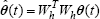
From (10) and (11) the reconstructed joint angles are represented as follows:

where
The reduction error

3.2. LDD design using BPLP algorithm
In the BPLP method we study the relationship between the joint angles

where

If we project the selected joint angles

Since the matrix W of the eigenvectors as defined with eq. (7) is an orthonormal matrix, the joint angles

Following the approach introduced in section 3.1, we group all principal components into two groups depending on their contribution and seek the relation between the r principal components with higher contribution rates

From (17) and (19) we obtain the following expression for

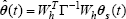
From (17), (18) and (20) we obtain the approximated joint angles
The reduction error

The reduction error

Equation (23) is equal to the equation (14) if the matrix Z is a unit matrix.
4. Design of the kinematic parameters of the underactuated gripper mechanism
The position and the orientations of the end effectors of the gripper are functions of the joint angles as shown in (3). These are also dependent on the kinematic parameters, e.g. link lengths.
The proposed approach for simplification of the gripper mechanism consists of two steps of optimization:
1/ Initially, we minimize the number of the actuators by applying the PCA or BPLP method,
2/ Then, we reduce additionally the error between the finger trajectory of the synthesized mechanism and the initial finger trajectory by varying and optimizing the link lengths of the synthesized underactuated hand mechanism. For that reason, in this section we deal with kinematic parameters as design variables.
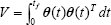
The relation between the position and the orientation of the end effectors and the kinematic parameters ξ = (ξ1, ξ2, …, ξ k ) can be described by the following equation:

where k is the number of the kinematic parameters. Note that the kinematic parameters do not change in the middle of the tasks. We execute the task, vary kinematic parameters and compare the performance of the hand until we achieve an optimal result. In this paper we assume that the given tasks are formulated with the trajectories that the end effectors of the gripper should follow. These trajectories depend on the way in which the joint angles change for a given task. Therefore, the reduction errors between the given joint angles and the reconstructed joint angles are also functions of the kinematic parameters. We define an index F to evaluate the errors in joint coordinate space.

The search for kinematic parameters that minimize the error index F can be formulated as an optimization problem:

We used the sequential quadratic programming (SQP) iterative method for nonlinear optimization on Matlab as an algorithm for optimization of the kinematic parameters.
4.1. Design of the kinematic parameters of the PCDM
The design procedure of the kinematic parameters of the PCDM is shown in Fig. 4. Here, F i is the value of the error index (25) for the kinematic parameters used in the i-th cycle, Fi-1 is the index calculated for the previous cycle and ε is a threshold value.
Step 0: Give the motion trajectory of task, the constraints and the initial value of the kinematic parameters (link lengths and orientation angle of the end effector of each finger).
Step 1: From the motion trajectory, obtain appropriate joint angles
Step 2: Apply the PCA-based method (introduced in 3.1) to the joint angles to obtain n dimensional principal components
Step 3: Select r principal components with the higher contribution rates
Step 4: Obtain the reconstructed joint angles
Step 5: Calculate the error between the original joint angles and the reconstructed joint angles. The error is defined with equation (25).
Step 6: Search the kinematic parameters which reduce the error and repeat the cycle from Step 1 to Step 5 until the evaluation value F i converges below given value ε.

Procedure of kinematic parameters design for PCDM
4.2. Design of the kinematic parameters of the BPDM
The design of the kinematic parameters of the BPDM can be done with the procedure shown in Fig. 5.

Procedure of kinematic parameters design for BPDM
The design process has the following steps:
Step 0: Give the motion trajectory of task, the constraints and the initial value of the kinematic parameters.
Step 1: From the motion trajectory, obtain the associated joint angles
Step 2: Select the joint angles to reconstruct the motions of the joint angles and truncate the other ones. Use equation (16) to represent the selected joint angles
Step 3: Project the selected joint angles to the r-dimensional eigenspace. Use equation (17) to calculate the variables
Step 4: Reconstruct the joint angles by the inverse projection to the eigenspace variables. The linear relationship between the reconstructed joint angles
Step 5: Calculate the error between the original joint angles and the reconstructed joint angles. The error is defined with equation (25).
Step 6: Search the kinematic parameters which reduce the error and repeat the process from Step 1 to Step 5 until the evaluation value: F i converges.
5. A gripper design example
In this section we provide a design example to demonstrate the proposed method and its practical viability. We will also show the procedure for searching kinematic parameters (link lengths and initial posture of the manipulator) that minimize the errors and reduce the evaluation index (25).
5.1. Prototype manipulator
In this example we consider a planar manipulator with two arms and six links, as shown in Fig. 6. In the same figure, l11, l12, l13, l21, l22, l23 denote the link lengths, θ1, θ2, θ3, θ4, θ5, θ6 are the joint angles and φ1 and φ2 are the initial orientation angles of the end effectors. There is a rectangular object in the work space for the manipulator. Fig. 6 represents the initial state of the manipulative task when there is no contact between end effectors and the object. The link lengths and the distances are presented in normalized form.

Prototype manipulator
5.2. Given task
In this task the end effectors need to move toward the object until they come into contact with the object. Then, the object has to be moved to a new position by following a given trajectory. It is assumed that there is no slippage between the finger tips and the surface of the grasped object during the task execution. The object is rigid and its shape does not change during the task accomplishment. The phases of completion of the task can be described as follows:
Phase 1: The right end effector moves toward the object and stops when it reaches the object wall.
Phase 2: The left end effector moves toward the object and stops when it reaches the object wall. At that moment, the object is pinched with both end effectors.
Phase 3: The grasped object is moved to the final position.
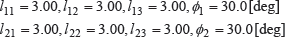
The task execution stages are shown in Fig. 7. The green line in Fig. 7 denotes the trajectory which the centre of the object follows. Although the manipulator with the two arms has six joints, we need only four variables to execute the task. This is a four dimensional task because the manipulator has two arms and each of them needs two independent variables to move the object on the defined trajectory to the end position. The kinematic parameters l ij and φ i (i = 1, 2, j = 1, 2, 3) are given as follows:

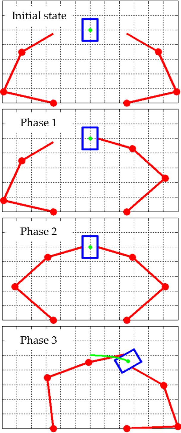
Procedure of the task
The contribution rates of the principal components are shown in Table 1.
Contribution rate

The table shows that the major principal components listed in first and second place have a sum contribution rate greater than 99%. This means that for the given task we can reconstruct quite accurately the joint motion of each finger with two independent variables. Therefore, the designed underactuated mechanism will have only two actuators that will activate all six joints.
When we design robot hands, we need to decide on the size of the links that build the fingers. We have to impose constraints on the kinematic parameters to avoid worthless solutions. The imposed constraints to the link lengths and the initial orientations of the end effectors can be decided by considering the relations expressed with equations (28) to (31).


Equation (28) defines the total length of each arm of the manipulator. Generally, the operating ranges of manipulators become small if the links near the finger bases are short. Non-equation (29) gives a prescription for avoiding the excessive reduction of the operating range. Non-equation (31) contains constraints to the initial postures of the end effectors. However, the constraints in (31) lose their meaning if the length of the finger tips becomes very small. To avoid the design of fingers with very short finger tips, we add some additional constraints with (30).
5.3. Design example for synthesis of a PCDM
As shown in Table 1, the principal components listed in first and second place have the highest contribution rates which indicate that the movement task can be performed successfully if the designed mechanism has two actuators that actuate all six joints. Therefore, in this section, we select these two principal components with high contribution rates to design the PCDM. Referring to (28) to (31), we select initial values of the link lengths l ij , and initial end effectors orientations φ i as presented in (32). Here, i = 1, 2 and j = 1, 2, 3.
After applying the procedure shown in section 4.1, we obtain the following values for the kinematic parameters:
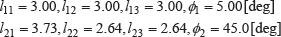
The shape of the designed manipulator is represented in Fig. 8. In order to evaluate how the given task will be accomplished with the designed manipulator, we calculate the error in the task coordinate space between the original trajectory and the trajectory of the designed manipulator as shown below:

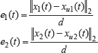
Here, Ex is the index of the error in the task coordinate space. x(t) is the vector of the desired trajectory of both finger tips over time t of the initial manipulator as specified with equations (32). x
u
(t) is the vector of the trajectory of both end effectors of the designed underactuated mechanisms for the same time t.

Designed PCDM with two principal components
In Table 2 we show the index value E x for the initial manipulator and the index value E x for the designed manipulator. In this case, each manipulator has two actuators connected to the manipulator joints via the LDD system.
Index of error in task coordinate space (PCDM: two principal components)
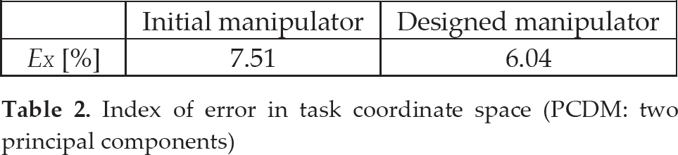
The result shows that the index of the error in the task coordinate space for the designed gripper has reduced by 19.6%. Fig. 9 shows the trajectory errors e1(t) and e2(t). In this paper the initial manipulator means the manipulator whose kinematic parameters are given with the equation (32). The designed manipulator means the manipulator whose kinematic parameters are designed by following the method presented in chapter 4.

Trajectory error between the initial manipulator and the designed PCDM with two principal components
5.4. Design example for synthesis of a BPDM
The initial values of the link lengths and the orientations of the end effectors were set with (32). In the BPLP algorithm, we need to choose a small set of joint angles and to evaluate the completion of the movement task. When we choose the joint angles θ2 and θ4 and apply the method presented in section 4.2, the kinematic parameters of the manipulator are as follows:

The designed manipulator is shown in Fig. 10.
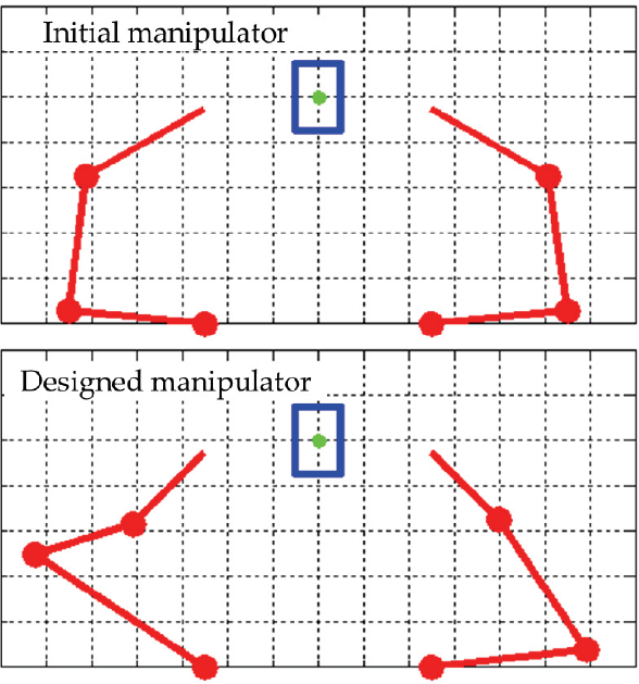
Designed BPDM when joints 2 and 4 are selected
In Table 3, we show the index values E x of the initial manipulator and the designed manipulator when they are driven by LDD, respectively. We applied formulae (34) and (35) to calculate these index values.
Index of error in task coordinate space for the BPDM: synthesized by selecting joints 2 and 4
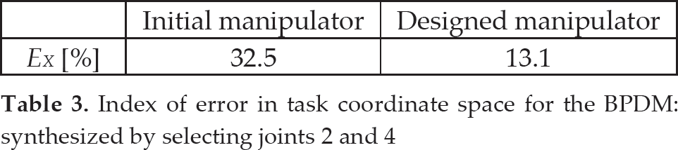
The index of the error in the task coordinate space for the designed manipulator is reduced by 59.7%. The trajectory errors e1(t), e2(t) the synthesized BPDM are shown in Fig. 11.

Trajectory error of the BPDM (selected joints 2 and 4)
When we choose joint angles θ1 and θ5 and apply the method of 4.2, the obtained kinematic parameters are as follows:

The shape of the designed manipulator is represented in Fig. 12.

Designed BPDM: (selected joints 1 and 5)
Index of error in the task coordinate space for the BPDM: (selected joints 1 and 5)
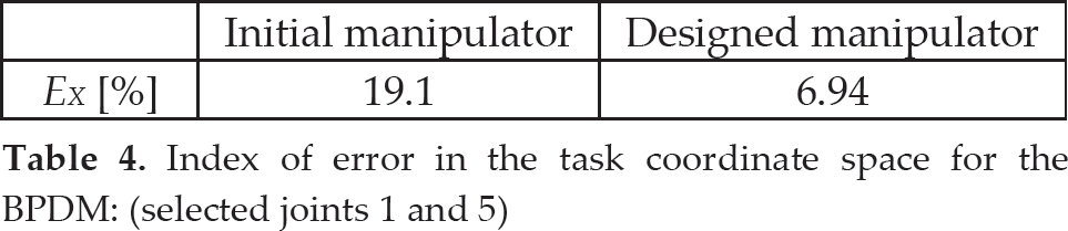
In Table 4 we show the index values E x of the initial manipulator and the designed manipulator when they are driven by LDD, respectively.

Trajectory error of the BPDM: when joints 1 and 5 are selected
The error index in the task coordinate space reduces by 63.7%. Fig. 13 shows the trajectory errors e1(t), e2(t) of the synthesized BPDM.
6. Discussion
6.1. Difference between the PCDM and the BPDM
If we design a PCDM and a BPDM with the same number of actuators for the same task, the BPDM is simpler than the PCDM. The LDD system of the PCDM is usually much more complicated because it needs to transfer a linear combination of all actuator inputs to each joint. By contrast, in the BPDM some joint angles are equal to the actuator inputs while the remaining joints are connected with the same actuator inputs via LDDs. On the other hand, in terms of the joint coordinate space, the accuracy of the PCDM is better than the BPDM.
PCDM and the BPDM also differ from each other by the control systems they require: the inputs of the PCDM are the principal components and for calculation of these principal components we need information regarding all joint angles. On the other hand, the inputs of the BPDM are selected joint angles and we need only the selected joint information to measure the inputs.
6.2. Kinematic parameters and errors in task coordinate space
In this study we consider a gripper with a structure that consists of links connected in series via revolute joints. The displacement Δ

where
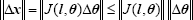
Here the Jacobian matrix J is the function of the link lengths and the joint angles. Generally, Jacobian matrixes of serial manipulators with revolute joints can be presented with the product of the multiplications of the joint angle functions and vectors of the link lengths, i.e. the Jacobian matrix can be rewritten in the following way:

where R is the matrix which variables are

The elements of the matrix
7. Conclusion
We introduce a task-based method for design of undeactuated gripper mechanisms for a set of grasping tasks. The tasks are defined by the trajectories of the end phalanges of the gripper. At the beginning, it is assumed that the given movement tasks are performed by fully actuated grasping mechanisms. We propose two methods that allow the approximation of the joint motion with a small number of independent variables. The proposed approaches allow the synthesis of underactuated mechanisms that have fewer actuators than joints. The joint angles of the synthesized mechanism are linearly dependent on the displacements of the actuators. The designed mechanisms have simpler structures and can perform the specified motion tasks with high accuracy. We also propose a method for calculation of the kinematic parameters of the underactuated gripper mechanism for the selected tasks. We present simulation results that demonstrate the effectiveness of the proposed approach. In this paper we deal with problems of kinematics, while further study considering the problems of statics is ongoing.