
Abstract
This paper presents the behavior of two finger based micro gripper which is made of Ionic Polymer Metal Composite (IPMC), an Electro Active Polymer (EAP). An IPMC shows great potential as high-displacement and light weight actuator. Low mass force generation capability is utilized for micro gripping in micro assembly. IPMC responds to low voltage in the range of 0-3V. The material contains an electrolyte which transport ions in response to an external electric field. IPMC actuation for micro gripping is produced by deflecting material according to bending moment theory. An external electric field generated by suitable RC circuit causes this deflection. It is found that an IPMC actuates from 1–5 seconds. The maximum jaw opening and closing position of micro gripper are found to be 5 mm and 0.5 mm respectively. The effect of tempearture, as observed, shows that the acceptable limit varies from 23.1°C to 30.4°C while an IPMC is in operation. An experimental proto type is developed for evaluation of performance.
1. Introduction
A micro factory test bed demands a light weight and compact sized micro part handling device with artificial tendons and sensors for micro manipulation, i.e. it requires a micro manipulator with micro gripper which is an essential part of “Micro factory test bed”. To cater this type of need in micro manufacturing environment, a project is pursued by our institute for development of “Micro factory test bed”. A number of micro robots with different DOFs are reported by H. Bleuler et al. (2001) and X. J. Liu et al. (2005). After these studies, it has been found that the conventional mechanisms have limitations in handling the miniature parts in terms of flexibility in part handling (M. Tanaka, 2001 and A. Burisch et al., 2007). As micro part handling device heavily depends on reliability and durability of the actuators and sensors, various types of actuators and sensors like shape memory alloy (SMA), silicon, piezoelectric, ionic polymer metal composite (IPMC) and electro active polymer (EAP) are studied which have been published by S. Tadokoro et al. (2002) and C. Bonomo et al. (2005). From the research work of K. J. Kim & M. Shahinpoor (2002), we are familiar that IPMC is a special kind of polymer which responds to an electrical stimulus by exhibiting a large bending strain without utilizing conventional motor while it is in operation. These properties have elevated IPMC to provide a cutting-edge technological revolution over a wide spectrum of applications. Regarding application of IPMC, M. Shahinpoor et al. (2004–2008) has significant contribution towards development of the four IPMC fingers based micro gripper and biomimetic device, mini-pump, heart compression device, eight finger synthetic muscles. Efforts have also been made in the development of a variety of microgrippers and their applications in MEMS, micro-optics, compliant and passive microgripper, IPMC micro gripper by B. Kim et al. (2003), K. Kim et al. (2004), N. Dechev et al. (2004) and R. Lumina et al. (2008) respectively.
M. Y. F. Kwok et al. (2000) have analysed micro nafion actuators for cellular motion control and underwater manipulation. W. Zhou et al. (2001) and J. W. L. Zhou et al. (2002) have studied the neural fuzzy based control system for manipulating the micro nafion and ionic conducting polymer film actuators (ICPF). Y. Bar-Cohen et al. (2000 & 2001), X. Bao et al. (2002) and S Sherrit et al. (2002) focused on characterization methods, macro and micro modeling of IPMC and piezo electric resonators characterization. A remarkable effort have been made to use feed back control system, PID control system, adapative control system for controlling IPMC and micro positioning of IPMC by K. Mallavarapu (2001), N. Bhat et al. (2003), B. C. Lavu et al. (2005) and K. Yun et al. (2006) respectively. Regarding exploration of low temperature characterization of IPMC and control of micro manipulation through force sensing method using IPMC, have been published by J. W. Paquette et al. (2005) and L. Zhe et al. (2006) respectively.
Modeling, simulation and control of IPMC have been studied by T. A. Bowers (2004). The bending behaviour of IPMC beam using concentrated ion boundary layer have been worked by W. A. Lughmani et al. (2009) and recently, research work on high temperature polymer capacitors for aerospace applications have been explored by C. K. Landrock et al. (2010).
For further application about handling of miniature components in micro factory test bed through flexible link, we found that one promising approach is to develop micro fingers of end-effectors using ionic polymer metal composite (IPMC) so that they are better suited to precisely handle and manipulate micro components. IPMC based microgripper has compliant beams that allow the gripper tips to bend, and grip the micro object. An IPMC shows reliable actuation and consume reasonable energy. The polymer-based actuator requires low voltage (0–3V). A typical IPMC has a thin (approx. 200 μm) perfluorinated ion exchange base polymer membrane with metal electrodes (5–10 μm) fused on either side. As a part of the manufacturing process, this base polymer is further chemically coated with metal ions that comprise the metallic composites. It also responds in wet/dry condition. An IPMC is usually kept in a hydrated state to ensure proper dynamic operation. In such an aqueous state, it exhibits large bending. An applied electric field affects the cation distribution within the membrane, forcing the cations to migrate towards the cathode. This change in the cation distribution produces two thin layers, one near the anode and another near the cathode boundaries. The potential is generated by changing the potential electric field on cluster of ionic strips that provide the actuation of the strips.
The objective of this paper is to discuss the behavior of two IPMC fingers based micro gripper for handling the miniature parts. For this purpose, the deflection of IPMC is obtained using suitable RC circuit by providing the electric potential and the force is generated through bending moment. The deflection and force behaviors are utilized for developing the micro gripper. The different internal forces of IPMC are also studied and these are applicable in micro domain for grasping the object. An experimental setup for controlling the ionic strips is developed where deflection and force capabilities of miniature components are tested. The effect of temperature is also observed. Subsequently, the performance of two IPMC fingers based micro gripper is evaluated for assembly.
2. Electro mechanical characteristics of IPMC
2.1. Theoretical deflection characteristic of IPMC
The major challenge is to characterize IPMC such that it ensures stability during the actuation. IPMC has two parallel platinum electrodes and polymer between the electrodes. The material usually contains an electrolyte, involved in the movement of ions in response to an external electric field. The field controls migration or diffusion of ions which results in an internal stress distribution. This internal stress distribution induces a wide variety of strains ranging from contraction to bending. For obtaining the deflection, W. Yim et al. (Edited by K. J. Km et al, 2007) had made an attempt with an electromechanical model for segmented IPMC configuration but our contribution is towards developing an electromechanical model by assuming uniform length of cantilever configuration of IPMC. Accordingly, a uniform cantilever bending configuration of an IPMC with input voltage V i (t) is shown in Figure 1 where the deflection angle varies from initial angle θ i to final angle θ f . The RC model for deflecting the IPMC is obtained by Kirchhoff's law. The clumped RC model relates the input voltage V i (t) to the electric charge Q i (t) and the current I i (t) as shown in Figure 2 where R1 and R2 are resistors, C is the capacitor.

Cantilever configuration of IPMC

Basic RC model related to input voltage
By making the assumption of R1<R2 and 1<R2, the basic RC model characteristic equation is used as

If there is no initial current flow and we take the Laplace transformation


The basic charge equation is

After taking the Laplace transformation,


During migration of cation towards cathode in the polymer network, the bending moment M i (s) is modeled using a simple first-order model and it is

where, M i (s) is the bending moment applied to the IPMC, K u and τ u are parameters that can be found using the experimental data. Here, K u is the gain and τ u is the time constant that characterizes the speed of bending moment generation. By assuming unit gain, the experimental data of the curvature versus voltage within 5 seconds is collected as shown in Figure 3.

Experimental data of curvature of IPMC with voltage

where, τq = R2C and K=KuC

where, a0 = (τq+τu/τqτu) and a1 = (1/τqτu
Therefore,

where, a+b=a0 and ab = a1
Taking inverse Laplace,

where, k1 = K/(b - a) and k2 = K/(a - b)
The deflection θ(t) of IPMC can be defined as

By using (10), we get

The graph of deflection with time is shown in Figure 4. The deflection behavior is exponentially decreasing with time due to bonding of sulfonic ion exchange group in the backbone structure of IPMC.

Theoretical deflection response of IPMC with time
2.2. Theoretical force characteristic of IPMC
For obtaining the force model, the input voltage to the IPMC is provided. The force model F(t) for cantilever beam of uniform length L is written as

Substituting M i (t) from (10),

where, F1(t) = [k1Vi(t)/L] and F2(t) = [k2Vi(t)/L]
The force response with time is shown in Figure 5. The force response of IPMC shows an exponential behavior with maximum value of 10 mN. The generated force is controlled by an input voltage. The voltage provides the movement of charge transport in the polymer network. For analysis of the micro gripper, two ionic strips are placed with sufficient space between them so that they have enough flexibility for opening and closing operation. Bending of the ionic strip in cantilever configuration is obtained by an input DC voltage ranging upto 3V. The bending behavior of each ionic strip is derived through bending moment theory (L. L. Howell, 2001). The kinematic behavior of micro gripper using IPMCs is shown in Figure 6. When a DC voltage varying from 0 to 3V is applied to the ionic strip independently, a change in the bending behavior is noticed. A reverse behavior is obtained when the polarity is changed (Figure 6). Both fingers close together and maximum jaw closing position is 0.5 mm. The ionic strips act as fingers to grasp the object. Since these strips are quite wet, the micro part may stick to the fingers because of dominating inertial and adhesive forces in the micro domain. Adhesive forces arise primarily from electrostatic attraction, Vander-Waals forces and surface tension forces. The magnitude of these forces depends on the size of the object. The size of the manipulated object is usually ⩽1 mm in a single dimension. The behaviors of dominating forces during micro gripping mechanism using IPMC are calculated as shown in Figure 7.
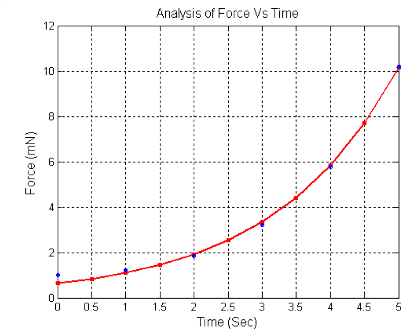
Theoretical force response of IPMC with time

Kinematic behavior of micro gripper using IPMCs

Different forces arising in micro domain of IPMC
The dominance of adhesive forces in the end effector of manipulator is applicable to a micro object in the pickup operation. Electrostatic and Vander-Waals forces may attract the object to the extent that the object moves towards end effector in operation. The magnitude of adhesive forces is proportional to the size of the object radius. When the size of an object is less than a certain threshold value, the overall adhesive forces and Vander-Waals forces become greater than the gravitational force acting on the object. The overall adhesive or Vander-Waals force depends upon mobility of charge transport in the solvent network.
The movement of charge transport in polymer network shows change in volume or shape in response to perturbation of the balance between repulsive intermolecular forces that allow expansion and contraction of fingers. Repulsive forces are usually electrostatic or hydrophobic in nature, whereas attraction is mediated by hydrogen bonding or Vander-Waals interactions. The bonding between these counteracting forces, can thus be controlled by changes in parameters such as solvent or gel composition, cations and anions etc. (A. Lisowska-Oleksiak et al., 2001). The electric field induced charge lies between non-polar and polar regions along the strip. The strips appear to exhibit a little more stiffness and is less yielding primarily due to the composite metal portion (Pt/Gold) that interacts with the polymer matrix when an electric field is induced between solvent and cation.
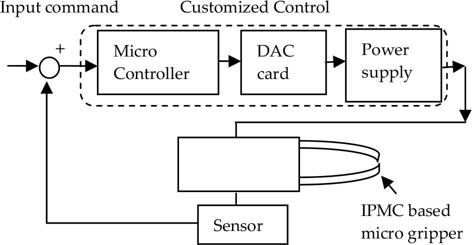
3. Experimental test setup
The schematic layout for testing of a micro gripper using an IPMC is shown in Figure 8. IPMC strips are cut in dimension of 30mmx6mmx0.2 mm and the samples with two metal coatings on the Nafion membrane are used. Two IPMC fingers based micro gripper is held in a mild steel clamp. An electrical signal is provided by a micro controller which is controlled by an input command. An input voltage ranging from 0–4 V is supplied through a customized controller (Figure 8). A sensor (Model-OADM 20S4460/S14F from Baumer Electronic) is used to measure the tip displacement of the IPMC fingers. The position measurement is then fed to a 16-bit digital-to-analogue (D/A) converter. The pulse rate is controlled by Docklight V1.8 software through RS-232 port. Each sinusoidal pulse with a sampling rate of 0.05 sec is given to the IPMC fingers. The fingers bend on positive side and each finger is induced with opposite polarities to each other. They clamp together and hold the object.
Schematic layout for control of micro gripper
4. Result and Discussion
The actual test setup is shown in Figure 9 where displacement sensor is placed at 60 mm from IPMC clamp position and the sampling rate is measured through function generator and transferred to IPMC. By applying a small voltage between 0-4V through DAC, ionic strips bend towards positive side. The reverse effect can also be achieved by changing the polarity. The experimental values of deflection are noted on positive side as shown in Figure 10. It shows that IPMC strips allow displacement upto 14 mm corresponding to time. It is observed that the deflection behavior has similar trend as compared to the theoretical model.
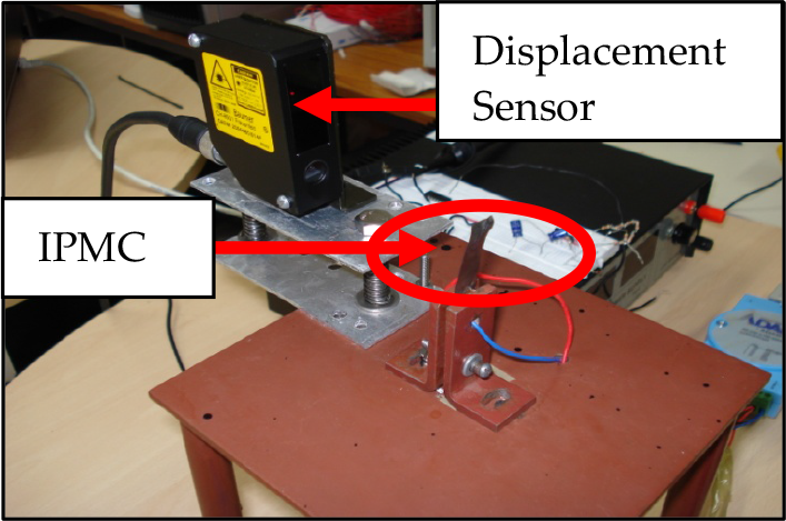
Experimental Setup for testing of IPMC

Deflection behavior of IPMC with time
The force response of IPMC strip upto 10 mN is shown in Figure 11. It is observed that tip force varies exponentially as compared to theoretical values due to presence of wet moisture in the composite membrane which interacts with the polymer network and cations when an electric field is applied.

Force response of IPMC with time
When a power supply (0–3.5 V) is provided to IPMC, responses are shown in Figure 12. It is observed that deflection behavior shows steady state response with straight polarity and an opposite trend follows when polarity is reversed. Subsequently, when power supply is in off mode, the trend is slightly lower due to interaction of cations with the polymer network in dry environment where typical perfluorinated sulfonic ion-exchange is bonded with ionic groups in IPMC backbone structure. For improving the quality of actuation, the voltage-current is amplified with reasonable amplification factor so that the desired characteristics can be obtained.
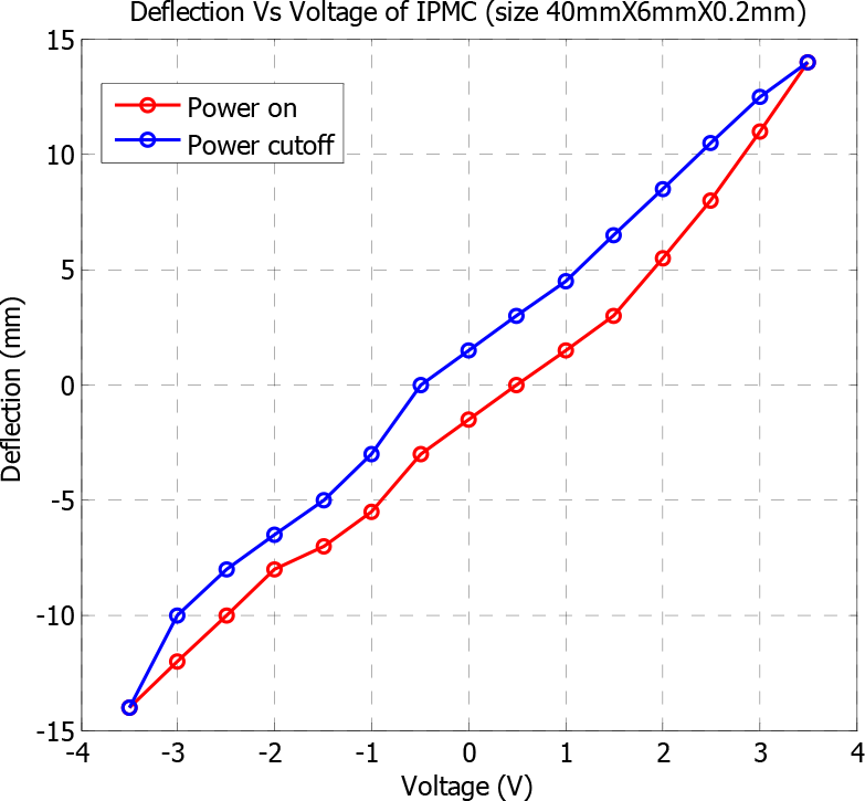
Responses of IPMC in different operation modes with voltage
During actuation, IPMC gets upto 20 mA through DAC card. Using customized amplifier control system, current is achieved in the range of 220 mA for large deformation of ionic strip. The current response with voltage is measured along the strip as shown in Figure 13. It highlights that the output input relationship follows Ohm's law significantly. This has been providing the sufficient input signal for large deformation of composite membrane.
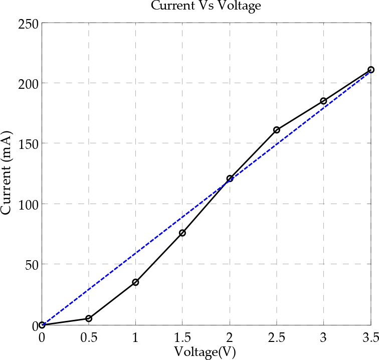
Current response of IPMC with voltage
The IPMC is capable of driving the system effectively upto 1.7 seconds. Beyond 1.7 seconds, it shows a gradual settlement in its behavior when voltage is increased and occurrence of free vibrations is noticed. This phenomenon of settling down is called as settling time. Now, our aim is to decrease the motion time of the total system. To achieve this, we first give 1.3 Hz as input to the IPMC by adjusting input command by means of customized micro controller. Some changes in behavior are observed. Then, we instantly readjust the frequency to a higher value of 3.7 Hz. Some amount of retained frequency of the previous input and the new frequency together reduces the settling time of the total time period to considerable extent.
For measurement of temperature effect inside the strip, forward looking infra red (FLIR) thermographs are taken through FLIR camera during operational condition of an IPMC. It is observed that the hot stop is propagated from the fixed end in the IPMC strip (Figure 14). The temperature difference is about 7.5°C when a DC voltage of 3 V is applied. The temperature range varies from 23.1°C to 30.4°C which is acceptable with in applied voltage as shown in Figure 15. It is observed that as temperature gradually increases from a minimum of 23.1°C and reaches upto a maximum temperature of 30.4°C, then the temperature decreases proportionally after attaining the maximum value.

FLIR thermographs at initial stage and after testing of IPMC during operation

Temperature distribution of IPMC during operation
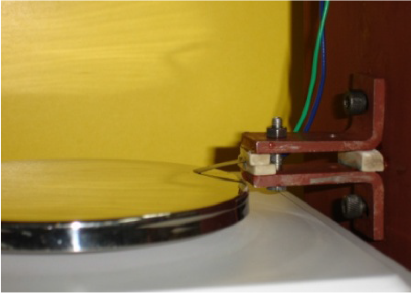
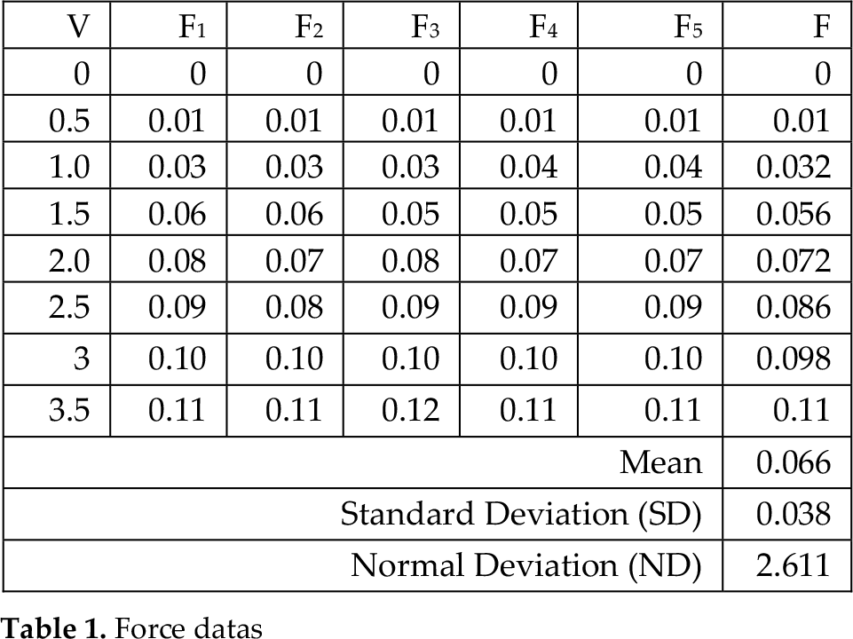
For repeatability analysis, the composite membrane is held in holding fixture as shown in Figure 16. The low force measurement load cell is used to measure the load ranging from 0.01–100g. Voltage is also measured using multimeter while ionic strips are in operation. The experimental values are noted as shown in Table 1. For calculation of standard deviation (SD), five different force values (F1, F2, F3, F4 and F5) corresponding with voltage range (0–3.5V) are taken. After that, we have calculated the force mean value from five different readings. From this corresponding mean value, the standard deviation (SD) is obtained. The normal distribution curve through variance (σ) of standard deviation is as shown in Figure 17. The confidence level of ionic strip during operation is 97.4%. This confidence level of each IPMC highlights that these ionic strips have reasonable potential in a micro industry. Consequently, the micro gripper is constructed through this type of actuator and tested.
Testing setup for tip force response

Standard normal curve of an IPMC
Force datas
After all these observations, the overall specifications of customized IPMC, as fingers for micro gripper, are shown in Table 2. These behaviors help the IPMC strip to play a very important role as a micro actuator in micro gripping system when system performs pick and place operation. Manipulation task requires precise positional information of the end-effector in the reference frame. With advanced fabrication techniques, it is possible to fabricate micro tips to build the fingers of the micro gripper.
Overall specification of IPMC

A compliant gripping system along with control system is developed as shown in Figure 18. The mimicking of fingers is done through electrical actuation instead of conventional motor. Each finger can be actuated individually so that dexterous handling is possible, allowing precise end effector positioning. When fingers are in operation, the maximum displacement is in the range of 5 mm. The maximum jaw opening and closing positions for micro gripper are found to be 5 mm and 0.5 mm respectively. The fingers can hold the object having weight upto 10 mg. The micro gripper has demonstrated handling capabilities for micro components like pin in bread board (size- diameter 1mm, length 10 mm and material- mild steel). Although this device has exhibited acceptable handiness, they have potential of handling numerous millimeter-scale components, requiring complex fabrication and assembly.

Micro gripper for lifting operation using IPMCs
5. Conclusion
In this paper, the deflection and force response of an IPMC strip with the capability of handling the miniature component is discussed. The main aim to use an IPMC strip in a micro gripper is for holding and lifting a flexible miniature component in a micro factory test bed without utilizing any conventional motor. The actuation of micro gripper is controlled by a customized control system and is designed to provide uniform grasping force over the surface of the jaws. The effect of temperature on IPMC as seen from experimental analysis suggests that the system is capable of bending behavior in normal room temperature. This potential shows the considerable parameter for saving the downsized production system in terms of energy, space and resources. The miniature part is handled within micro assembly and is precisely positioned through well equipped transfer arm. In this paper, new concept of integration of micro gripper is highlighted for the pick and place operation in bread board. It significantly contributes towards realization of micro factory test bed concept in micro manufacturing.
Footnotes
6. Acknowledgement
The authors are grateful to the Director, Central Mechanical Engineering Research Institute (CMERI), Durgapur, West Bengal, India for providing the permission to publish this paper. The project is financially supported by the Council of Scientific and Industrial Research, New Delhi, India under eleventh five year plan on “Modular Re-configurable Micro Manufacturing Systems (MRMMS) for Multi Material Desktop Manufacturing Capabilities (NWP-30)”. Mr. Souvick Chowdhury (Project Assistant) is also involved in this research work along with the authors.