
Abstract
Symmetric micro-gripper mechanism is very easy way to destroy the micro-components or parts for nonuniform force in the processing of micro-assembly. Aiming at the requirements of micro-assembly for the microtubule (diameter of 0–200 μm) components, a new type of asymmetric flexible micro-gripper mechanism based on flexure hinges was designed and studied. The asymmetric micro-gripper mechanism was driven by piezoelectric actuator, whose output displacement was amplified and transmitted by flexure hinges, and the flexible parallel four-bar mechanism was used to ensure that the micro-clamp moves and is held parallel. The displacement amplification ratio of the asymmetric flexible micro-gripper mechanism was deduced theoretically, and the finite element analysis and the experiment were also carried out to study the displacement amplification ratio in detail. The experiment results show that the displacement amplification ratio of the asymmetric flexible micro-gripper mechanism is 4.16, compared with the finite element analysis result and the theoretical calculation result; the error between them is 1.89% and 5.67%, respectively. The experiment results also show that the step-wise resolution of the micro-gripper is 7.50 μm, and the output force of the right micro-clamp was measured at 0.28 N. The asymmetric flexible micro-gripper mechanism is able to perform the micro-assembly tasks for the microtubule parts, and it is helpful to design this type of micro-gripper mechanism.
Introduction
As a result of the development of microelectromechanical systems (MEMS), precision machinery processing, and manufacturing technology, more and more micro-components and parts are produced, and these micro-components and parts could only be assembled in the micro-assembly system. In the micro-assembly system, micro-gripper is the key component to finish the assembly actions, such as pickup, handling, assembly, and release. For the fact that most micro-components and parts are small, light, thin, and brittle, 1 the traditional micro-gripper with large rigidity and uncontrollable clamping force is unable to apply in the micro-assembly system directly. The new type of micro-gripper based on flexure hinges, which is driven by piezoelectric actuator, has obtained widespread interest and research in recent years because of the fact that this type of micro-gripper has distinct advantages, such as no mechanical friction, high precision, and fast response. On the other hand, the micro-displacement of flexure hinge is resulted by the micro elastic deformation of the weak part and its self-recovery features of the own structure, and the range of the micro-displacement is generally between a few microns and tens of microns. To satisfy the requirements of the micro-assembly system, it is necessary to use flexible amplification mechanism to amplify and transmit the micro-displacement of flexure hinges.
Presently, the commonly used micro-displacement amplification mechanism includes a multi-stage lever amplification mechanism,3,4 a differential lever amplification mechanism, 5 and a bridge-type amplification mechanism. 6 The principle of the lever amplification mechanism is simple and easy to implement, and in theory, the output is a linear amplifier for input, but the amplification ratio of the lever mechanism is highly limited, while error accumulation and oversize would be caused if the multi-stage lever amplification mechanism was used. 7 The amplification ratio could be enlarged distinctly by the differential lever amplification mechanism, the application scope of which is limited for the complicated analysis of structure, and it is still unable to achieve the compact structure. The bridge-type amplification mechanism, which is designed by the principle of triangular amplification, has a large amplification ratio and a compact structure, but it is difficult to process. 8 On the other hand, many have studied the micro-gripper mechanism from different aspects. Han et al., 9 Li and Chen, 10 and Hao et al. 11 designed the symmetrical micro-gripper with flexure hinges; Chen et al. 12 and Feng et al. 13 developed a micro-gripper with two-stage amplification that was driven by piezoelectric actuator; Eric and Metin 14 studied a magnetostrictive micro-gripper system and pointed out the test plan; Hamed et al. 15 proposed a new type of electrostatic micro-gripper by taking use of capacitive touch sensor for applying the biological cell field; El-Sayed et al. 16 designed a kind of micro-gripper mechanism with piezoelectric bimorph; and Liu and Liu 17 studied the micro-piezoelectric stepping mechanism based on the inverse piezoelectric effect and a new type of micro-gripper mechanism that was driven by piezoelectric actuator using the cantilever beam.
Summarizing the studies above, most micro-gripper mechanisms used the symmetric structure, which has some advanced features of double amplification of displacement, and they could meet the requirements of clamping and assembling micro-parts with larger geometry. On the contrary, the disadvantages of the micro-gripper mechanism with symmetric structure are also obvious, which is that the movement of both sides of the micro-clamps cannot be completely synchronous for the inevitable error that existed in the processing of manufacturing and installation. Therefore, the micro-parts could be destroyed easily by the nonuniform force that is caused from the inconsistent output displacement of both sides of micro-clamps. In order to satisfy the requirements of micro-assembly for the microtubule components (diameter of 0–200 μm), a new type of asymmetric flexible micro-gripper mechanism based on flexure hinges would be proposed and studied. The asymmetric micro-gripper mechanism is driven by the piezoelectric actuator. In the processing of micro-assembly for microtubule components, one side of the micro-clamp could clamp, hold, and move parallel by making use of the flexible parallel four-bar mechanism, while the other side of micro-clamp is fixed. The asymmetric micro-gripper mechanism could carry out the micro-assembly for the microtubule components without damaging.
Design of asymmetric micro-gripper mechanism
Overall structure
A complete micro-assembly system mainly consists of a fixed platform, a pre-tightening device, a piezoelectric ceramic actuator, and a micro-gripper mechanism. The overall structure of the micro-assembly system is shown in Figure 1.
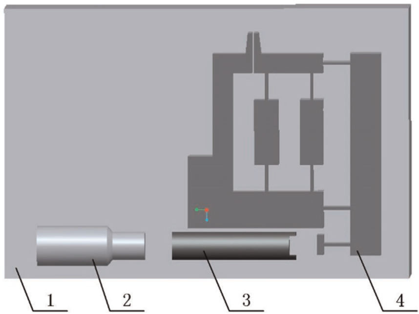
Overall structure of the micro-gripper system. 1: fixed platform, 2: pre-tightening device, 3: piezoelectric ceramic actuator, and 4: micro-gripper mechanism.
The fixed platform was used to locate and install all components of the micro-assembly system. The responsibility of the pre-tightening device is to ensure the piezoelectric ceramic actuator and the micro-gripper mechanism are tightly in contact and perform the clamping and holding operation for the microtubule parts with different sizes by adjusting the initial distance between the two micro-clamps of the micro-gripper mechanism. All driving force for the micro-gripper mechanism is supplied by the piezoelectric ceramic actuator, which is used to generate deformation under the driving power, and the deformation could be regarded as the input displacement for the whole micro-gripper mechanism. The input displacement is amplified and transmitted by the micro-gripper mechanism based on flexure hinges, and the final displacement is output by the micro-clamp. The suitable microtubule components or parts could be assembled in this micro-assembly system.
Design of the micro-gripper mechanism
The micro-gripper mechanism is constituted by a displacement input unit, a displacement amplification unit, a flexible parallel four-bar unit, and a pair (left and right) of micro-clamps (Figure 2). The responsibility of the displacement input unit is to transmit the driven force and the deformation that is caused by the piezoelectric ceramic actuator. The displacement amplification unit could be used to amplify the input displacement by making use of a lever. When the microtubule components are clamped, held, or assembled, the left micro-clamp is fixed and immovable, while the right side of micro-clamp is movable, and the microtubule components could be clamped, held, and assembled by the movement of the right micro-clamp, which is used to output the amplified displacement. In order to guarantee that the microtubule components could not be destroyed by the nonuniform force of both sides of micro-clamps, the flexible parallel four-bar unit is performed to make the movement of the right side of micro-clamp parallel to the left immovable micro-clamp in the processing of clamping, holding, or assembling.

Structure of the micro-gripper mechanism: (a) structure and (b) geometry.
In the premise of meeting the demand of clamping or assembling the microtubule parts, it is necessary to ensure the safety of the micro-gripper mechanism, which is to say, the maximum stress of the thinnest thickness of the flexure hinge should not exceed the yield strength (δs ) of the material. Considering the strength and the flexibility requirements of the micro-gripper mechanism, the device could be fabricated in the processing of wire-cut electrical discharge machining (WEDM), and the machining current must be small in order to avoid the phenomenon of stress concentration. The material was chosen as the No. 45 steel, and its main performance parameters are as follows:
Elastic modulus, E = 210 GPa;
Tensile strength, σb = 600 MPa;
Yield strength, δs = 355 MPa;
Poisson’s ratio, μ = 0.27.
Displacement amplification ratio and geometry
Calculation of the displacement amplification ratio
Assuming that the output displacement of the piezoelectric ceramic actuator is marked as Din , the flexure hinge H1 is compressed at the X axial direction, and the amount of compression could be marked as Δ 1 (Figure 3). The actual input displacement is D 1. Apparently, there is a relationship, as shown below

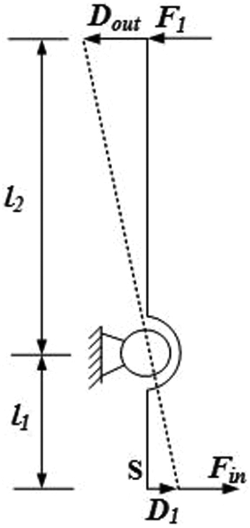
Motion diagram of the displacement amplification mechanism.
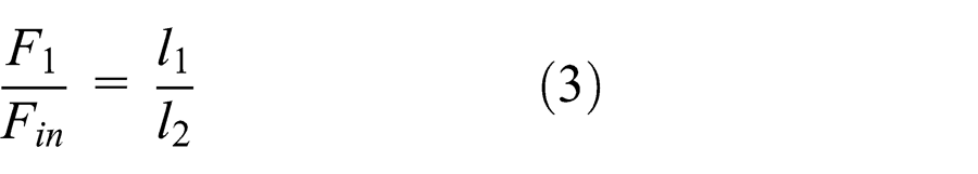
The displacement amplification unit actually is a lever, and then some proportional relation could be obtained based on the lever principle as follows

The acting force Fin , which is caused by the piezoelectric ceramic actuator’s deformation, is calculated as the following formula

where
According to the literature,
18

where E is the modulus of elasticity, b is the width of the flexure hinge, and t is the minimum cutting thickness of the flexure hinge.
When the microtubule components are operated by the micro-gripper mechanism, the movement of the right micro-clamp must be parallel to the left micro-clamp. The microtubule components could not be destroyed by the nonuniform force that is caused by the unparalleled movement of the right micro-clamp. Therefore, the flexible parallel four-bar mechanism is used to make sure that the movement of the right micro-clamp should be parallel to the left micro-clamp in the processing of assembling (Figure 4). The flexible parallel four-bar mechanism has been widely used in the precision instruments for its excellent features of guiding accuracy. 19 The flexible parallel four-bar mechanism uses flexure hinges instead of the traditional hinges, and it is more suitable to be applied in the asymmetric flexible micro-gripper mechanism.

Flexible parallel four-bar mechanism: (a) geometry and (b) motion diagram.
According with the theory of elastic cantilever beam and the related literature, 20 the output displacement of the flexible parallel four-bar mechanism could be calculated as follows
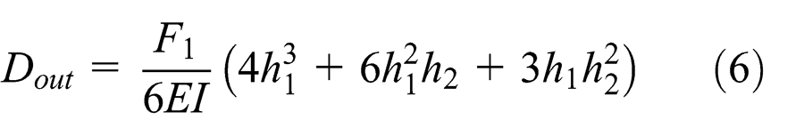
where I is the moment of inertia, I = bt 3/12.
Substituting formulas (1)–(5) into formula (6), the displacement amplification ratio is calculated as the following formula

where
Geometry design of the micro-gripper mechanism
The three-dimensional model of the asymmetric flexible micro-gripper mechanism was built in Pro/E, and then the model was processed with static simulation by importing the model into ANSYS 14.0. All key parameters of the asymmetric flexible micro-gripper mechanism were revised several times according to the simulation results based on formula (7), and then the final dimensions of main structure parameters are shown in Table 1.
Main structure parameters of the micro-gripper mechanism.

According to formula (7) and the parameters in Table 1, the displacement amplification ratio of the asymmetric flexible micro-gripper mechanism could be calculated theoretically, and the theoretical calculation result is that k = 4.41.
The corresponding model that used the same parameters in Table 1 was processed by the finite element analysis (FEA) in ANSYS 14.0. Assume that the initial input displacement was 0.01 mm, which acted on the axial direction of the X axis of the displacement input unit, and the simulation result shows that the finial output displacement of the right micro-clamp is 0.042374 mm. The FEA simulation result is shown in Figure 5. The displacement amplification ratio of the FEA simulation result is that k = 4.24, and the error between the theoretical calculation result and the FEA simulation result is 3.85%. The reasons of the error between the theoretical calculation result and the FEA simulation result mainly include the following: the theoretical calculation only considered the deformation that occurs in the notch of flexure hinge, while the deformation of other parts was all ignored, and at the same time, the internal stress was also ignored.

FEA simulation of displacement amplification of the micro-gripper mechanism.
The maximum stress of the micro-gripper mechanism is 260 MPa, which is less than the yield strength δs (355 MPa). Therefore, the micro-gripper mechanism could work safely.
There is another result, which is that the movement of the right micro-clamp is indeed parallel to the left immovable micro-clamp, which could also be found easily in Figure 5.
According to the FEA simulation result k = 4.24, if the piezoelectric ceramic actuator is suitable and the output displacement Din is in the range of 0–50 μm, then the micro-gripper mechanism could carry out the micro-assembly task for the microtubule components in the diameter range of 0–200 μm.
Experiment verification
Experiment condition
In order to verify the performance of the asymmetric flexible micro-gripper mechanism, it is necessary to carry out the experiment for the micro-gripper mechanism. The experiment test system mainly consisted of a driven power, a piezoelectric ceramic actuator, a laser measurement instrument, and the asymmetric flexible micro-gripper mechanism. The details of equipment used in the experiment are as follows:
HPV-3C of Boshi, driven power (Model Number HPV-3C; Boshi, China);
VS12/60 of Boshi, piezoelectric ceramic actuator (Model Number VS12/60; Boshi, China);
LK-H020 of KEYENCE, laser displacement sensor (Model Number LK-H020; KEYENCE, Japan).
HPV series was selected as the driven power, which is suitable for the piezoelectric ceramic actuator. VS12 series was selected as the piezoelectric ceramic actuator, whose specifications are φ12 mm × 60 mm, and its nominal displacement is 60 μm when the piezoelectric ceramic actuator is driven by the maximum voltage of 150 V. LK-H020 of KEYENCE was selected as the laser measurement instrument, and its precision is 0.02 μm.
In the processing of the experiment, the driven power was first adjusted to output different voltage, and then different displacement Din was generated by the piezoelectric ceramic actuator when it was driven by a different voltage, and the movement of the right micro-clamp was formed by the output displacement Dout after amplifying and transmitting by the asymmetric micro-gripper mechanism. The laser measurement instrument was used to measure Din and Dout .
Experiment results
Experiment results of displacement amplification
The laser measurement instrument was used to measure Din and Dout . The experiment made a total of five sets of data, and all experiment results are shown in Table 2.
Experiment results of the micro-gripper mechanism.

From the experiment results shown in Table 2, the displacement amplification ratio could be calculated by the following formula k = Dout /Din . The average of the five displacement amplification ratios is that k = 4.16. When the piezoelectric ceramic actuator is driven by a maximum power 150 V, the output displacement of the asymmetric micro-gripper mechanism is 249.38 μm, which is large enough to perform the micro-assembly task of clamping the microtubule components in the diameter range of 0–200 μm.
Experiment results of step-wise resolution
In order to investigate the resolution of the micro-gripper, it is necessary to carry out the experiment of the step-wise resolution. The experiment instruments were the same as above, and when the piezoelectric ceramic actuator was driven by the voltage of 4.7 V, Din and Dout were 1.80 and 7.50 μm, respectively. The results show that the step-wise resolution of the micro-gripper is 7.50 μm, and the micro-gripper would not respond if the driven power is less than 4.7 V.
Experiment results of output force
In the processing of clamping of the traditional symmetric micro-gripper, both sides of the micro-clamps move together, and there is synchronization phenomenon inevitably; that is why the microtubule components are damaged easily.
In order to prove that the asymmetric micro-gripper could avoid this existing issue, the output force should be measured, and the output force is the key parameter of clamping the microtubule components without damaging.
The output force was measured by making use of strain foil which is highly sensitive to the deformation in the processing of clamping, and the output force could be calculated based on the strain eventually. In the actual processing of clamping, the left micro-clamp was fixed, while the right micro-clamp moved to the left parallel, and the output force of the right micro-clamp was measured at 0.28 N.
Obviously, the microtubule components are not easily damaged in the processing of clamping of the asymmetric micro-gripper, because only one side of the micro-gripper is movable and there is one output force to be controlled instead of two output force.
Discussion
In order to confirm the performance of the micro-gripper mechanism, the input and output displacement of the micro-gripper mechanism by different methods, which included the theoretical calculation result, the FEA simulation result, and the experiment result, were analyzed together in Figure 6.
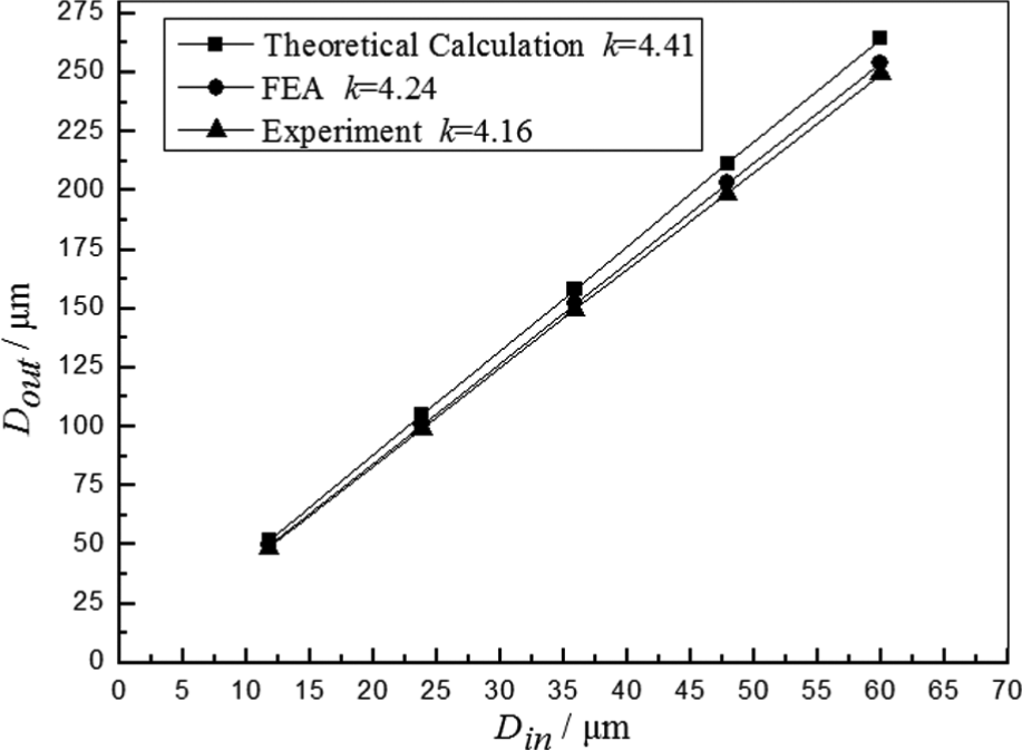
Relationship between input and output displacement by different methods.
The error between the experiment and the FEA simulation is 1.89%, while the error between the experiment and the theoretical calculation is 5.67%. The three displacement amplification ratios by different methods are very close, which has proved the correctness of the theoretical calculation formula (7).
Apparently, the experiment is repeatable. In order to analyze the errors quantitatively, the experiment was repeated three times with the same experiment condition, and the error bars to data series are shown in Figure 7.

Error bars to data series of experiment.
Some reasons that cause the error are as follows:
There is a certain degree of deviation between the actual geometry and the design geometry because of the machining error, which results in the error between the experiment value, FEA simulation value, and the theoretical calculation value, especially when the compliance of the whole micro-gripper mechanism is affected obviously by the minimum cutting thickness t and the notch length h 1.
The theoretical calculation only considers the deformation that occurs in the notch of flexure hinge and regards other part of flexure hinge as a rigid body. Consequently, the deformation of other parts was all ignored, and the internal stress was also ignored at the same time. Actually, there is indeed deformation in other parts of flexure hinge, while the FEA simulation and the experiment include the ignored deformation; that is why the theoretical calculation value is larger than the FEA simulation value and the experiment value.
There is a unavoidable phenomenon of work hardening when the asymmetric micro-gripper mechanism was in the processing of WEDM, and the stiffness of the mechanism increased, which resulted in the decreased deformation; that is why the experiment value is smaller than the FEA simulation value.
Conclusion
Aiming at the requirements of micro-assembly for microtubule (diameter of 0–200 μm), a new type of the asymmetric micro-gripper mechanism, which was driven by piezoelectric actuator, was proposed, and its structure was studied in detail. The output displacement of the right micro-clamp was amplified and transmitted based on flexure hinges, and the flexible parallel four-bar mechanism was used to ensure that the movement of the movable micro-clamp is parallel to the immovable micro-clamp. That is why the microtubule would not be destroyed by the nonuniform force caused from the inconsistent output displacement of both sides of micro-clamps.
The displacement amplification ratio was discussed theoretically based on the lever principle and the output features of parallel four-bar mechanism. The key structure parameters of geometry were pointed out by making use of the FEA method. The result of FEA simulation shows that the displacement amplification ratio is 4.24, and the error between the theoretical calculation result and the FEA simulation result is 3.85%. Therefore, the asymmetric micro-gripper mechanism could perform the micro-assembly task for the microtubule components in the diameter of 0–200 μm only if the piezoelectric ceramic actuator is suitable.
The actual asymmetric micro-gripper mechanism was processed by line cutting of electric spark, and the measurement experiment of the displacement amplification ratio was carried out. The experiment result shows that the displacement amplification ratio is 4.16. The error between the experiment and the FEA simulation is 1.89%, while the error between the experiment and the theoretical calculation is 5.67%. The three displacement amplification ratios by different methods are very close, which has proved the correctness of the theoretical analysis and calculation. The reasons that may cause the error between different methods were also discussed in detail. The asymmetric flexible micro-gripper mechanism is able to perform the micro-assembly tasks for the microtubule parts, and it is helpful to design this type of micro-gripper mechanism.
Footnotes
Academic Editor: Xiaotun Qiu
Declaration of conflicting interests
The author declares that there is no conflict of interests regarding the publication of this paper.
Funding
This research received no specific grant from any funding agency in the public, commercial, or not-for-profit sectors.